Overview
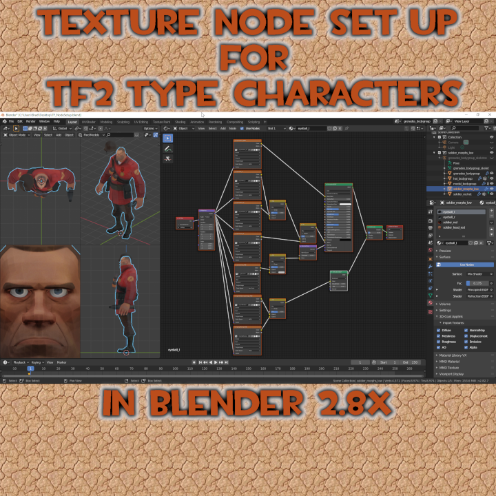
Things have gotten a little more difficult when dealing with texturing models in Blender 2.8xWorking with nodes in the Shader/Node Editor was something I put off while the Blender Render engine available and texture solid was still a useful tool. I was more or less afraid of the node editor, it seemed so complicated and I did not like Cycles. For my purposes, I only needed to see how my textures worked on a model because I work in the Source engine and material settings from Blender don’t mean much in the Source Engine. What I’m showing here is how I get textures to work in 2.8x and it is something I am still learning because I procrastinated on switching to Cycles in the 2.5x to 2.7x days. Therefore, I am by no means an expert on this node thing, and as I just said, I am only beginning to learn how to use nodes and what they actually can do. My Shader node set ups are merely something to get textures onto a model and give me a half decent render out of the Eevee or Cycles render engines if I need one. They also give me a way to produce base color textures if I make changes to them and need to re-bake them from Blender. So if you need something more detailed or a better explanation on what node you should be using or what it does, then you’ll have look somewhere else. Every model will be slightly different and/or use different textures, but the concept here is will apply to most model types.In this guide will show you how I set up my Shader Editor nodes in Blender 2.8x to texture the TF2 Game low poly Soldier (and even get the eyes to look half decent at that.)I use a lot of ping-pong pictures in my guides. Just follow the letters/number and read the text associated with that letter/number. As with all my guides, I try to provide highres and good quality pictures. If you can’t read an image in the guide itself, just click the image to blow it up or right click it and copy the URL and open it in a web browser.
Yes, Blender Render is Gone! Welcome to Cycles and Eevee.
With the release of Blender 2.80 we saw a lot of our old, easy to do things disappear. One of these was the Blender Render engine. With this old engine we could set up base textures on the fly and see what they looked like on the model and even get a half decent render of the model from Blender showing how they might appear. We could quickly flip from solid (clay) mode to a texture solid mode and see the textures on the model simply paint our models.
With Blender 2.80 we lost a lot of this flexibility. In order to set up textures, not only do we have to make sure that the mesh is assigned to UV Maps properly, we have to set up shader nodes in order to paint the model. These can be simple node, but if you really want to see what these textures will look like, we now have to set up more complex nodes and establish proper lighting.
We can no longer just paint the solid model with texture solid, but have to actually change to a textured or rendered mode to see them and if the lighting is not set up properly, our textures aren’t going to look right. (BTW, The shader node illustrated here is just the shader node I use for the eyeball_L material.)

In this guide, I’m going to illustrate the 6 materials needed to set up the soldier’s textures and how I set up my Shader nodes to use the 21 different textures needed by them. (21 because I have stripped the alpha channels out of the images and made individual images for them.)
Materials and Textures (VMTs and VTFs)
The soldier I’m using in this guide is a decompiled copy of the TF2 Game cache VPK player model. This is the regular game player model. I have not added the Flex VTA to it in my images as Flexes are not required for this guide.
If you want to decompile it and use it to follow this guide, extract it from the TF_Misc_dir.vpk file found in the Common/Team fortress 2/tf folder.
The Soldier is made up of 5 mesh objects (also known as bodygroups)

2) The helmet is its own object and known as the hat_bodygroup
3) The Medal is its own object and known as the medal_bodygroup
4) The head and body are combined into one object and is known as the the Soldier_Morph_low or high (depending on the model you’re working with, game player model is low, the HWM is high),
5) The rocket is its own object and known as the soldier_rocket
If we select an object and look at the materials for it in Blender, the name of the material in Blender is the name of the VMT we’re looking for from wherever you’re getting your VMTs from.
The Soldier_Morphs_Low object uses 4 materials, Eyeball_L, Eyeball_R, Soldier_Red and Soldier_Head_Red.
One of these materials (the soldier_red is shared with 2 other Objects, The hat_bodygroup and the grenage_bodygroup objects.
The Medal_bodygroup object and the Soldier_rocket each have their own materials, medal and w_rocket_01
To paint the model in Blender we require the 6 materials (VMTs) files and textures (VTFs) that these VMTs call to make up the model.
The materials (VMTs) are found in the in the materials folder of the TF_misc_dir.vpk and textures (VTFs) are found in the materials folder of the TF_Textures_dir.vpk file.
The reason why we require the VMTs is that they list the all textures that they call. For example the soldier_red VMT calls 4 VTFs,
1) a base texture found in the materials/models/player/soldier folder as the soldier_red.vtf
2) a bump/normal map found in materials/models/player/soldier folder as the soldier_normal.vtf
3) a detail texture found in the materials/effects/tiledfire/ folder as the fireLayeredSlowTiled512.vtf
4) and a light warp texture found in the materials/models/player/pyro/ folder as the pyro_lightwarp.vtf
So as you can see, not only does the VMT tell us what textures are named, it also tells us where the textures are in the materials folders and we require these textures (VTFs) to paint the models.

Once we have the VTFs, we have to convert these to an image format that can be used by Blender. Because some of these VTFs have Alpha channels (used for different types of masks) they should be converted to a format that supports the alpha like PNG or have the alphas split out of them into individual image files (which is what I have done here. I have the RGB channels in one image and the alpha channel of the image in another, this allows me more flexibilty on how I use the masks in the Blender shader definitions.) You can use VTFEdit or GIMP to convert these images.
You may find that there are alpha channels buried in the textures or normal maps and this is an example of the iris texture called by both the eyeball_L and the eyeball_R materials that show the alpha channel and how I split the texture and alpha channel into separate images.


The following image shows the VTF textures that I’ll be using in this guide. These are shown in their respective VPKs. (Yes, you can now extract files from VPKs using Crowbar as long as you have the most recent version.)

Setting Up Materials to Use Nodes
With Blender 2.8x we were given a new functionality, we can select multiple mesh objects and take them all into edit mode together. This is a fantastic feature not only for checking what vertexes are associated with things like vertex groups and materials, it’s a great tool now for unwrapping projects, but more on that in a different guide.
When setting up shaders, you only have to set up one shader for each material, it doesn’t matter how many mesh objects use a material. So, in the case of Soldier_Red, there are 3 objects (the helmet, the grenades and the soldier’s body) that use that one material. I only have to set up a shader node once and all 3 objects will use that shader. It’s the same material.
This image shows some of the Nodes I use when setting up shaders for textures.
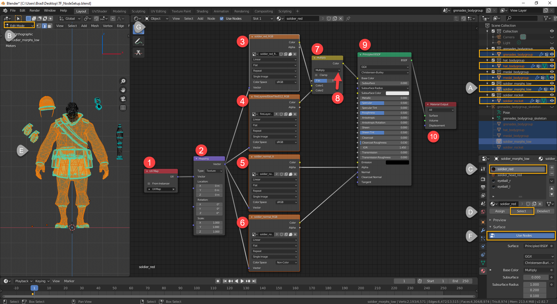
A) I select the objects I want to set up, the last one selected is the object I want to be active. (In this case the soldier_morphs_low is the active object),
B) I put the objects into Edit mode.
C) I select a material
D) then press select.
E) the vertexes selected and glowing are all assigned to that material meaning that the selected area will be coloured when I set up the shader node.
F) I press Use Nodes so it is selected
G) I split my work area and load the shader editor.
When the shader editor opens, the Principled BSDF (9) and the Material Output (10) nodes will already be present.
1) The first node I add is a UVMap Node, this will contain the shader to the UV Islands the vertexes are assigned in the map.
2) I then add a Vector node and set the type to Texture. This node allows me to move, rotate and scale the textures connected all at the same time (if I have to.)
3 – 6) These are image texture nodes and I need one for each texture image I plan to use on the material. There are various setting available and they affect the way an image is applied to the model. All here with exception of the Normal texture are set to their default settings. Normal maps are “non-color” textures and need to be set as such in order for them to work properly.
7) This is a RBG color mixer node. It allows my to blend 2 textures together. The 2 textures I have plug into it are a RGB texture and an Ambient Occlusion type texture.
8) This is a drop down box on the mixer, it allows me to choose the type of blending I want to do with the 2 textures and the fac slider below it allows me to control how much influence one texture has over the other. Because one texture is an AO type texture, I’ve set this to Multiply because I only want the black areas of the texture to come through on top of the color texture.
9) is the principled BSDF (bidirectional scattering distribution function) node. This is where the nodes that make up the the paint job come together. Nodes are plugged into their respective receptacles and sliders set to values that you want and the math elements of the node take over.
10) In order for the textures to display, they need to be pushed out of the shader back to the material. This is where the Material output node comes into play. The node can push out to the Eevee or the Cycles render engine separately or both (all) depending on where you point the drop down box. There are 3 different types of return, Surface for textures, Displacement for displacement maps and Volume (Something I still have to research, but I believe this has to do with volume inside an object, whether light is absorbed, emitted or scattered.)
Because we’re painting an object with textures, the output will be set to Surface.
Once you have the textures displaying on the model, you can start playing with the various values by moving sliders and the textures on the model will react in real time.
Just remember that material setups here will have no bearing on how the textures will display in game. These material settings are for rending out of the Blender render engines only (Eevee and Cycles). In-Game materials have to be set up for the game engine you’re going to use, be it Unity, UnReal or for in our case the Valve Source engine via VMT commands.
The Nodes for the 6 Materials Shaders – (The Explanation)
Because of text limitations, I’ll have to break the sections up by materials but as a kick off let me start here.
Materials the model uses and the mesh objects (bodygroups) that use them:
1) soldier_red – used on the soldier_morphs_(high/low), hat_bodygroup and grenade_bodygroup objects.
2) solder_head_red – used on the soldier_morphs_(high/low) object
3) eyeball_L – used on the soldier_morphs_(high/low) object
4) eyeball_R – used on the soldier_morphs_(high/low) object
5) Medals – used on the medal_bodygroup object
6) w_rocket_01 – used on the soldier_rocket object.
So as we can see from the above, a material can be used on multiple mesh objects and a mesh object can have multiple materials. When setting up shaders, we only need to define the shader for a material once.
Each material can use multiple textures and texture types and we use nodes in the shader editor to tie these textures to the material and pass these nodes into a BSDF shader node to have blender work the math to display them. The primary node for loading pre-made textures into the shader is the Image Texture Node. There are other Texture type nodes, but most of these are procedural/effect type textures (like Brick, Noise, Sky, Environment, Voronio, etc) that are built on the fly and are Blender type textures Blender and require quite a bit of set up to use. I won’t be going into these type of textures because the textures this model uses are all pre-made.
All my shaders start with a UVMap and Vector node. I explained these nodes back in the Setting Up Materials to Use Nodes section.
These feed into a combination of Image texture nodes, RGBMix Nodes, which feed into the various shader input receptacles depending on which shader they are suppose to drive in the Principled or other BSDF Nodes.
BSDF stands for Bidirectional Scattering Distribution Function and I’m not going to define this any further. If you want to know more about what this function is or what it does, you’re going to have to google. (I don’t want to turn this guide into a major tome.)
The Image Texture Node is the main node for loading 2D images as textures. There are various settings in the node that tell the shader what type of textures your using (single image, image sequence and MP4 (for animated textures), Generated (for UV placement) or Tiled (for sprites). whether or not the texture repeats into infinity (like a seamless image), is extended (haven’t used this setting) or is clipped (the image does not repeat or extend beyond its boundaries. Whether or not it is a flat 2d, box, sphere or cylindrical (tube) type image, and how it is to be applied to the UV (Linear, Closest, Cubic or Smart) For most textures I leave these at their default settings. There is one more setting that is important though and that is the Color Space setting. The default setting is sRGB, which means that it will use the color channels in the image. The other setting here I use is Non-Color, this setting is used for Bump/Normal maps.
Sound complicated, but it isn’t really, it’s all a matter of figuring out what texture drives what shader Routing them through mixer nodes so the blend together and plugging them into the right shader input of the BSDF nodes.
So let’s get started with a simple one. The Soldier_Red.
The Soldier_Red Material Shader Setup
This material is made up of 4 textures, the soldier_red, fire_LayeredSlowTiled512 (also known as the Burning Player overlay), soldier_normal_A (which I split out of the soldier_normal texture and discussed earlier) and a normal/bump map called soldier_normal .
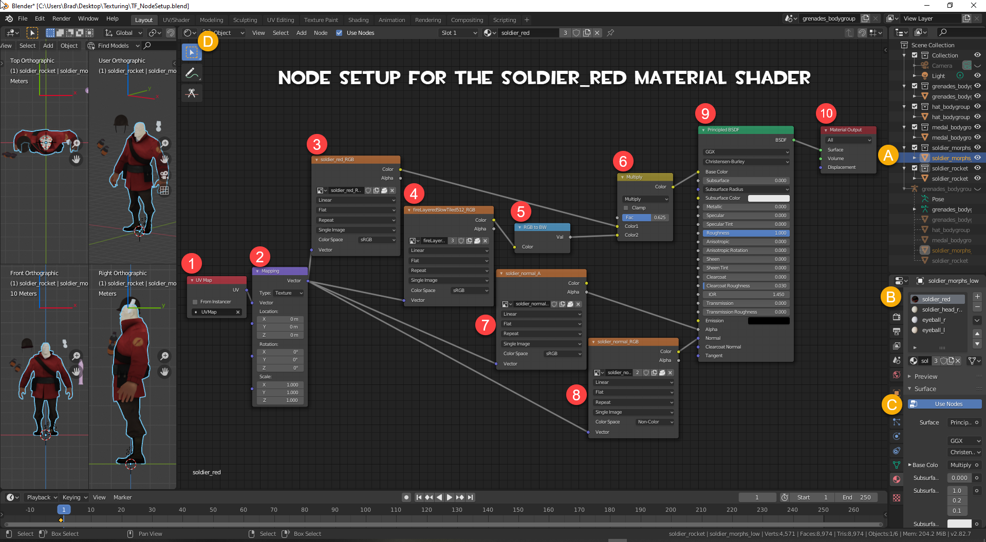
To start the process:
A) Select the mesh object you want to work with
B) Select or create the material you want to work with
C) Click Use Nodes
D) Split your screen to create a work area and Open the Shader Editor
This Material Shader will have 10 Nodes
1) UVMap Node – Discussed earlier
2) Vector Node – Discussed earlier
3) Image Texture Node #1 – this node points to my base (diffuse, albedo, base color, main, whatever you want to call it) texture (in this case the soldier_red_RGB texture), this is the texture that carries the coloring for the mesh. This node can be plugged from the Color output of this node directly into the Base Color input receptacle of the Principled BSDF Node. However, if you have a texture for ambient occlusion that you want to blend into the base texture then you want to add a RBG Mix Node and plug this node into the top Color input receptacle. I want this texture to be my main texture and be next to the mesh.
4) Image Texture Node #2 – This texture (fire_layeredslow_tiled512_RGB) is not required for texturing purposes in Blender if you just want to view what the textures will look like. It is the Detail texture for what I think is the Burning Player material. However, I’m going to use this texture like an Ambient Occlusion type texture to demonstrate how I would append that type of texture using a MixRGB node.
5) RGB to BW (conversion) Node – As AO textures are usually grayscale and this one is colored, I’m going to take an extra step here and run this through a RGB to BW node to strip the color from it. With the color stripped, it will act like an AO type texture when I use the multiply blend mode in the next step.. The Val output receptacle then plugs into the bottom color input of the same MixRGB node I plugged the main texture into, I want this texture to be on top of the main texture.
6) MixRGB Node – Don’t get this node confused with the Mix Shader node, a Mix Shader node is used to combine different BSDF shader nodes together where a MixRGB node is used to blend the RGB channels of 2 textures together.
The drop down box of the node allows us to define the blending method for the image. These are Mix (also known as Normal mode in an image editor), Darken, Multiply (used with AO type textures), Color Burn, Lighten, Screen, Color Dodge, Add, and others.
Mix nodes work from the Top Down, the top color input is the main texture and is the texture that is next to the mesh, the bottom input is the secondary texture you want to append over top of the main texture. But play with this, the other way around may work better for you and this can become very confusing if your using more than one MixRGB node to append many textures over top of others.
The Fac(tor) slide allows the control of the influence the textures have on one another (to the Left for more to the top input and to the right for more influence to the Bottom input), its default is .5 (or 50%) to both textures.
Use this slider to dial in what you want for strength.
After combining the 2 textures through the MixRGB node, I plug the node output into the Base Color Input receptacle of the Principled BSDF Node.
7) Image Texture Node #3 – this is an Alpha (soldier_normal_A) texture node.
If it use for transparency, the Color Output is connect to the Alpha Input receptacle of the Principled BSDF Node.
If it is a mask texture, like a environmental mask, a sheen mask, a mask depicting the amount a metal shines, etc, it is plugged into the input receptacle of the shader it is suppose to control.
This is why I separate Alphas from their main image. I can use RGBMix nodes to combine the alphas together for the various shaders and send a combination to the shader type it needs to control.
Now, I could do the same directly from the original image but the spider webs from the texture would get extremely complicated color output going one way and alpha going another.
By separating alphas out of the images, I can create cleaner node chains and it is easier to change values where needed.
Here I plug the Node Color output into the Principled BSDF Alpha Input receptacle.
8) Image Texture Node #4 – This is a bump/normal map (soldier_normal_RGB) node. If you notice the Color space used on this node it has been change to from sRGB to Non-Color. This means that changes to the material are base on Data from the image rather than its color. Bump/normal maps plug into the Normal Input receptacle of the Principled BSDF Node.
9) Principled BSDF Node – Depending on the complexity of the material you’re trying to make, you can have as many of these nodes in the shader as required with different node chains plugging into them, and we’ll see how these are connected into the final material output using a ShaderMix Node later in the Eyeball example.
This is the main shader control node that the other nodes will plug into for processing. It contains various input receptacles for different types of texture modes. If another node is plugged into a shader input, the nodes input values back to the origin of the node chain will control the data into that input and to make changes to the output of that shader, the values in the chained nodes have to be changed.
If an input receptacle isn’t used, the sliders associated with that input can be used to add or subtract the type of shading to the texture.
As there is only 1 BSDF Node here, I plug the BDSF output directly into the Material Output node.
10) Material Output Node – each material will general only have one of these (depending on the type of material your trying to create.) However, if the material serves a multi-purpose, like is a painter and a displacement type material and control how the Volume of the model reacts, it can have up to 3. One for Surface, one for displacement and one for volume, with different chains flowing into them.
Once the shader is set up and the chain ends at a Material Output node, the model begins to take on color.
If updates to the values in the nodes are made, the texture will change in real time.
If you now look at the 3 objects that use the soldier_red material, you should find them painted with textures.
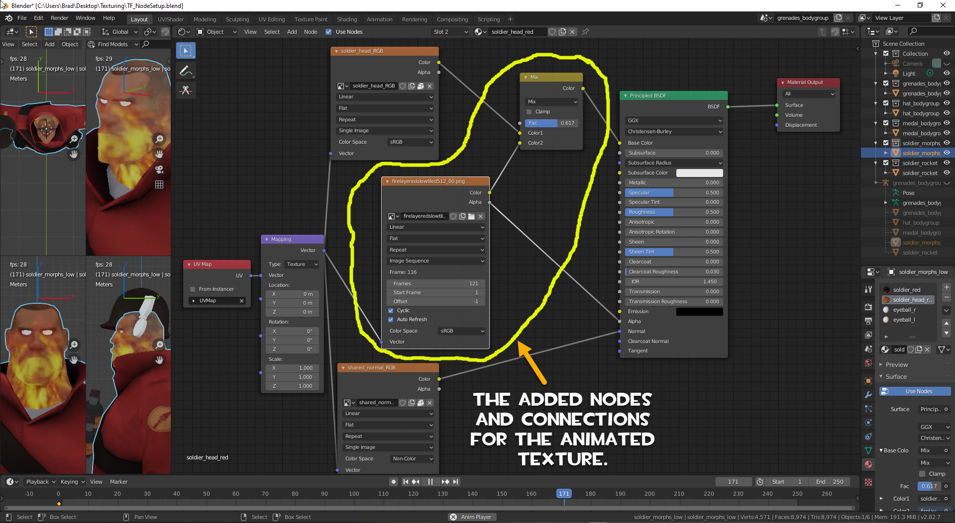
The Soldier_Head_Red Material Shader Setup (with Flair)
The head object is probably the simplest to set up. There are only really only 2 textures required to set this up to view what they look like in Blender. The soldier_head_red and the shared_normal bump/normal map. But we’re going to take this one step further and set up the fireLayeredslow512 texture as a detail texture in Blender and display it the way it would look in game.
The FireLayeredSlow512.vtf is an animated VTF and to use it in Blender as an image sequence texture we have to extract all the images from the VTF to an image format that we can use in Blender. I’m going to export these images as .PNG files
To do this I’m going to open the texture in VTFEdit.
Although this VTF is only 64×64 pixels in size, the animation sequence contains 121 images. To export these images as individual PNG files, select File, Export All. (Selecting export only will only extract the current frame the animations is stopped at.) Point the file browser to an empty folder or create on on your desktop, change the .TGA default file type to .PNG and press OK and VTF Edit will happily spit out all 121 frames of the animated texture as PNG files.
However there is a problem, the naming conventions of the export files does not match the image sequence naming conventions that Blender needs to identify the images as a sequence. VTFEdit spits out images with names like firelayeredslowtiled512_00_00_00.png, firelayeredslowtiled512_01_00_00.png, firelayeredslowtiled512_02_00_00.png to firelayeredslowtiled512_120_00_00.png. Blender requires names to be in the format of firelayeredslowtiled512_00.png to firelayeredslowtiled512_120.png for it to identify them as image sequences, the back part (the _00_00) in the file names have to go and the only ways to do that is with a program that changes filenames or manually, one by one.


There just happens to be a free renaming program out there that was written between 1999 and 2005 by Ivan Anton that, yes, still works in Windows10. The name of the program is Lupas_Rename 2000 and the last version produced was V5.0. It can still be downloaded (at the time of this writing) here. [link] Grab the portable version in the ZIP format, extract it anywhere on your computer and run it from there. No install required. Rename the exported image files like this.
Remember where you put these files for later.
Now we can set up the Shader Nodes.
First I’ll display the Shader Node set up for just display the normal textures. After the explanation, I’ll display the set up for appending the Burning Player detail texture to the shader node as a bonus feature.
Same startup process
A) Select the Object you want to work with
B) Select the Material you want to set up
C) Select Use Nodes
D) split the screen to give yourself a workspace and open the Shader Editor
Looking at the VMT, we see that there are only 2 textures needed for the head. The soldier_head texture and the shared_normal bump/normal map. There are no Alpha masks or any transparency in this texture. So to set this simple shader up:
1) Add a UV Map Node
2) Add a Vector Mapping Node
3) Image Texture Node #1 – Add an Image Texture node and point the node at the soldier_head texture.
4) Leave the Default drop downs alone ensuring that the Color Space is set to sRGB (this is our Base texture.)
5) Plug the color output from Node #1 into the Base Color input of the Principled BSDF Node
6) Image Texture Node #2 – Add another Image Texture node and point it at the shared_Normal texture. Leave the drop downs at default
7) BUT change the Color space drop down to Non-Color (This is a Bump/normal map and the shader has to read data, not color from this texture)
8) Plug the color output from Node #2 into the Normal Input of the Principled BSDF Node.
9) If the Material Output node isn’t already in the shader and the BSDF output connected connected to Surface Input receptacle, Add one and Make It So! The head should color as soon as the Material Output is connected to the Chain.
10) make adjustments to the various values until your happy with the out come.
Done.
Now a for little magic.
1) Add another Image Texture Node between Image node #1 and Image node# 2.
2) Click the Open Folder button on the new node to open the file browser and point the browser to the folder that the images for the fireLayeredSlow512 image sequence are in. (Look back, I told your to remember where you put them.)
3) Select the first file and press A to select them all and click Open Image.
If you named the files properly, the Image Node should automatically change to Image sequence, it will count the number of frames in the sequence, set the start frame to 1 and Offset should set to -1.
4) We want this image sequence to player continuously, so click the Cyclic box so there is a check mark there, and
5) click the Auto Refresh box so there is a check mark there.
Color Space should be set to sRGB
6) Connect the Vector output from the vector mapping node to the Vector Input of the image sequence texture node.
7) Now add a MixRGB node and leave it at default for now.
8) Connect the color output from the base texture node into the top color1 input receptacle of the MixRGB node
9) then connect the Color output from the Image Sequence node into the Bottom Color2 input of the MixRGB node.
10) Connect the color output of the MixRGB node to the Base Color of the Principled BSDF node.
11) In case there is alpha in the fire texture, connect the alpha output from the firelayeredslow512 Image Node to the Alpha input of the Principled BSDF node.
12) Set the Fac value in the MixRGB node to somewhere around .25 to start and
13) press the play button on the time line.
Congrats, you just set up your first animated texture in Blender and your shader set up should look something like this.

If you want more flame pull the Fac slider to the right to give the secondary texture more influence and play with the various blend modes of the MixRGB shader (I think Mix and Add are the best for this).
The Eyeball_L/R Material Shader Setup
Now we get into a fairly complex shader, the eyeball shader. There is no way that we will ever get QC eyes into Blender but we can get kind of close to them. One of the saving graces of this shader is that once we get one set up and working, we can just copy and paste the node set up into the other material shader and it “should” work.
QC eyes use a series of textures that are controlled with a flex slider that float over the eye mesh when the controller is moved. There are no bones and there is no moving mesh in a qc eye. On top of this most times the eye is a convex shaped chunk of mesh that has vertex welded to the actual head. The eyes are not rounded orbs.

The Valve “EyeRefract” shader uses the following textures:
The eye-iris-blue (brown or green) This is the primary and base color texture for the eye and is located in the RedBlueGreen channels of the texture. This texture also has the eye cornea noise embedded in the textures alpha channel. If you remember I’ve split the Alpha apart from the RGB channels into separate textures
.
The eye-extra texture is the eye’s ambient occlusion the Alpha channel is not used on this texture
The eye-reflection-cubemap- texture is a reflection texture and is used by the environment cube map in game. We’re going to use a special BSDF shader for this one.
The eye-cornea texture is that contains a 2D cornea normal in Red/Green channel but also contains other data in Blue and Alpha channel (this is a texture that I’m still trying to figure out)
The eye_lightwarp” is a light warp texture which enables TF’s Non Photo Realistic lighting in Game and I don’t think we need this one in Blender.
One of the challenges is to be able to make all these texture float on the eye mesh, together.
This is an image of my shader node setup.
Looking at the looking at the shader itself, you’ll notice that I have 2 map vector nodes and the chains are split off both of them. I’ll explain why in a minute.
Also, if you study the textures used and look at some of the chains, you might get an idea of why I study the VMTs and spit things into separate textures. If you bake textures from Blender, they will be blended back together based on how you set the baking.
So, lets get into the setup. Because this is a more complex set up, I’ll start with the left side of the chain for the eyeball_R material first. This will get the base texture of the eye and Normal textures displaying, then we will work the right side chain to clean up the alpha and set up the refraction.
This is the Left chain set up and now that you’re starting to get the hang of this, my explanations are going to be shorter.
Select the Eye material you want to work with and make sure Use Nodes is turned on.
1) UV Map Node (plugs into the top Vector input of the Vector Mapping node)
2) Vector Mapping Node (plugs into the Vector Inputs of the 4 Image Texture Nodes)
3) Image Texture Node – Base Texture – Uses the RGB of the Iris texture (plugs into 5 (RGBMix Node Color1))
4) Image texture Node – Uses the RBG of the Eye Extra texture ((this will be an AO texture and plugs into 5 (RGBMix Node Color2))
5) MixRGB Node – set to Multiply to blend the AO into the base texture (Plugs into 6 the Base Color Input of the Principled BSDF Node)
6) Princpled BSDF Node – Base Color Input
7) Image Texture Node – Cornea Bump – Set Color space to Non-Color – Uses the RG image of the Cornea texture (plugs into 9 (RGBMix Node Color1))
8) Image texture Node – Addition Cornea Bump information – Set Color space to Non-Color Uses the BA of the Cornea texture (plugs into 9 (RGBMix Node Color2)) This will also plug into another MixRGB node in the Right Side Chain!!
9) MixRGB Node – set to Mix (Plugs into 10 the Color input of a Normal Map Node)
10) Normal Map Node – Set to Tangent Space – (Plugs into the Normal Input of 11 the Principled BSDF Node)
11) Princpled BSDF Node – Normal Input
If the BSDF output of the Principled BSDF node is plugged into the Material Output node, the eye you’re working on should color.
If this is all you want your model to do, then you’re done with this eye and you can skip over the setup of the ride side Chain and carry on to the set up of the other eye below it.
If you want the Alpha to get the eyeball effect and refract, then let’s walk through the Right side chain now.

2) This is a Second Vector Mapping node. It will control the vector setting for the Right Side Chain. It plugs into the 4 Image Texture Nodes.
3) Image texture Node – uses the Eye Extra Alpha texture (plugs into 5 Mix RGBMix Node Color1)
4) Image texture Node – uses the Cornea Alpha Texture (plugs into 5 Mix RGBMix Node Color2)
5) MixRGB Node – The VMT states there is extra info in the Cornea B/A texture. I plug the color output from the Image Texture Node (#8) on the left side into the Fac(tor) node here as well. Blends the alpha textures together – Set to Mix (Plugs into 6 The Alpha input of the Principled BSDF Node)
6) The Principled BSDF Node Alpha Input
7) Image texture Node – uses the Eye Reflection CubeMap texture (plugs into 8 Mix RGBMix Node Color1)
8) Image texture Node – OPTIONAL – uses the Eye Lightwarp RGB Texture – this may or may not make any difference on the eyeball display, It’s something you have to try out. (plugs into 8 Mix RGBMix Node Color2)
9) MixRGB Node – Blends the Reflection and lightwarp textures together – Set to Mix (Plugs into 10 the Color input of a Refraction BSDF Node (a new shader))
10) Refraction BSDF Shader Node – This node is the node that will add reflection of light to the eyeball. It is a separate BSDF shader and because there is only one input to the Material Output node we can’t plug both the Principled BSDF and this one into it. So now we have to had a MixShader node so we can Blend the two BSDF shader together. This will plug into The bottom shader input because we want it to ride on top of the stuff coming from the Principled BSDF shader.
11) MixShader Node – Joins the Principled BSDF and the Refraction shaders together into a single output. Works the same as the MixRGB node, move the Fac(tor) slider to the left of the 50% mark and Shader 1 has more influence, to the right and Shader 2 has mor influence.
12) Material Output Node – Sends the shader output designed for the render engine selected (Eevee, Cycles or All), for the material type selected (Surface for textures, Displacement for Displacement maps, or Volume.)
Now that all the textures have been assigned and all the connections connected, the eye should show up on the model. Now it a matter of playing with the settings in the nodes to get it to display the way you want it to.
Done (with one Eye)

1) press A in the shader editor so all the nodes are selected,
2) press Ctrl+C to copy them to your clipboard (Not SHIFT D to DUPLICATE them),
3) select the other eye material and make sure Use Nodes is turned on
4) select the nodes that are in the shader already and press X to delete them,
5) press Ctrl+V to paste the nodes from the other eye into the shader.
6) Done! The other eye should now texture and both eyes materials are using the same shading set up in their materials.

The Medals and w_Rocket_01 Material Shader Setup
We’ve done a couple of easy textures now and by now you should be saying, “This is pretty simple”! You should have a pretty good Idea on how the finish the model, but for those that still aren’t quite getting it, I’ll try to finish off the Medal and the Rocket in this section.
Select the Medals Mesh Object, then Select the Medals material, ensure Use Nodes is turned on. Split the workspace and open the Shader Editor.

1) UVMap Node (plugs into the top Vector input of the Vector Mapping Node)
2) Vector Mapping Node (plugs into the Vector Input of all Image Texture Nodes)
3) Image Texture Node 1 – Base Color texture (medals_RGB) – Plugs into the Color1 Input node of a MixRGB node (4))
5) Image Sequence Texture Node 1 – an animated texture (FireLayeredSlow512_00-120) – Plugs into the Color2 Input node of a MixRGB node (6)) We want this yexture on top of the base color when we use it. – Plugs into the Base Color input of the Principled BSDF Node (7)
8) Image Texture Node 2 – Medals Alpha Channel texture (medals_A) – Plugs into the Alpha Input node of a Principled BSDF Node (9)
10) Image Texture Node 3 – Medals Normal/bumpmap texture (flat_normal_RGB) – Plugs into the Normal Input node of a Principled BSDF Node (11)
12) Final connection, the BSDF Output of the Principled BSDF shader connects into the Surface Input of the Material Output Node. The mesh for the Medal should color.
Use VTFEdit to extract the image sequence from the animatedsheen0.VTF to a folder as PNG files
A) Select the w_rocket01 Mesh Object,
B) Select the material,
C) Ensure Use Nodes is turned on
D) Split the screen and open the Shader Editor
1) UVMap Node
2) Vector Mapping Node
3) Image Texture Node – Base Texture (w_rocket01_RGB) – Plugs into a MixRGB Color1 Node(4)
5) Image Sequence Node – Animated Sheen Texture – plugs into a MixRGB Colour2 Node(6) We want this texture on top of the Base Texture.
7) The MixRGB Node plugs into the Base Color Input of the Principled BSDF Node
8) Image Texture Node – This is the Sheen cubemap Texture – plugs into the Sheen input of the Principled BSDF Node.(9)
10) Image Texture Node – This is the Alpha texture and plugs into the Alpha Input of the Principled BSDF Node (11).
12) Image Texture Node – This is the Bump/Normal Map Texture – Plugs into the Normal input of the Principled BSDF Node. (13)
14) Image Texture Node – This is the Weapon Lightwarp texture (used for reflection/refraction) – Plugs into a New Refraction BSDF Node.(15)
16) The Principled BSDF Shader and the Refraction Shader Nodes plug into a Mix Shader Node
17) The Mix Shader Node plugs into the Material Output Node.
Set the 3d Viewer mode to Material or Render Miew Mode and the whole model should now be textured.
Play with the various sliders and values to get the result you want.
This process is how we now add textures to the models we load in Blender. Each model will be different, but this is the way you plug in the textures. As you become more familiar with the process it will get faster.
Why the Vector Mapping Nodes in the Shaders? (Bonus Stuff!)
I said earlier that we will never have QC eyes in Blender. Well, by adding vector nodes and digging into Blender a little bit, we can get pretty darn close.
Viola, QC Eyes mimicked in Blender.
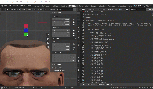
When I got to the eye shaders portion of this guide and added the vector mapping nodes, I had no idea on how to achieve tying the eye textures together like this in Blender, but after maybe 45 minutes of Googling, watching a couple of videos on Drivers and 20 minutes of setup I was able to create this effect.
So, How did I achieve this effect?
This is advanced stuff, so I’m not going to go into detail on this, but will provide pictures and a brief explanation of how I did it here.
The process requires setting up various things, like a three cubes, 6 drivers and constraints on the cubes.
All I do here is create 3 individual cubes objects, one will control the left/right movement (X Location), one will control the up/down movement (Y Location) and one will control the (X and Y) scale of the vectors used by the shaders.
I rename then so I can quickly distinguish which one is which and what element they control. For example,
mvLX (this is the cube I’ll use to move the eye vectors left/right on the X axis)
mvLY (this is the cube I’ll use to move the eye vectors up/down on the Y axis)
mvS (this is the cube I’ll use to scale the vectors)
The Transforms for the model should have already been applied so all the objects that make it up will have a location of 0,0,0, a rotation of 0,0,0 and a scale of 1,1,1 on the X, Y and Z axis.
The 3 cube objects I create can be placed anywhere in the scene (I’ve chosen just over the head here so I can watch the eyes more closely as I move the cubes).
Once in place, Apply the Location Rotation and Scale transforms so the origin points are in the same place as the origin point for the model.
By applying the transforms to the cubes, this sets the Location, Rotation and Scale to the same values as the original model and which makes programming the drivers for the shaders a lot easier.
Now select the object that contains the materials for the eye textures, select one of the eyeball materials and open the Shader Editor.
If you followed the setup I provided for this shader you would have created 2 Vector Mapping nodes, one for left side chain and one for right side chain. The one controlling the Base Texture and Cornea normal/bumpmap is the one that needs drivers add to the X and Y location and scale vectors.
The reason we don’t need drivers on the Z axis is that textures are 2D elements and only move on 2 axis, left/right on the X axis and up/down on the Y axis.
So, here’s the set up
- Select the object that contains the materials for the eyeballs
- Select one of the Eyeball materials and
- Split the screen and Open the Shader Editor and Driver Editors
- Select the Drivers tab in the Driver Editor
The left column of the Driver Editor in my picture shows established drivers, your’s will be empty until you start adding drivers. - Find the Vector Mapping node for the Base Color/Cornea textures,
- Right Click on the X Location Value and select Add Driver, repeat this step for the Y Location, the X Scale and Y Scale values. When the driver is assigned, the color of the value in the Vector Mapping node will change (the default is a purplish color.) This indicates that the value is provided by a driver.
- As you add drivers, they will start to appear in the Left column of the Driver Editor. As they appear, select the new driver and ensure the Driver type is set to Scripted Expression.
Now we set up the Drivers to work so that as we move a cube left or right in the scene, the X transform value is passed to the Vector value it controls. This will move the UV vectors in the direction needed on the texture and make it look like the eyes are moving on the model.
When we click on the Drivers tab in the Driver Editor we find the area where we define the driver, this includes things like Type (and there are a few and the options change depending on the type selected), the controlling object, what’s being passed, and the name of the variable being used to hold the value.
- The driver type (Scripted Expression is the one we’ll work with.)
- What we want to name the variable and the ability to add more if required (note, the name var here is a default place holder and should not be used, this is why we get the Python error in the window.)
- In a script expression driver, this is the block we assign the the controlling object and define what value is being pulled from it. We also define what value is to be used (World, Transform or Local) this is a tricky thing to decide what to use and you’ll have to test them to see what gives the best return for your intended purpose.
- Because we’re using a scripted expression type driver, we’ll have to use some python coding here. (Don’t worry, it’s simple and I’ll give to the code I use and explain it.)
Things are going to get a little complicated now and I’m running out of space here for text, so I’m going to start a new section and carry on.
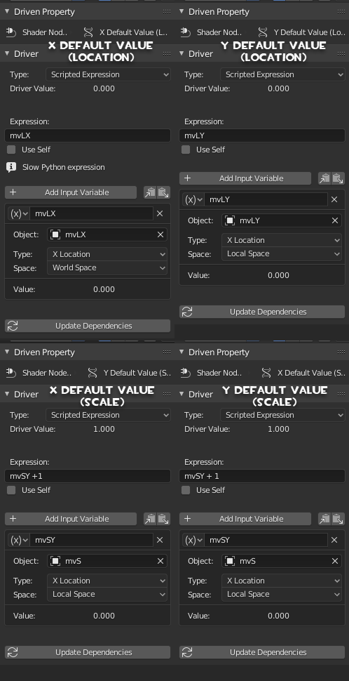
Driver Setup
In this image, I’ve created the vector drivers for both the Eyeball_L and the Eyeball_R materials. You can see this in the Driver Editor on the left in the Node Trees (5 and 6). I’m currently showing the Default driver definition (7) that is created for the Eyeball_R (4) X Default Value (Location) (5), If I were to select each of the drivers in the Node Trees, I would find that the Driver definitions would all be the same.
Type: Scripted Expression,
Expression: var,
Variable Named: var,
No object selected,
Type: X Location and the
Space: WorldSpace

I have my Cubes created and sitting in place and I HAVE APPLIED THE TRANSFORMS to them, meaning the if I select any object in the scene, the Locations and the Rotations would be 0,0,0 and the Scales would be 1,1,1 (Hint, this is important and why I keep harping on it)
Cube 1 is named mvLX and I want the X Location value of that cube to populate the X Default (Location) value of the Vector map node of Both eyes.
Cube 2 is named mvLY and I want the X Location value of that cube to populate the Y Default (Location) value of the Vector map node of Both eyes.
Cube 3 is named mvS and I want the X Location of that cube to populate BOTH the X AND the Y (Scale) values of the Vector map Node of Both eyes.
If I move any of the Cubes right now, nothing will happen, I haven’t set the driver definitions up yet.
This is the definition for the Left/Right (X Default (Location)) driver. Because I want the one cube to drive both eyes, the exact same definition is used for that driver in both eyeball_L and eyeball_R materials.

- Type of driver is Scripted Expression
- This is the name of the variable that will hold the returned value of the driving object. Like x=1, y=3, x+y=4. The variable name can be whatever you want it be (but use the KISS method and Keep It Stupidly Simple). I rename the variable name to the same name as the Object I’m going to use to control (mvLX), but I could have named it x.
- Click the box and chose the object that is going to be the Driver Object. You can also use the Eyedropper to select an object. The mesh object I’m using for this driver is the cube named mvLX.
- Use the Drop down and choose what is going to be returned as a value. In this case, I am only moving the driver object on the X axis and I want the X Location value returned.
This may be different on other models and is dependent on how the UV islands are placed on the UV Map. For example, what might be left/right on the model might actually be up/down on the UVMap because the UV Islands are rotated 90 degrees. So don’t be surprised if the textures move differently than expected when you move the object. Just change the the return object.
- This is a value you have to play with. Options are World Space, Transform Space and Local Space. Because I don’t plan on moving the model, I’m using Local Space.
- The expression. This is a python expression and it can be a complicated as you want to make it.
Because we assigned the transforms for the Cubes so that the origin points the Rotations and the Scales are exactly the same as the model, we don’t have to worry about any type of offsets. Therefore, all we have to calculate into the expression is the value the cube moves on the x axis. This value already exists in the variable. So all we need is that holding variable as an expression and that is the name of the variable mvLX. Variable names in python are case sensitive, so the capitalization, spacing, underscoring, etc has to be exactly the same as the name of the variable or the Driver will not work. If you didn’t apply the transforms for your driving objects or the origin points of the model and the driving object are different, then this express has to take in the account for the Offsets between the origin point of the model and the driver. (And that’s as deep as I’m going to go on that. I’m not here to give a python class.)
This is how this works. I haven’t set up the driver for the Right Eye yet, so only the Left is going to move when I move the correct cube. (Yup, more ping-pong)
- We assign the object that is going to drive the change
- move it (in object mode) on the axis expecting change.
- The location value changes and if the change on the expected axis,
- the value is stored into the variable
- the variable is passed to the expression
- the expression is calculated (all we need is the variable in the expression because all the transforms are the same and we don’t have to worry about offsets).
- The result of the expression becomes the Driver Value
- and assigned to the driver
- The Driver sends the Value to and changes the Vector Mapping value it is controlling
- and the texture appears to move.
These are the current Driver Definition Setups for my Eye Drivers. There are 4 drivers in each eyeball material. The definition settings are exactly the same for the drivers in both eyeballs.
If you look at the Scale definitions on the bottom, you’ll see in the expression an example of adjusting for offsets that I was talking about. The Cubes location is 0 on the X Axis, but the Default Scale is 1 for the model. If I pass the X Location bare, the value is 0 which would set the Scale vector to 0 and make the texture disappear. I have to add 1 to the expression to make the value equal the proper scale of 1.
After all the Drivers are all defined, I add a Limit Location constrain to the cubes. Because I’m only moving these on the X Axis, I only have to set the limit on that axis. I set the limit to the point that the textures begin to repeat themselves in space.
The last thing I do is lock down the transforms on the axis that I don’t want the cube to travel on. (the Y and Z). This way when I move the Cubes, they only move on the X Axis.
Now I can see where the eyes should be at rest and how the eyes should react when I use the Eye Flexes in SFM.

But this isn’t the only use I have for this set up. I can use it as a tool when modeling.
When I’m setting up QC Eyes on a model and on compile I find that the eyes are derping out, it’s usually because I haven’t set the eyeball coordinates properly in my QC. I can recreate the derp in the textures on the model in Blender then look at the value of the 3 cubes and determine where I’ve made the mistake and make a correction in the coords based on those values. If the derp is in the X/Y cube values, I have to adjust the X and Z values in the QC.
If I have to adjust the scale cube to recreate the derp (cause of the Derp in the picture above), that usually means the Y Coords are out. I just add or subtract the x value of the Cubes to the proper coordinates and recompile.