Overview
In this guide we are gonna put together and run the modular engine.This is my first guide and i hope it is easy for new people to understand.If you spotted an error in the guide then please notify me about it.
Building
- First we start with the crankshaft. You can have as many as you want but we are gonna stick to two for simplicity.
- Add Cylinders. Again we are sticking to two, but one crankshaft can hold upto 4 cylinders. When two or more cylinders are together, they will share resources (fuel, air, exhaust, etc)
- Add the engine drive belt to either of the ends. This will be used to drive the stuff in the next step
- Add the following items. Make sure the belt on the items align with the engine belt drive. The coolant manifold has to be attached to the cylinder and not the crankshaft.
Quick info about the fluid pump - Now its time for the cooling. Add a radiator. Red indicates hot and blue indicates cold. Arrows indicates which way the fluid goes. Doesnt matter which port on the radiator or the coolant manifold you use for fluid in/out.
- To attach the engine to whatever were gonna drive, we require a clutch attached to the crankshaft. The clutch allows transfer of mechanical power. It is used to allow the engine to idle at a standstill by disengaging it from the wheels, props, etc. Value of zero is fully disengaged and a value of 1 is fully engaged.
- To expel exhaust, we need an exhaust manifold attached to the cylinder(s) to convert it into a typical pipe port. Were just gonna attach an exhaust port right on it.
- Add a temperature sensor. This will allow you to monitor engine temperature. It must be attached to the crankshaft.
- Now add air and fuel manifold connected to the cylinder. Optionally they can be connected to the cylinders via manifolds (not to be confused with the exhaust manifolds). The manifold can also be used to share resources between cylinders.
- Now add a fuel tank and a fluid port for the manifolds
- Congratz, You’ve put together a modular engine. The process for the 3×3 and 5×5 modular engines is pretty much the same.


Logic wiring
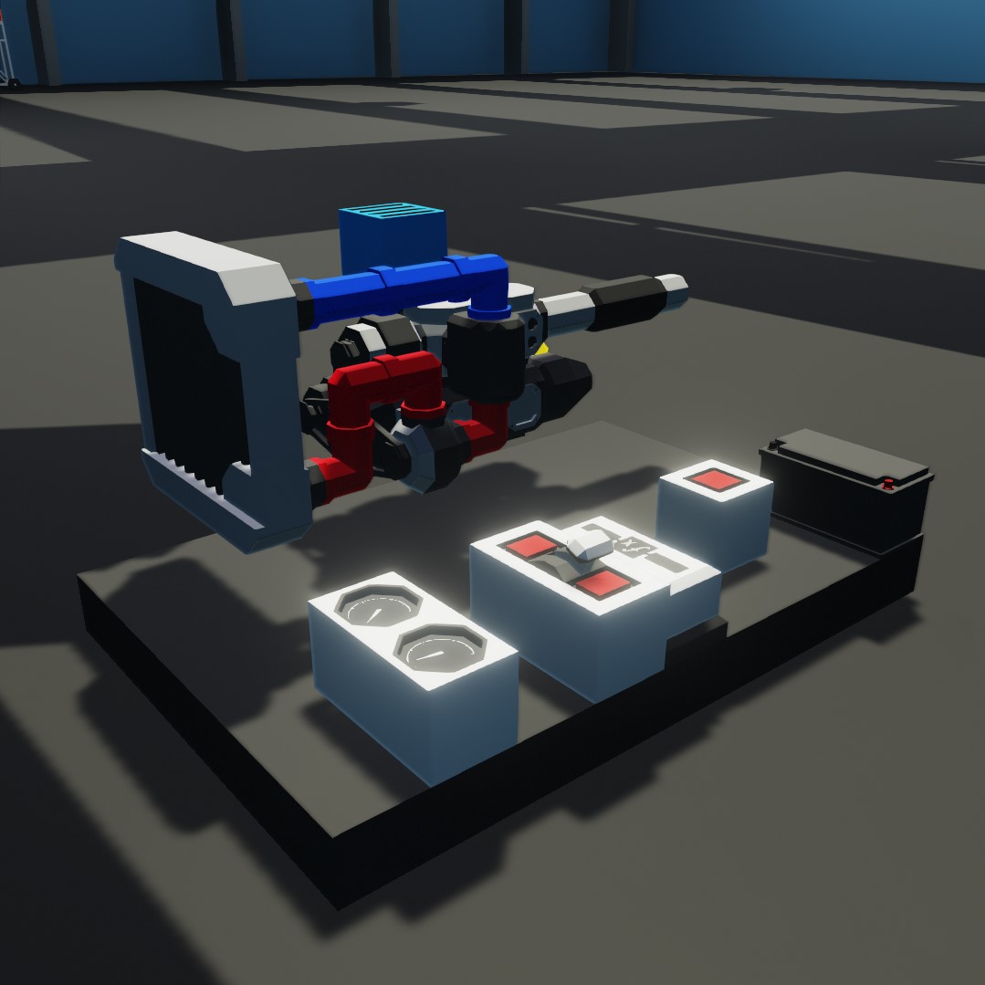
- First lets get the essentials. Add two dials for engine RPS and temperature, throttle lever, function block (well go into that in a bit), push button and a battery.
- Now lets wire everything up to the battery
- Alternator and fluid pump got a clutch. The clutch allows to engage or disengage mechanical force. So with a value of zero the alternator and pump wont do anything and with a value of 1 they will be driven and start producing electricity and pumping fluid. For simplicity were just gonna wire it to the engine RPS
- Now wire up engine temp and RPS to the dials
- Now wire up the button to the starter
- Now the important part. Connect the throttle lever to the air manifold and function block and then connect the function block to the fuel manifold. In the function block type x/2.


PID throttle
Benefit with this setup compared to throttle lever only is you dont need to manage the throttle to make the engine idle and we get an RPS limiter so the engine doesnt blow up.
- Were gonna make this system with the MC editor for a clean and easy view of the setup. First go to the top right in the workbench and select Microcontroller editor
- Now we need to give it a name and size. Make it 3 blocks wide and 2 blocks tall. Lets name it ECU controller.
- Now click the Logic tab. Click the Add Node to add a node. we need the following nodes. Once you got all the nodes, move them on the MC block to not have them overlap one or another
- Throttle input (input from the throttle lever)
- RPS input (RPS from the engine)
- Toggle input ON/OFF (to toggle the PID)
- Air throttle (output to the air manifold)
- Fuel throttle (output to the fuel manifold)
- Starter (output to the starter. Were gonna also make the starter automatic)
- Now go to the top bar and select LOGIC tab
- Now just move the nodes around so they dont overlap eachother. Use the scroll wheel to zoom in/out and to move around hold Alt and drag with left mouse button or hold down middle mouse button (scroll wheel).
Throttle system - On the bottom right of the window click LOGIC GATES or press Tab to open the logic inventory, you can also drag logic gates to the hotbar for easy access.
The logic gates we need for the throttle system is the following:- PID
- f(x) (function)
- Clamp
- Now wire it up as so. For the function block, just click on it then type x/2 and for the PID lets start with the following values. 0.4, 0, 0. Leave the clamp at its default values (min 0 and max 1)


- For the starter we need the following logic gates:
- Less than
- Constant number
- AND
Wire it up like so and set the constant number to 2

- Now just save it, give the save a name then exit the MC editor
Placing and wiring- Remove the push button and function block from the old throttle system and place a key (or a toggle button. Your choice) and the controller we just made. Just go to your inventory and search up the MC’s name (you did name it right?). Remember to rewire everything to the battery again.
- Now wire everything up to the MC (this is where i hope you named all the nodes on the MC), but before we can test it out we need to do some changed to the throttle lever. Click on the throttle lever with the SELECT tool then set min value to 3 and the max value to 20. Start value can be ignored but this is where you put in a value between min and max and it will start at that value when spawned.
- Now you should be left with a functioning engine with a PID throttle.
- Remove the push button and function block from the old throttle system and place a key (or a toggle button. Your choice) and the controller we just made. Just go to your inventory and search up the MC’s name (you did name it right?). Remember to rewire everything to the battery again.


Air to fuel ratio and Stoichiometric
The AFR is the mixture between air and fuel. The best AFR is between 13.6 and 14.5.
- Higher AFR means the engine is running leaner (weak power and more heat)
- Lower AFR means the engine is running richer (slightly more power and more heat)
Now i dont know much about Stoichiometric unfortunately, but from what ive heard you want it close to zero for best efficiency
How to tune the PID
The PID is like so:
P= “How far am i from the setpoint?”
I= “How long have i been away from the setpoint?”
D= “How fast am i approaching the setpoint?”
Normally the “how long” (I) part doesnt matter, but there are some applications where its useful
The idea is like so:
- Increase P until the system oscillates steadily as a reaction to disturbance.
- Increase D until the system only undergoes 1 or 2 oscillations before stabilizing.
- If the system has a hard time reaching the setpoint even if stable, add small amount of I gain. Be aware that if it doesnt reach the setpoint for a while, it will start to act up once the setpoint is lowered with I.