
Overview
A more advanced guide on SR (Set-Reset) Latches and potential applications.
Definition
latch (n) ELECTRONICS; a circuit that retains whatever output state results from a momentary input signal until reset by another signal.
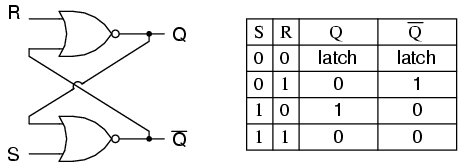
SR Latch Prototype
The SR Latch Prototype consists of
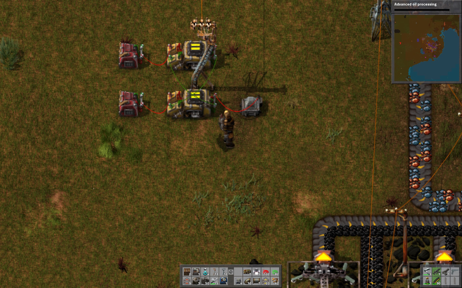
- 2 Constant Combinators
- 2 Decision Combinators
- 1 Lamp
- 5 Circuit Wire (Red or Green)
NOTE: The output color does not affect the end results. This is not necessarily the case in more complex circuit networks but that complexity is not covered in this Guide.

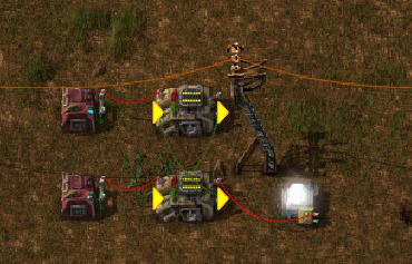
This is the same SR Latch setup but using all Red Circuit Wire.
- Place all combinators and lamps
- Wire Constant Combinators (CC) to Decision Combinators (DC) 1:1. i.e., CC1 connects to DC1, CC2 connects to DC2. NOTE: Be sure that you link the CC to DC input.
- Wire DC1 output to DC2 input and DC2 output to DC1 input
- Wire DC2 output to lamp
- Set DC1 condition to A=0, output A=1
- Set DC2 condition to A=0, output A=1
- Set Lamp condition to A>0
Set condition
When CC1 is set to A=1 (Set condition) DC1 will output nothing. Since CC2 is empty and DC2 outputs A=1 when it receives no value, DC2 outputs A=1 and the lamp (A>0) will turn on.
Additionally, the output of DC2 is applied against DC1, but since the input (A=1) does not meet the DC1 condition, it does not affect the DC1 output behavior.
Reset condition
When CC2 is set to A=1 (Reset condition) then DC2 will output nothing (because the CC2 value output to DC2 is A=1, and DC2 only ouputs A=1 when A=0). This turns the lamp off.

Additionally, the output of DC2 of nothing is applied against DC1. Since this triggers DC1 to output A=1, it is fed back to DC2. At this time, The CC2 input A=1 and the DC2 output A=2 are combined to equal A=2. Since DC2 only outputs A=1 when DC2 receives input of A=0, the lamp remains on.
For further cycles, the output of DC2 of nothing continues to be applied against DC1. DC1 continues to output A=1. Combination of DC1 and CC2 input remains A=2 (stable, but no change to lamp behavior.)
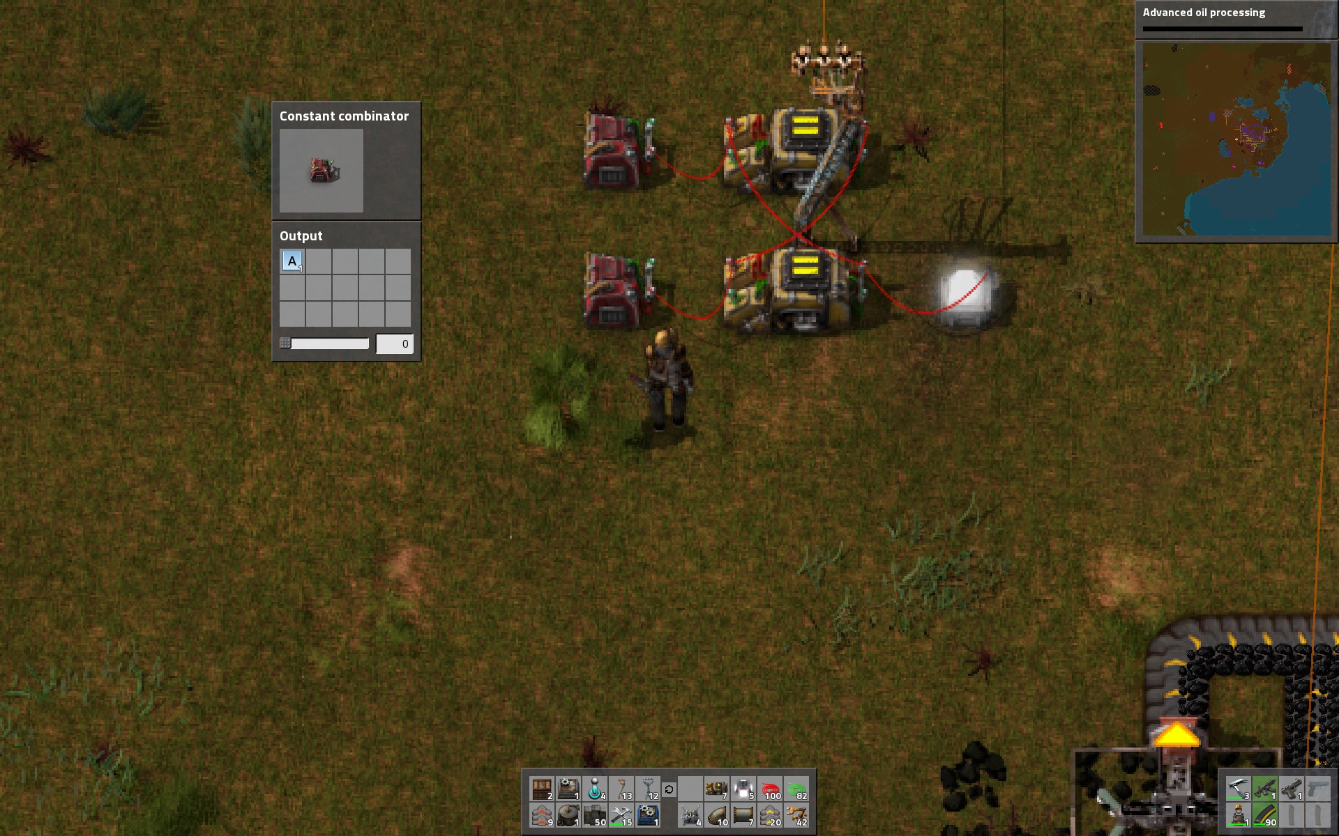
Wire Color Effects
Taking the Prototype SR Latch shown above and replicating it across two pair of SR latches, I found something interesting from wire color choice, which could have meaningful implications in more advanced logic. (NOTE: This was tested in v0.12.x. I have updated the content with pictures for v0.13.x to improve comprehension of this content– but I have not retested this behavior in the latest release. YMMV. Additionally, the order in which you connect circuit wires can have an impact when the set/reset signals are being transmitted on the wires prior to connecting the wires to the decision combinators. Any attempts to retest should be performed by setting Set value, then Reset value from the latch starting point. (Set=null, Reset=null.))
When both the Set and Reset values are true, behavior is different depending upon wire colors.
When using the same color wire for the DC1 to DC2 crossover as the inputs and outputs (i.e., all red wire, or all green wire), the SR Latch behaves as if the Set value is true. (i.e., Set has precedence over Reset condition.)
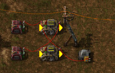
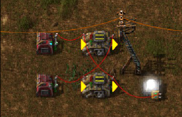
When using different color wire for the DC1 to DC2 crossover as the inputs and outputs (i.e., inputs and outputs are red, crossover is green, or vice versa), the SR Latch behaves as if the Reset value is true. (i.e., Reset has precedence over Set condition.)

DC1-output-green to DC2-input and DC1-input-red to DC2-output to Lamp gives the Set value precedence over the Reset value.


DC1-output-red to DC2-input and DC1-input-green to DC2-output (with the Lamp on DC2-output-red) gives Reset precedence over the Set value.


When only Set or Reset is true, the Set or Reset value works as expected. (See tables above.)
There would likely be additional interactions with more complex logic systems.
Liquid management and combinators
Small pump with a red circuit wire running from the pump to the feeding storage tank. The pump is facing away from the storage tank. Pump logic condition is set to “If Tank storage > 2,000 liquid.”
This behavior turns the pump on (pulling liquid from the storage tank) when the storage tank exceeds 80% (2,000 of 2500) storage. This ensures that the storage tank will never become 100% ful but will not become completely empty becaues of the Chemical Plants on the receiving end of the small pump.

Usage: If you want to Crack Heavy Oil into Light Oil (or solid fuel), you can do so while retaining some heavy oil to feed the Lubricant manufacturing. If you’d prefer to burn the oil off, you could connect the pump to a steam engine which will cause the steam engine to behave like a diesel engine and produce power while consuming oil.
NOTE: The point of this example is to show how small pumps can be triggered (on/off) based on logic conditions. This is an important point for the more advanced example below.
Small pumps point towards each storage tank. Circuit network is set up so that the small pumps only turn on when the current tank is not “full” but the preceeding tank is above the activation threshold (i.e., “full)).
This setup causes liquid to start in the Upper Right Storage Tank, then move counter-clockwise to the Upper Left, then to the Lower Left, then to the Lower Right, then back to the Upper right. Each pump will activate until the preceeding tank is virtually empty and then shut off, and then the next tank will activate.

The extra decision-combinators (DCs) are used to convert the input (storage tank level) to an A=1 or A=0 (no output) into the SR Latch pair of DCs. In this example, the pump is the output of this SR Latch, instead of a lamp.
NOTE: Rounding and tick delay will always leave a small amount of liquid in the preceeding tank. The water was input into the closed system via the 5th tank on the Upper Left. A small pump was connected to pump water into the Upper Left tank, and then the small pump was rotated (can be rotated without deconstructing) to ensure that no further liquid would pass through the pipe.
FAQ and final comments
- Combinators, pumps and other entites operate slower when there is a power brown out or blackout. This allows you to set up a complex closed water loop (less complex than the example above) where water is pushed back and forth between two storage tanks. As long as power remains constant on both sides the water levels will remain equal but as soon as one side experiences a power brown out of black out, the pump attached to that grid will slow or stop. This creates a water imbalance between the two storage tanks and can effectively be used to monitor power levels.
- Other combinator systems like pulses, timers, etc. will be covered in a separate guide. The point of this tutorial is simply to cover Set-Reset Latches in Factorio.
- Comment from Killcreek2 – flaws of this 2-combi design, ie: it only operates at 30fps, requires input pulses of at least 2 ticks length to properly latch [else it can enter a rapid 2-phase oscillation, mimicing a “race condition”], & is unsuitable to use with any sort of 1-tick pulse based circuitry [ie, digital computing].