
Overview
This guide shows how to combine the basic building blocks, namely the logic gates and timer elements provided in the BEE2 Portal 2 Puzzle Editor Mod, into more complex and novel circuitry. The few circuits presented and explained here can be used as a basis for even more complex elements.These complex elements can be used to create a new type of puzzle that exhibits an experience previously unseen.Putting the already supplied elements together is simple and straight forward.BumbleGrum
Introduction
The logic and Timer elements provided in the Portal 2 BEE2 Editor Mod give us a way of creating more complex elements by combining them together.
I started creating puzzles only a short time ago, and having come upon BEE2 and its’ wealth of elements, especially the logic and timer elements, it was inevitable that someone with my training and background in logic design would see the potential for further confusing the unwary.
I tried out a few things and found that they worked well, and sat down to nut out a few simple combinations that I will present and explain here. I have put together a number of basic building blocks that you can use to build even more complex logic.
Enough talk.. Let’s get to the basics then.
The basic elements
There are 4 basic elements that I will be using to build the devices contained in this document. They are the AND gate, OR gate, NOT gate, and TIMER.
Though most peple will have an idea what these logic elements are and what they do, I will describe each for the uninitiated.
For the logic gates, we will assume that initially all Inputs are OFF.
AND Gate:
The AND gate has two Inputs and one Output. The Ouput will only turn ON if both Inputs are ON. So the Ouput = Input 1 AND Input 2. Hence the name AND gate. When either or both inputs turn OFF, the Output will turn OFF.

OR Gate:
The OR gate has two Inputs and one Output. The Ouput will turn ON if either or both Inputs are ON. So the Output = Input 1 OR Input 2. Hence the name OR gate. When BOTH Inputs turn OFF, the output will turn OFF.

NOT Gate:
The NOT gate has one Input and one Output. The Output will only turn OFF if the Input is ON. So the Output = NOT the Input. Hence the name NOT gate. When the Input turns OFF the Output turns ON.

TIMER
The TIMER has one Input and one Output. When the Input turns ON, the TIMER counts down the preset number of seconds. When the countdown finalises, the Output turns ON momentarily.

Because of the nature of the TIMER element in BEE2, if the Input stays ON, the TIMER will count down repeatedly and trigger the Output. This is undesirable in most circumstances. In the following discussion I will present a TIMER element that only fires ONCE regardless of how long the Input stays ON.
Building Complex Circuits from Basic Elements
Firstly, I will present a simple circuit and then a modification of this circuit. The 2 variations will become the basis of all the other complex elements that follow.
Building a basic Latch
Although a latch is provided in BEE2, it has some undesirable traits, and for this reason I have choosen to provide my own built from an OR gate and an AND gate:-

When the Trigger Input to the OR gate is triggered, the Output will Turn ON. This ON signal will now mean that the AND gate has both Inputs turned ON and so its Output will also turn ON.
Now the OR gate has an Input that is ON and so the Output will remain in the stable ON state. The circuit has latched.
It may be desirable to be able to make this Latch turn off for some applications, so I present now a modification to the above circuit.
Building a Releasable Latch
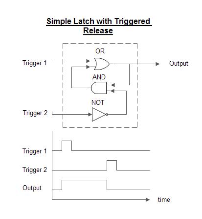
Should Trigger 2 be tripped, it will still have no effect. However, once the circuit is latched as described above, triggering the second input will turn OFF the corresponding Input at the AND gate invalidating its Output, which will now turn OFF, and providing that Trigger 1 has released, the circuit will unlatch.
I used this releasable latch in a demonstration chamber. The test chamber in the following link uses this releasable latch to enable and disenable the stairway to the exit door. Two triggers control the stairway, one of which is mounted on the stairway, and another located in an unavoidable position. These raise and lower the stairs. I wont tell you more, you’ll just have to figure it out on your own. Give it a try to see how effective these latches can be, then come back and read a bit further!
[link]A More Complex Circuit Element
As I mentioned elsewhere in this document, the TIMER element provided in BEE2 has the unavoidable characteristic of triggering multiple times. I’ve found that, in most cases, this is not what the needs of the map logic requires. It is more desirable to have a TIMER that, once triggered, counts down and fires its Output once only.
A One-shot TIMER (or Delayed Trigger)

So when the Trigger fires, the latch er.. Latches setting off the TIMER. Once the TIMER fires, the latch is released preventing the TIMER from triggering again.
Try the test chamber in the following link which uses this technique. Trying to get past the turrets is simple if you know the secret, and this text is a bit of a spoiler for this puzzle. but try it out and come back for more punishment!
[link]This leads us to the only other circuit that I am presenting at this time (I’ve got to leave something for you brainy guys and gals to invent using this guide).
Sometimes it would be nice to have the Output from the above TIMER stay ON once it is triggered and has counted down. We could call this then, a Delayed Latch.
A Delayed Latch

The operation of the TIMER circuit is the same as above except that once the TIMER element triggers, the output is latched ON.
This concludes my brief document. I hope it will be food for thought.
BumbleGrum
A Practicle Example
As a demonstration, here is the logic that I used in BumbleGrum 5. Try it first then return here to see how I did it. P.S. Don’t let the deadly neurotoxin get you.
[link]If you played the map and succeeded in opening the door, you found that there is only one sequence that opens it. This was accomplished using (big term here 🙂 ) Asynchronous Sequential Logic or ASL. ASL is a type of memory function. Here is the logic diagram that I used..
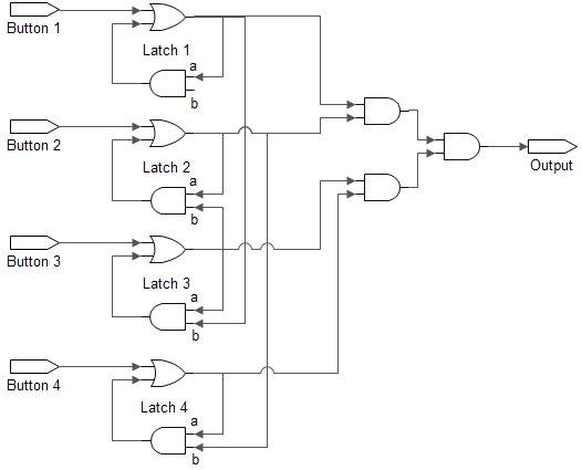
The logic works like this. At rest (i.e. As you walk in the door) the first latch is the only one where the b input to the latch’s AND gate (the [/i]enable[/i]) is ON. For all the other latches the enable is low. The latches can only retain their latched state if the enable is ON. So the first switch is the only one that will have an effect.
When this latch is activated, its output is channeled to the enable input of latch 3, thus enabling this latch. Latch 2 requires latch 3 to be activated, and latch 4 requires latch 2.
So the only sequence that will unlock the door is Latch 1 followed by Latch 3 followed by Latch 2 and then Latch 4 in that strict order.