Overview
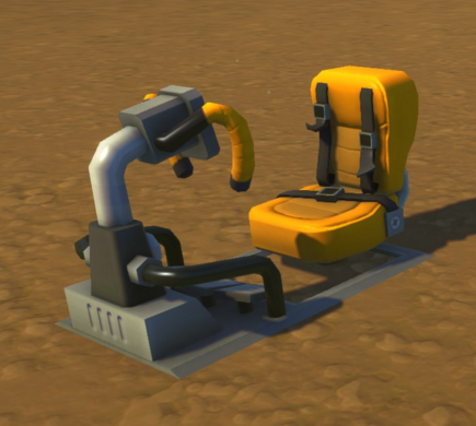
The drivers seat is only usually useful for vehicles. This guide will show you how to make a small machine to have custom outputs from the W-A-S-D keys using the drivers seat.
What is the WASD Converter?
The WASD Converter is a compact component that allows you to take the W-A-S-D input that the driver’s seat uses and turn it into 4 separate outputs. The component also has 4 controllers built into it, one for each output.
This was made because the driver’s seat is only really useful for land vehicles, and also because this allows you to have an extra 4 buttons when in the seat, so you have 14 in total, not 10.
Credit to my friend for figuring out how to change the input to work with a controller. All I did was compact it as much as possible.
I don’t know if a guide on this has been made before, but I didn’t see one so I figured I’d create one showing people how to make this component.
How it’s made
Equipment:
Step 1:
Create an area for the converter. The space required is 4×3.
Step 2:
Place a 2×3 area of a chosen material, then place Electric Engine on top, aligned the same direction. Place another 2×3 area on top of the engine.
Step 3:
Place 2 staircase wedges in the corners, and a bearing in the middle.
Step 4:
Fix a controller (or two blocks) to the middle bearing, and then put two sensors either side, attached to the electrical engine, as shown in the picture.
Step 5:
Place two blocks to connect the sensors to the staircase wedges.
Step 6:
Place a vertical controller in the middle if the two blocks placed in Step 5. Make sure that the controller is connected to the blocks and not the controller below, else it will turn.
Step 7:
Place two sensors on top of the two blocks placed in Step 5. Make sure they’re facing the electric engine, otherwise there will be player interferance when a player walks past.
Step 8:
Place a controller on top, as shown in the picture.
Step 9:
Get on top of the converter, and place a bearing in the middle, on the top-most controller.
Step 10:
Attach a controller to that bearing, and then place a block as shown in the picture.
(Optional) Step 10.5:
If you want, you can place two staircase wedges to make it look nice. That’s all they do.
Step 11:
Link the electrical engine and the bottom bearing together using the connection tool.
Step 12:
Put the electrical engine on a low power setting. If it’s at max, then it can glitch out and break. Just fine tune it to how fast you want it to detect. I’ve shown it at the 3rd setting in the picture, it’s a nice speed for fast reaction time and also allowing you to not have any sensor be active.
Now to link a driver’s seat to the converter, connect the electrical engine to the drivers seat and then the top bearing. If you press the directional keys, you should hear stuff moving and sensors being set off.
How it works
The converter works by moving controllers infront of sensors depending on what directional key you’re pressing. The sensors then will trigger and you can use that as an output.
Finale
If there’s ways to improve the converter, or if there’s something in the guide that needs clearing up, please comment saying so. 🙂


