Overview
A rather long write-up on advanced mode design theory featuring the Jupiter Sport Advanced Tech Starter Boat and Demo Craft.”Jupiter Sport”by UnTech Marine, a division of Untied TechnologiesThis guide documents the building ideas, logic, and overall design approach used to create my “Advanced Vehicle” career starter boat!The Jupiter Sport was the first advanced craft that I designed in this game, but it’s not the first thing I’ve designed. My goal with my first advanced craft was to create a fun and cool little performance-oriented boat that stays within the limited footprint of the small boat building area at the Starter Base. All of the key building blocks had to be available at startup so I could use the boat immediately to complete various missions.In this guide I go into a lot of design details, but this is NOT meant to be a literal “How-To Place Brick” style tutorial on building. The guide assumes you already have some basic knowledge of how to build things in the game maybe from playing and watching some other tutorial videos. It speaks more to the design ideas and concepts that went into the craft and I share my ideas, tips, and tricks that you may wish to incorporate in your own design methodology.If I mention something in the guide and you have a question or want me to add more details, just leave a note in the comments below and I’ll update the guide. This was the first boat I designed in the game; so feel free to share any suggestions you might have on the design and/or the design ideas that I’ve shared. I’m still learning too!
Hull Design
Took me a little while to get the sport boat shape that I was looking for and in the end it turned out looking pretty nice. One characteristic of this fast-boat hull style is they tend to run shallow and that long sweeping front cuts into a lot of hull airspace that we might otherwise have used for buoyancy.
IRL, the hull is designed to cut through waves and get up on hyrdoplane rapidly. I wanted that same performance from my boat in the game. In order to mimic this, I knew I had to keep as much buoyancy in the limited hull space as possible. So after I was satisfied with the hull shape, I went back and systematically deleted every single brick inside the hull that did not create a hull breach.

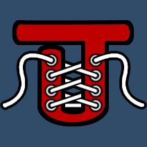
I started building inside the hull and as you might imagine, sometimes I put decks in at the wrong level and needed to move things around a bit. While I was doing this, I would sometimes forget that I added extra bricks to the hull interior that I didn’t really need. After having to reassess the hull a couple times for extra unwanted blocks, I decided it would be best to paint the interior of the hull a specific color so that I would always know which bricks were the outermost skin of the hull.
I decided to go with a custom light green primer-coat color (153, 255, 153). I liked this so much I plan to do it with all of my boat designs as I find it useful during the building process. …and I think it looks pretty cool when the boat is done too!
Due to the thin hull, the boat will definitely sink if you rake it across some submerged rocks at speed. I’ve had to ditch it on more than one occasion for this reason, but watching how it fails is kinda fun too. One time, after a nasty run-in with a reef… One of the engines wouldn’t quit and it kinda just cruised along half-sunk without me and just left me stranded there on the rock that I hit.
The Decks
In such a small boat design, you might not think in terms of multiple decks, but there are definitely 3 distinct deck areas on this boat. There is a forward, mid, and aft deck. The elevated forward deck is used most frequently during loading and unloading. The higher elevation makes it a little easier to jump onto other boats, docks, or stairways.
The middle deck is the primary area for storage and passengers and the aft deck is where refueling is managed. The two areas are separated by the Center Console pilot control area; the footprint mapped in the above photo.
The aft deck also has easy ocean access with ladders on either side to facilitate entering the boat from the ocean. I wanted the look of a no-slip surface on the mid and aft decks so I went will a dull gray high traction paint for these areas. The forward deck is going to be the same base gel-coat white as the rest of the hull.
Although passenger chairs and beds are among the starter blocks available, I do prefer the clean look of the empty decks until I have a specific mission where I might need to add a chair or bed. Several of my passenger ferrying missions have involved passengers just standing in the mid deck area and they don’t seem to mind.
I decided to add some white running lights around the bow and down each of the side rails. I temporarily marked them dark blue in this picture to make them easier to see against the white hull. However, they are white in the final design.
This was my first boat in this game and something neat that I learned pretty quickly is that you can paint the color of the lights to be any color you want. The default is white, but you can paint them red, green, yellow, blue… any color you want. In the photo above I selected the paint tool and to color the lights blue, I used the “Additive” paintbrush tool. You might also notice I installed some purpley-pink neon lights along the baseboards that should give a nice neon glow effect at night.
Tri-Marine Engines
This style of boat is synonymous with overpowered clusters of outboard engines. Not uncommon to see these cruising past the Jupiter Inlet Lighthouse (Florida) with up to four 300+ hp outboards hanging on the back; 40-50 knot top speed is a very conservative estimate.
Our little starting diesels don’t quite seem to be able to pack that much punch, but they are not too far off when correctly geared in advanced mode. Three of the starter diesels manage to push along the Jupiter Sport at a fairly respectable 40 knot constant pace. Interestingly, the top speed of our little boat actually improves in slightly choppy water where the hull likes to “skip” on the waves.
If you haven’t already noticed, the little diesels in our game are rather thirsty! The aggressive fuel consumption modeled in Stormworks puts a 100 km range completely out of the question. However, given the scope and play area of the game this is perfectly acceptable and (as I mention in my Fuel System discussion) understandable as a play balance mechanic.
- Hull Length: 53 blocks, 13.25 meters, 43.5 ft
- Top Speed: 40-42 knots
- Base Fuel Load: 1125 liters in 6 medium size fuel containers
- Auxiliary Fuel Tank: 3000 liters
- Max Range: 18/48 km (base/aux fuel) so 66 km is possible
For our “pseudo-outboard” Tri-Marine Engines, given the combination of: block size, building area, general aesthetics, and proportions of the overall craft… I decided an array of three engines would work best for our boat.

It is also worth noting the directional indicators on both of the rudders. You need to make sure you have the symmetry tool turned OFF so you can place the rudders individually. Otherwise, they move opposite of one another and you won’t be able to steer your boat.
With the inclusion of the outboard engines, 5 bricks were added to the overall length of the craft. So the length now completely maxes out the total building space available at the Starter Base small boat building area.
Engine Color Coding
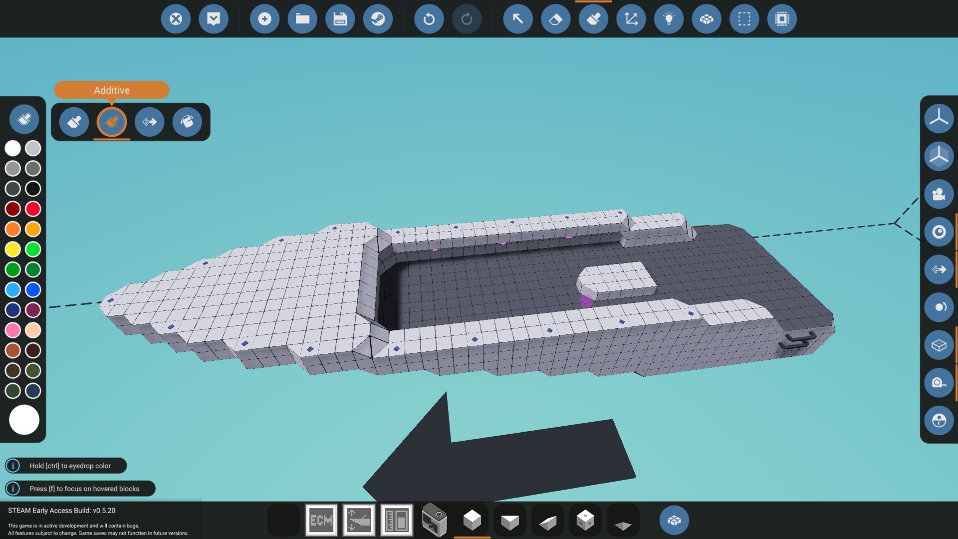
Very early on, and OK possibly after watching a Youtube video or two, it became apparent that the engine pieces and connective piping used to hookup engines needed to have an assigned color coding in order to keep things from getting confused. I’ve settled in now on what will be my standard coloring for all engine parts.
- Orange = Powertrain (engine, clutch, gearing, etc)
- Dark Red = Fuel Tanks and Fuel Lines
- White = (clean) Intake Air
- Black = (dirty) Exhaust and Battery Logic
- Light Blue = (cool) Coolant In
- Pink = (hot) Coolant Out
- Yellow = Specialized Control Surfaces
Granted, I also reserve the right to deviate from the above whenever the design or aesthetics may call for it. For instance, I have pipes connecting the outboard casing to the hull that are black to match the engine rather than white/black/orange to indicate purpose.
Although arguably not really an engine part, I did also use yellow to color my hydrofoils and the associated microcontroller. I could also see myself using yellow (think “yellow-iron” or construction vehicles) for cranes and various types of equipment and the associated logic controllers.
Given the above coloring, I might also paint wall blocks the appropriate color if there’s an embedded pipe of a certain type running through it. Although I didn’t use or need pumps for this design (the radiator might be a tad OP in this game, but don’t change it!) I would color them based on whatever they happen to be pumping.
If I use a single radiator on an engine, I favor the output color of light blue for the color. If I have an array of radiators (like a cooling tower) I might color them pink on one side, blue on the other, and possibly a blend in the middle to remind myself what is happening as the water enters and exits.

In my side testing of cooling tower designs and the largest diesel engine (obviously not used here) I was able to run the big diesel using a 1:1 gearing at full power with a 4-radiator cooling tower array in a very small footprint area. I stowed that bit of knowledge for later application. From what I’ve seen thus far, I rather prefer the use of radiators over powered pumps for engine cooling. I was a bit surprised the radiators worked with no efficiency hit in enclosed areas (zero air flow or heat transfer agent) but am happy that it works this way, although maybe not terribly realistic.
I monitor engine temperature on this boat with a single dial that displays Max Temp. My only concern is when the first (or next) engine might blow up, as opposed to which one. Averaging them together would mask problems, so I go with max value formula logic and report on the one that is running the hottest. Given the limited display area this works well. I also considered maybe putting a dial or indicator light (or two) on each outboard engine casing. Only problem is, this would cause me to have to leave my seat to see what’s going on back there and it really seemed more like novelty than anything, and the connections would further confuse an already busy logic screen so I dropped that idea.
Powertrain Design
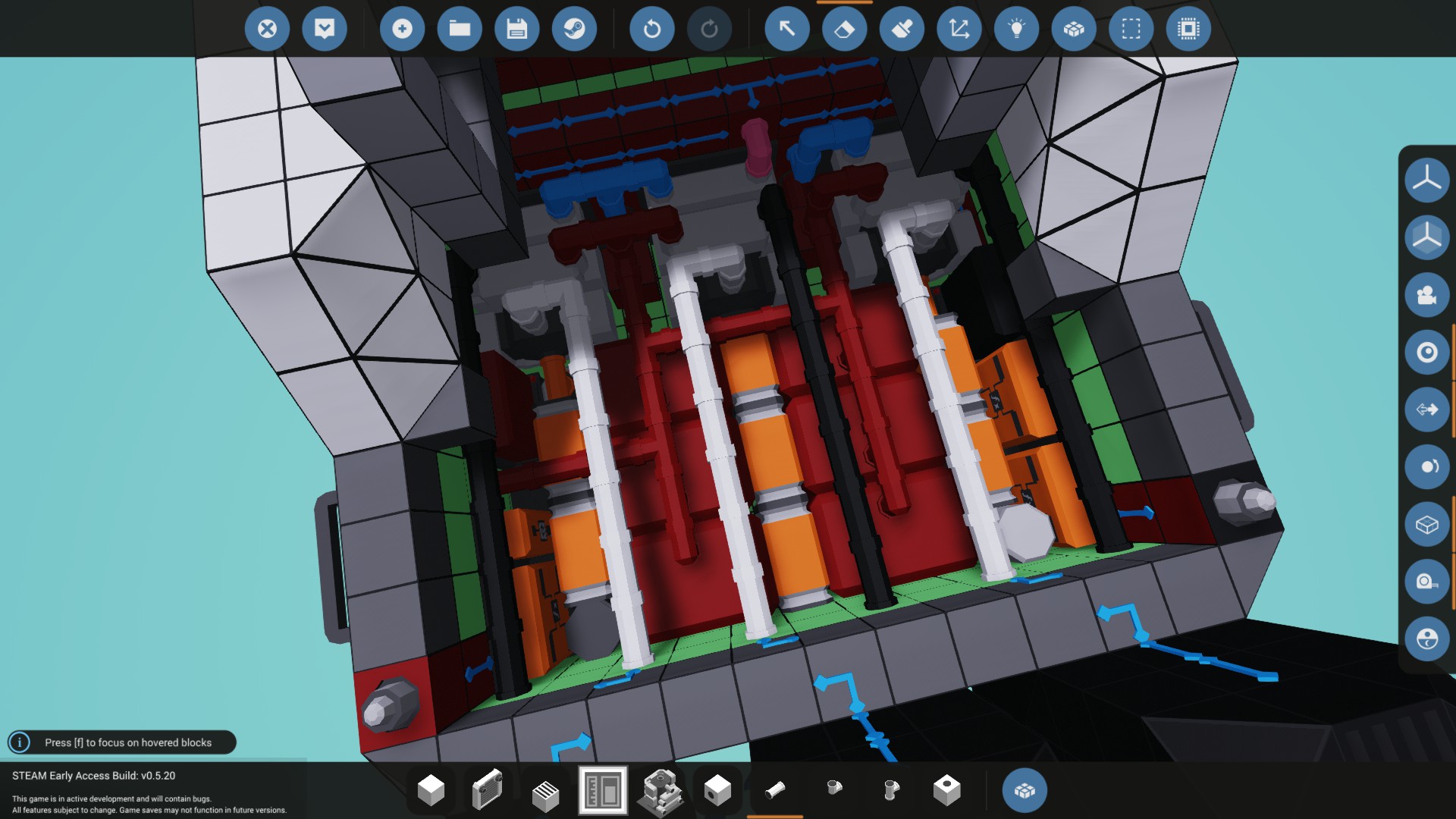
The typical engine layout for me will follow what I feel is a pretty standard form. Each of the 3 engines on my little starter boat are configured, at a minimum, as shown here.
First up is a little generator which produces low amounts of baseline power to run the various critical systems of my craft. In your family car this would also commonly be referred to as the alternator. I prefer the location of the generator to come before the clutch. Even at the relatively low 10% idle RPM, the generator provides enough power to recharge the batteries and keep the overall system power needs in check. Putting it after the clutch would be zero benefit, unless you put it all the way behind the gearbox, in which case it could generate more power in a higher gear, but potentially no power when the clutch is not engaging the engine.
What I don’t want to happen is, I make a quick stop for a box or something, leave the boat running on idle… hop out, get delayed a min or two, finally jump back in and the battery is dead because the generator is not producing energy due to the clutch not being engaged. At my chosen engine idle level, I should be making enough power to have my battery charge levels increase rather than decrease after starting up the engine. Try that out in your boat design, does your battery slowly recharge at idle speed after you start your engine? It should!
If you have no working knowledge of what a clutch actually does, I can see where it may not be apparent why it comes next in the powertrain. You can look at mechanical pictures of the thing, but I kinda like to think of it in terms of its name. I view it like a claw, or your hand sitting at the end of the engine’s spinning crankshaft just waiting to grab on to the thing so that spinning power makes it down to the propeller. When not engaging the engine, I think in terms of the clutch just letting go of the spinning crankshaft. That’s really all it does and the value between 0 and 1 represents the percentage of force that it is hanging on with. You could think of 50% like its only half gripping the spinning engine and turning about half as fast.
An engine will stall if the clutch grabs on to that spinning shaft too hard and too fast. The sudden jolt to the engine of having to do work causes it to shudder and stall. So what we want to do is make sure our engine is idling at a decent rate, maybe even give it a little gas to get ready, and then allow the clutch to slowly clamp down and make a transition from 0 to 100% engaged.
This also explains why any generator installed after a clutch would not produce any energy when the engine is sitting at idle and the craft is not moving.
Next comes the gearbox or maybe a series of gearboxes? This is where you have gearing applied that causes the shaft to spin faster but puts more load on the engine. The small diesel might spin up to 1500+ RPM with zero load applied, but once the clutch is engaged and the engine has work to do, you probably won’t see the max RPMs go so high.
Gearbox direction is important! Pretty neat that the gearboxes can be installed two ways. Typically, people are looking for more speed and fuel economy, so they would want to install the gearbox as I have it shown above. Notice the blue arrows on the gearbox are pointing at the engine. This should cause a decrease in torque (less low end power) but an increase in SHP for more speed and better fuel economy over distances. I like to think in simple terms, so if I want a fast speedboat… the gearbox is going to point toward the engine. If I want a slow but powerful tugboat that can move large objects (slowly) then my gearbox is going to point away from the engine.
Above I mention SHP, which I’ve come to define as Storm Horsepower which is RPS * Torque, the two elements that a Torque Meter tracks. I could put the torque meter anywhere in the powertrain to see how power is being converted before and after gearing and so forth, but for my boat… I’m really more interested in how much power is getting to the propellers.
Some might ask what the difference is between Storm Horsepower and just Horsepower. I’ve looked, but I can’t find any reference to tell me what base the Torque output is being calculated in. I know it’s not the traditional imperial foot-pound force as everything else in the game is metric, so rather than guess at it or dividing by 5252 (which I know is wrong) I figured it’s just best to use the two raw numbers as provided by the Torque Meter and assume that was the simple intended purpose. Coincidentally, SHP is also a common abbreviation for Shaft Horsepower, as opposed to Engine Horsepower… So that makes sense too, I’m taking the reading after the gearbox so it is a shaft horsepower type calculation.
I don’t really see a need to install a torque meter in front of the gearbox. If you have in mind the idea of creating automatic transmission gear shift logic, as I have on this boat. The output you would monitor to determine when to shift would be the RPS or RPM of the engine itself. And that info is available on the engine without having to install the extra torque meter.
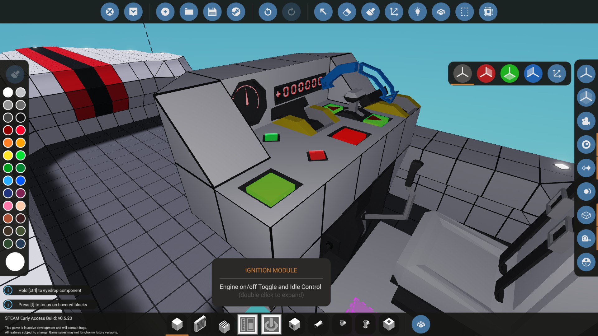
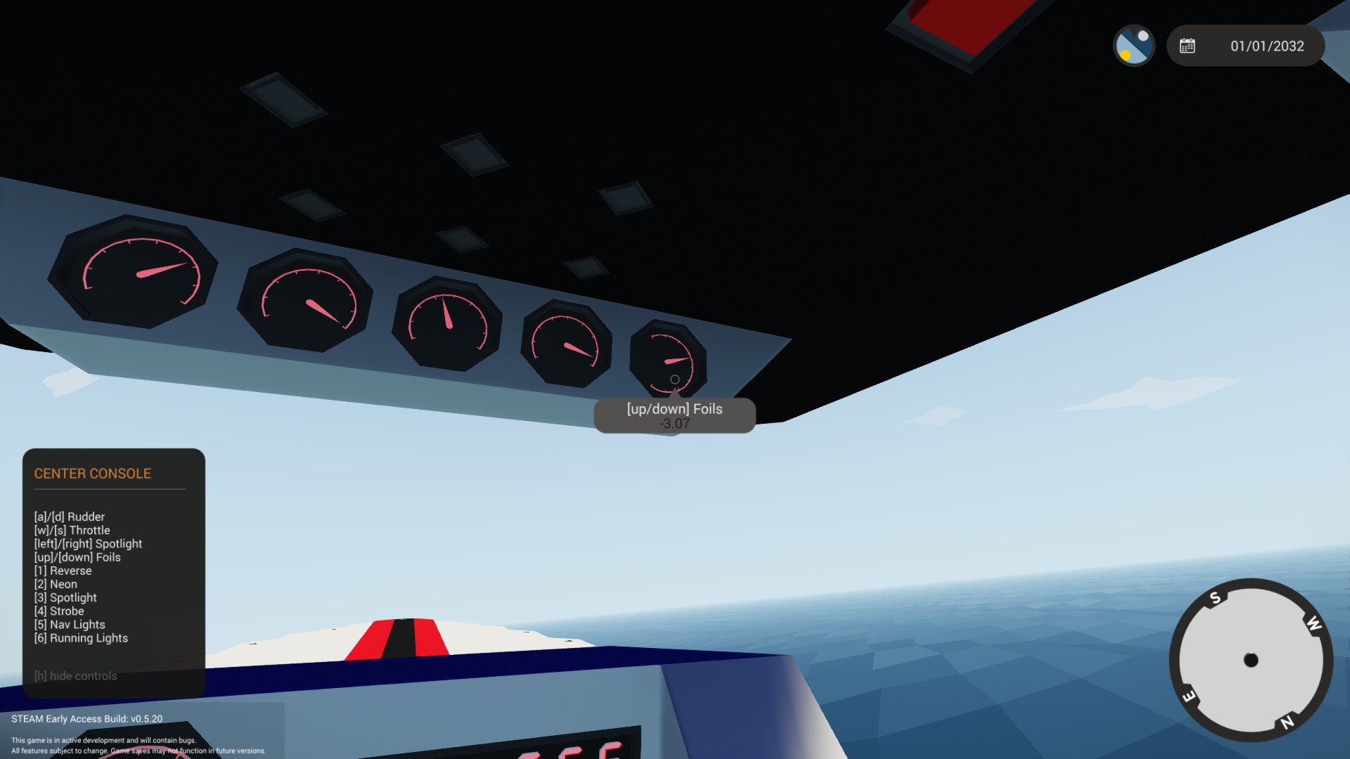
Center Console
The Center Console includes an upper and lower area for various dials, controls, and toggle buttons. Everything you need to run the boat can be reached from this location. In the photo below, you can see that I’ve labeled every control on the Center Console. One additional thing I also like to do is add the keyboard keys to any dial or button description they may be associated with. For instance, when you mouse-over my Reverse button you see “[1] Reverse” to remind you that 1 is the keyboard shortcut for Reverse.

- Green On/Off Engine Ignition Toggle Switch
- Avg RPM Dial
- Green Overdrive Indicator Light (related to RPM dial)
- Red Master Power Light
- Digital Display showing SHP (see my powertrain discussion)
- Master Power Switch
- Reverse Toggle Button
- Throttle
- Aux Battery Switch

- 5 Light Toggle Buttons: [2] Neon, [3] Spotlight, [4] Strobe Light, [5] Nav Lights, [6] Running Lights
- 3 Red Engine Stall Indicator Lights (if one is on, an engine is NOT running)
- 3 Yellow Warning Indicator Lights for: Low Battery, High Temp, Low Fuel
- 5 Dials for: Speed, Battery, Engine Temp, Fuel Remaining, Foil Position
So logically, the 3 yellow indicator warning lights are associated with each of the dials they are above. The 3 engine stall warning lights should be lit-up before you start the engine, and then all go off once engine idle RPS levels are detected. The engine most at-risk for stalling is going to be the middle engine. It’s the only one that I setup with an extra gearbox to go in reverse. I use the extra space in the powertrain on the other two engines to run dual alternators.
Note to Devs: it would be nice if those 5 overhead toggle buttons did not all appear red when toggled off. Ideally they might be a darker “unlit” shade of the “Additive” paintbrush color that was applied for the light. However, I’d happily settle for the plain grayed-out approach you took with the indicator lights. I don’t like unlit toggle buttons that appear red and then light up green.
The startup sequence for this boat is fairly simple. Throw the Master Switch to see the red “Power” indicator light come on. Hit the Engine Ignition Switch… wait a sec for engine to start. Blast forward at full throttle!
Throttle can either be controlled by pressing the buttons on the throttle controller on the Center Console or by using the w/s keys on the keyboard. I like adding these inputs together so I can use my throttle controller like a cruise control and the w/s keys as an override. This lets me come to emergency stops pretty easily (to pick up a crate or two) and can be handy for maneuvering slow near docks.
I did violate one of my starter boat design goals with the “Speed” console dial. At the beginning of the game, the Linear Speed Sensor is not available. So when you spawn the boat it will say the part is missing. I have it located in the hull and you can see where it will be when you do get it. This was just such a fundamental display dial that I had to setup the place and logic for it. This is the only missing piece and once you do get it, the next time you spawn the boat, it’s installed! I know the cruising speed is 40 knots at full throttle so not really required… but I like to see if I can tinker with the hydroplane stabilizers in waves to get the boat tuned to go a few knots faster.
Electrical System Design
Granted, I didn’t search too hard on Youtube and there might be some discussion or tutorial out there covering actual electrical system layouts and design; as opposed to, “Here’s how you connect power to stuff.” I would think a good tutorial on the usage of the Electric Circuit Breaker and Electrical Relay might cover the concepts. The following is a quick overview of how I intend to manage the electrical systems in all of my designs.
Most of the tutorials I watched were really focused on other elements of equipment layout and design. The electrical systems employed in these examples typically involved attaching a singular power source to every power-needy device on the screen as rapidly as possible by just ctrl-clicking every device, which then resulted in a fan of yellow lines all radiating from the singular power source. After watching 10-20 such examples (although certainly not intentional) I can see where people might begin to conclude, this “Electrical Fan” approach is just how its done.
Although it might work, the “Electrical Fan” shown below is not a particularly useful electrical system layout choice.
I should pause briefly to mention how the basic electrical connections work. You click-n-drag one yellow plus to another. It was not immediately intuitive to me that disconnecting an electrical/logical link required the exact same action as making the connection. It works like a toggle. Now it all seems logical, but I did have to ask how to disconnect the electric/logic connections without having to actually delete the associated piece of equipment. Also very helpful to keep in mind that holding down the Control Key while clicking and dragging the electrical/logic connectors around allows you to connect multiple things without “letting go” of the connector, which is quite handy.

I do have some knowledge regarding the operation of boats and small aircraft and one design element that just seems very fundamental to me is the idea of a Master Switch. We get spoiled by our personal automobiles not having such a thing, but this is a pretty standard design for small boats and aircraft. The Master Switch separates the battery from every other piece of equipment on the craft. The first and last step of any startup/shutdown checklist is always “Master ON”, “Master OFF”. A pilot of a boat or plane that forgets to turn that Master off when handing in the keys might be subject to a fine or penalty from the boat/plane owner for needlessly running the battery dead.

I view and treat the electrical connections differently than the logic connectors. Rather than an “Electrical Fan” I try to setup the electric connections the same way you might connect equipment with wiring. I string my bank of batteries together and then create one link between my main battery bank and the “B” terminal (B for battery) of the Circuit Breaker. I use the “A” terminal to then connect all the equipment on the boat. However, I do still follow a wiring-type process when linking equipment to the A terminal. I might string together the dials on my Center Console and have one link to those, another for each engine and associated power train, then control systems like rudder and hydrofoils.
A more organized “Electrical Network” approach to managing power storage, producers, consumers, and various interconnected systems.

On this boat, I wanted an emergency backup power system. You may have noticed I added a second Electrical Breaker Switch on the Center Console to the right of the throttle. I use that to control an auxiliary battery bank for backup power. It’s wired just like the Master Switch; backup batteries connected to the B terminal and then I connect the A terminal to the Master switch A terminal. This lets me add backup stored power to the system anytime I want with the flip of a switch.
Although not directly related to the electrical connections; but rather, the logic connectors. A subtle but neat little design element relates to the instrumentation backlighting. When you review the logic connections notice the on/off connections for instrument backlighting are all wired to the Engine on/off toggle switch. Start the engine and the instruments all light up! It’s a cool little effect that gives me the feeling my boat has come to life. …and another reason I like the Toggle Button for engine ignition.
Engine Ignition Module
Ahhh, Engine Ignition…
I had a lot of fun stumbling my way through this one. From what I’ve seen and seen suggested (particularly in Discord chat) a lot of folks don’t handle this very well at all. And at first, neither did I.
As I started building engines in advanced mode I made what seems to be a very common mistake. I used a Toggle Button to start the engine. It just made sense to me because I thought in terms of the button being an “Ignition Switch” as opposed to just an “Engine Start” button. I wanted the engine to stay running so a Toggle seemed logical.
If I used a regular “Push Button” the engine would just die; so I figured that must be because the button had to stay engaged for the engine to remain on. Like it was controlling the actual cylinder ignition. Cut the power, kills the spark plugs, stops ignition. Made perfect sense.
So, the Toggle Button was my first choice. I also liked the idea of the toggle button lighting up green to indicate the engines are running. Recall, I had figured out how the “Additive” paintbrush tool worked to make that light green instead of red. When I toggle the button off, the light goes out and the engine dies. Works perfectly! …or so I thought.
There were a few glaring problems with my early misconceptions:
- When I tried using the regular “Push Button” to start the engines, the engines were NOT dying because the button was not being pushed!
- At one point, while playing with my spiffy boat, I toggled off my engine… and guess what? The engine would not stop running.
- Finally, and probably worst of all… When you hookup a button to that “Start” node on an engine, you are literally engaging a built-in starter whenever you press the linked button. If you misuse a toggle button it will continue to crank that starter as long as the button is pushed or toggled ON and it draws a LOT of battery power.
At some point, I had mentioned in Discord chat that I had a Toggle Button on my engine and I think the general reaction was, “PFFffft… NOOB! Never use a Toggle Button to start an engine! Just don’t do it. NO.”
I love my Toggle Button engine starter. Must we say goodbye?
So I did reluctantly go back and scrap the toggle button shown above. And came up with a more acceptable push button design. However, I really liked having that “Engine On” light. So I added an indicator light. But then I had to come up with some logic to determine when the engine was actually ON. So I added a Logic Threshold to watch the engine RPS and if it was above a certain level, the engine light was ON. But then I also needed something to make the engine stop, so I added a “Kill Switch” …and I just did NOT like this at all! It was causing me to take up 3 spaces on my Center Console instead of one and I still felt like my Toggle Button should be able to manage all this in a single square.
I happily went back to my original Toggle Button design as shown. But this time, it would be different. I understood why my engine was originally dying with the push button. It was because I had too much load on the engine due to poor management of the clutch. This would cause the engine to instantly stall as soon as the starter was not firing. Remember, my Toggle Button was causing the starter to be ON all the time; so it was just constantly restarting the stalled engine, but I had no idea it was happening. I thought the engine was just running. In hindsight, it was a very sloppy design and the battery drain was appalling.
At this point I had built a number of logic-based systems for my boat and even a few custom micro-controllers (actually there are 5, err well maybe 6 or 7, I combined a few in the ECM) so I was confident I could create a solution. I designed the following rather simple “Ignition Module” micro-controller to do exactly what I wanted.
Examining the logic above, you’ll notice the duties of the Ignition Module are as follows:
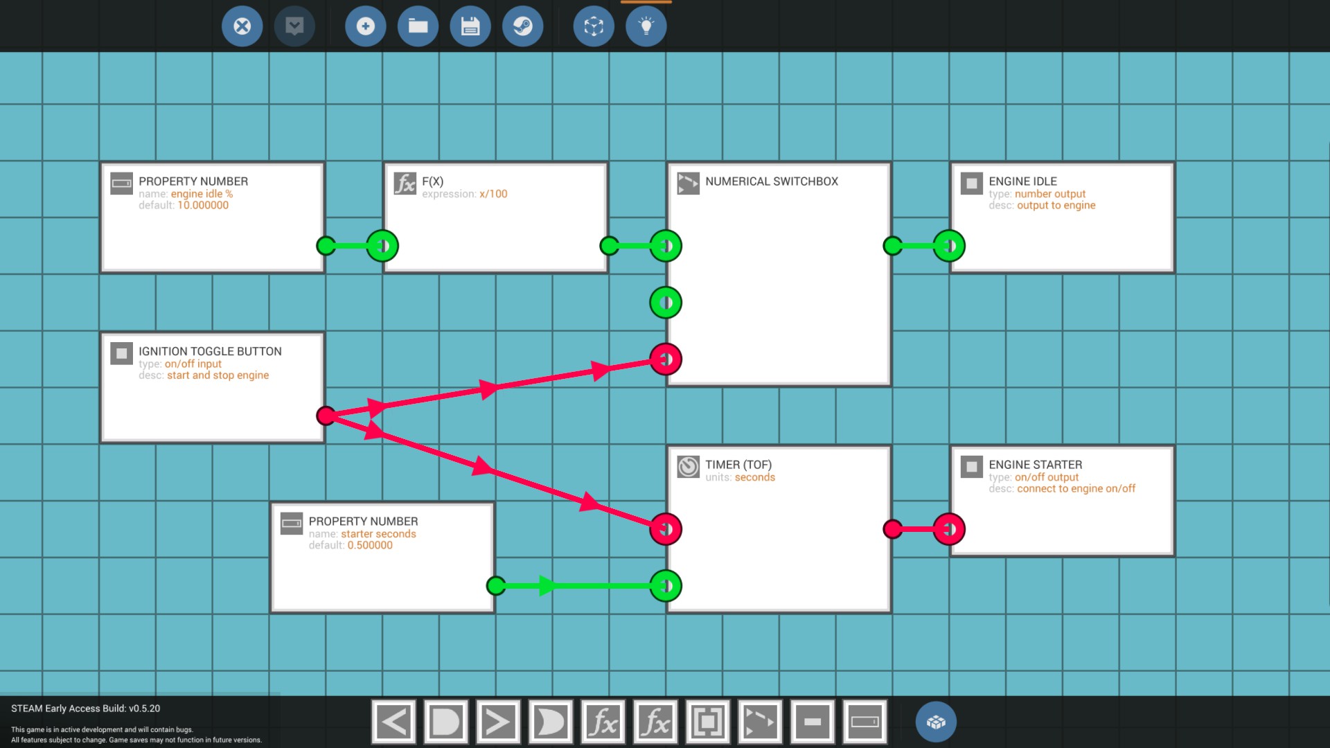
- It’s designed to be used with a Toggle Button
- When the Toggle is ON the starter is engaged for 0.5 seconds to start the engine
- The Toggle Button remains ON to indicate the engine is running, but it doesn’t keep sending the ON signal to the Engine Start node
- A default value of 10% is assigned for the minimum engine idling throttle level
- When the Toggle is OFF, the 10% idle is reduced to zero and the engine dies, notice the Numerical Switchbox has no value (or zero) assigned when the Toggle changes to OFF
This works very well and saves space on my Center Console by eliminating the need for an extra “kill switch” and “engine on” indicator light. I use the Toggle Button to Start/Stop the engine and while the engine is running at an adjustable 10% idle, the toggle button is lit up green. This is the only control on the console that can take the throttle all the way to zero to kill the engine. Logically, it does require you to have the main throttle set to zero though. It only cuts the portion of the throttle allocated to engine idle.
Engine Control Module
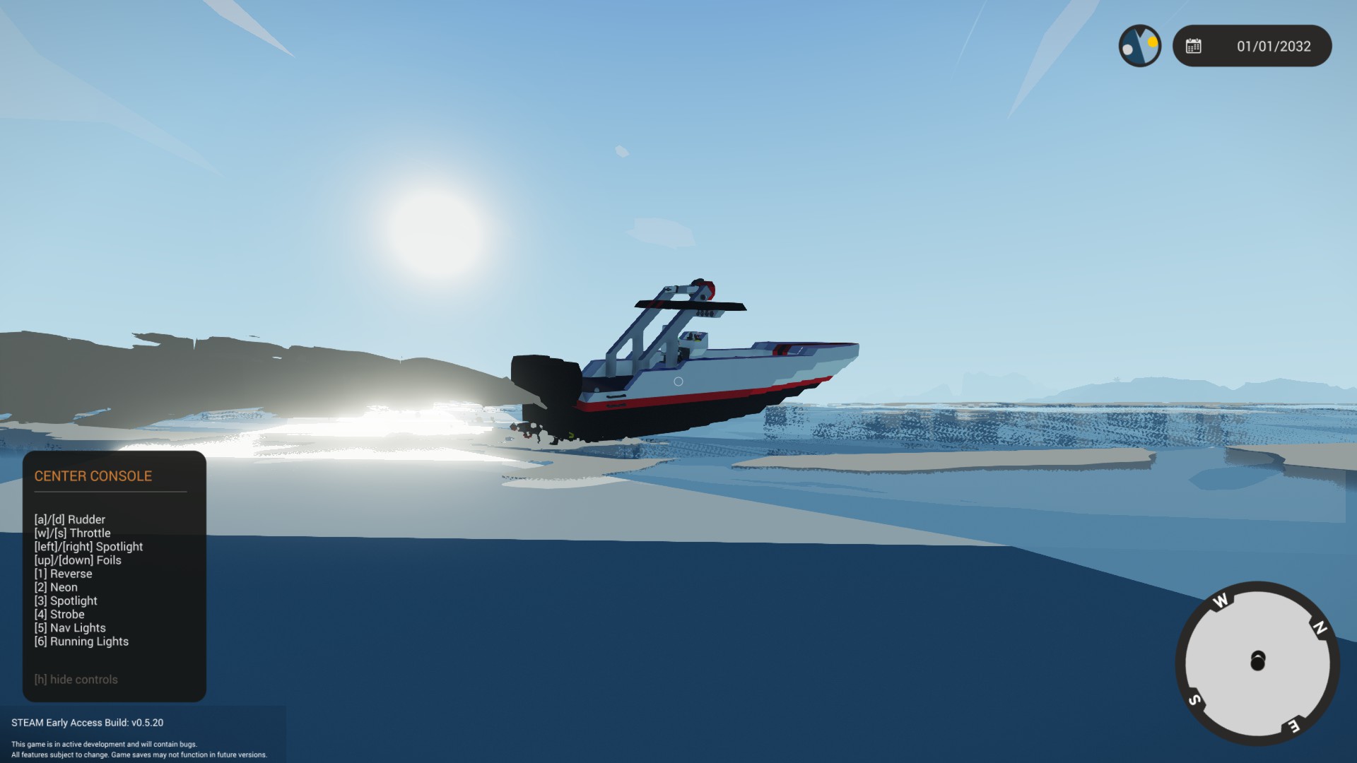
The ECM was absolutely THE first thing I knew that I wanted for this boat. On the Jupiter Sport, the Engine Control Module is at the heart of the performance feeling that makes the boat fun to drive. It’s still a starter boat, but considering its running on three little diesels the top speed is certainly respectable.
The ECM is responsible for the automatic control of the clutch, gear shifting, and reverse engine settings. Gearing includes a high-torque 1:1 ratio for low-end power and rapid acceleration through 1100 RPMs. At 1100, the hull is up on plane and the gearing automatically up-shifts to 1:3 ratio for sustained “Overdrive” cruising at about 40 knots and 700 RPMs. There is also a green Overdrive indicator light on the console right below the RPM gauge that lights up when the higher gear is activated. The lower RPMs translate to fuel economy and you’ll want to spend as much time as possible at full throttle in order to keep your max range at 18 km with your base fuel load of 1125 liters. (65+ km if using the 3000 liter aux tank)
Carve sharp into a turn and the ECM will detect the RPM drop and automatically shift down for power to get you back up on plane. When fighting large waves in a small boat, you’ve got to have that low-end punch to keep moving and the last thing you need to be thinking about is controlling the clutch and shifting gears.
The MC logic on this one is a bit more involved and was actually the combination of two (maybe 3?) separate controllers. You can see on the image below, the upper gear shifting logic and lower clutch controller and reverse management logic are completely disconnected and could each reside in their own controller. I chose to combine them mostly to manage the input/output footprint. If separate, one would take 7 block spaces, the other 2. Combining them gave me a conveniently sized 3×3 9-block square.
The “Upper MC” gear shifting logic now visible below… You might notice I state the input variables for up/down shifting as RPM as opposed to RPS. That’s because the dials on my boat report RPM and it’s the number I’m looking at while driving it. I don’t really think in terms of RPS so I don’t put it on my gauges.
And the “Lower MC” clutch controller and reverse logic…
Overall, I’m pleased with the efficiency and logic of the gear shifting… Likewise, the automated clutch controller and ramping works well. Trying to mesh that in with Reverse logic was a bit messy (the fan of red lines) and I may continue to work on that aspect.


The logic manages the transition from forward power with all three engines to a slow and controlled reverse gearing with the single center engine. Doing this without losing an engine in the process required some careful throttle and clutch mapping along with a bit higher revs on the idle setting. You’ll want to throttle all the way back before shifting into reverse, else you will surely stall the middle engine. There is a Reverse Power % setting tied to both the throttle and clutch. It is set to 30% by default and I would not change it.
The higher 10% default setting for engine idle (managed by the Ignition Module) does help to keep the single reverse engine spinning, but you still have to go easy with your reverse shifting. A lower 8% idle worked; at least until I tried to put a spinning prop into reverse. At 8%, the engine just doesn’t have enough revs to overcome it and 10% seems to more reliably do the job. You will stall the middle engine throwing it into reverse at speed so watch your overhead engine stall warning lights and drive it like you actually had to pay real money for your engines and you’ll be fine.
In addition to managing the gearing requirements, the ECM includes an automatic clutch controller with linear mapping tied to throttle position. Adjustable properties include the percent throttle position where the clutch begins to ramp-up engaging the engine and the range required to ramp up until the engine is fully engaged. The default settings have the clutch starting at 10% and ramping up over the next 70%. So anything between 10% and 80% throttle would have the engine partially engaged.
To make a long story short… Once you start the engine, all you really need to do is punch the throttle and go!
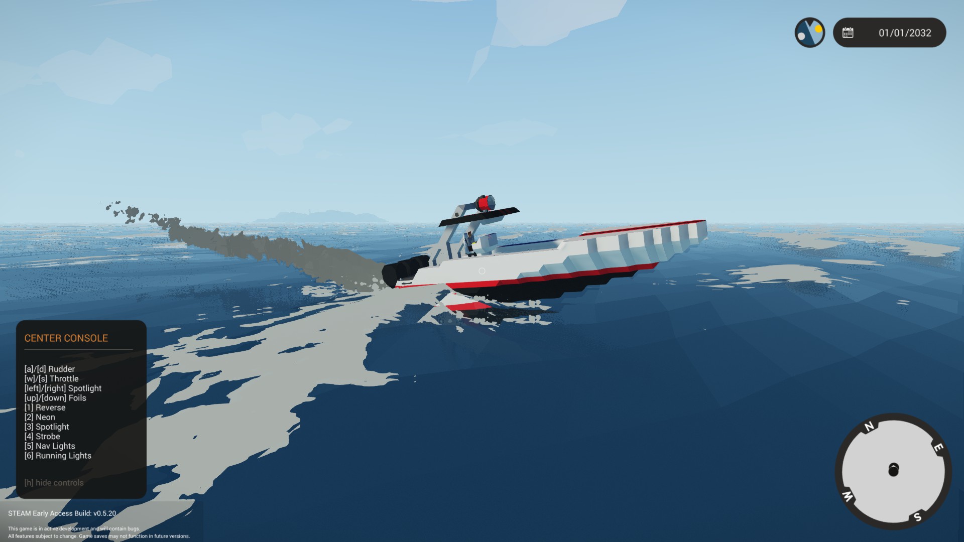
Hydroplane Stabilizers
As mentioned, this style of “go-fast” boat is intended to get up on a hydroplane quickly to operate at maximum efficiency; skimming and skipping along the surface of the water. Frequently, hydroplane “foils” are included either on the outboard engine, or the boat itself in order to control the pitch angle of the nose of the boat at high speeds.

At first, I setup the up/down arrow keys as “Sticky” in the pilot chair settings and just attached it to each of the foils. I took the boat out for a spin and it worked great! I think I had to change the orientation of the rudders once so when I used Down Arrow the nose of the craft came up instead of going down. I also noticed the range needed to be limited so I had to add more logic to keep it within a max range of 10% up/down angle. …but otherwise it worked as intended and actually performed very much like the real thing. Everything was great!
And then I decided to perform a high-speed turn. The boat did not carve a wave at all. The shallow hull in combination with forward momentum caused the boat to roll away from the turn instead of into the turn. It didn’t feel like a performance boat, and frankly it looked stupid. In waves it had trouble coping (battling) with unwanted roll. I had to fix it.
The solution was the HPS Controller. The idea for this micro-controller was to continue to manage the up/down foil position with the arrow keys, but also allow an adjustable percentage of rudder control input to be translated into roll control for carving turns using the hydrofoils.

There is also an adjustable “Reverse Foil Position” property value with default set to “zero”. If your boat includes a Reverse toggle button (as this one does) the foils will automatically snap to zero position when reverse is set to ON. It also reverts the foils back to their prior position when Reverse is OFF. For this to work, a Reverse on/off input is also included on the micro-controller that is tied to the Reverse toggle button on the Center Console.

In high seas the roll stabilizer allows the boat to counter the effect of large waves rolling the boat too far and capsizing. Although it is still a challenge to take a boat this small out in 100% wind conditions, it will hold its own up to about 80%. You can survive in 100% wind, but it’s definitely a challenge!

Fuel System
There were some compromises that I was somewhat pushed into as a result of not having access to certain building blocks for a starter boat. Additionally, individual play styles that may or may not involve the “Limited Fuel” setting also weighed into the mix.
We should however, start the discussion of the fuel system with what must be a very obvious statement to anyone who’s tried to complete a mission in this game with their own boat. The engines guzzle fuel at an astonishingly high rate! …even with gearing set 1:3 for lowest torque and best top-end fuel economy, the operational range of craft is rather limited.
To put this in proper perspective, take a look at the spec sheet for the 39 ft fast-boat design, Interim Midnight Express[www.cbp.gov] operated by US Customs in South Florida. It’s outfitted with four 300 hp Mercury outboards capable of sustained speeds at 60 knots with an operational range of 400 NM or 740.8 km!
In stark contrast, I have my Tri-Marine Jupiter Sport with 3 smallish sized engines (each probably not too far off of a real life 250 hp outboard?) that gets me to 40 knots with a base fuel allotment of 1125 liters; yes, a whopping 300 gallons of gas. …and with that combo, I manage to eek out a maximum one-way operational range of 18 km!!!
On the one hand, fuel burn rate may very well be the most egregious transgression of reality in the game that I’ve come across thus far. But on the other… It doesn’t really bother me. I just view it as a gameplay balance mechanic. If you didn’t burn fuel at an unreasonably high rate, you might not have to put as much effort into oil-for-diesel trade arbitrage schemes to keep your little SAR business afloat. So yes it’s entirely ridiculous, but managing the always dwindling fuel resource is also part of the fun.
The area of a single building block in this game can hold exactly 15.625 liquid units. With this bit of info, you can determine how much any pre-built tank can hold by simply counting the number of blocks it occupies and multiplying by that 15.625 base amount. The Medium Tank available at the beginning of a career for instance takes up 12 blocks of space. So its liquid capacity is: 15.625 * 12 = 187.5 liters.
I started by installing 6 of these (2 for each of my pseudo-outboards) and that gave me 6 * 12 * 15.625 = 1125 liters. Running at 1:3 gearing, my range wasn’t the best at 18 km, and I had room to spare in the hull. So if 6 of those Med Tanks will do 18 km, then adding 12 more (18 total) should get me up to 54 km operational range. So that’s what I did, and it worked fine. And then…
I decided I’d have a go at this Limited Fuel setting for a career. It spawns your craft without fuel and you have to fill your tanks with the starter amounts on each base. Sometimes buying new bases for no other reason than to plunder its fresh diesel supply in lieu of not being able to actually locate any source to purchase the diesel from.
One gameplay balance tweak that I might suggest to the developers is to watch the value they are selling the Island Bases for. It should not be cheaper for me to acquire several thousand liters of fuel by buying an entire island facility; than say, going to a diesel pump and paying for fuel. There’s an island I can buy for instance for $10k and it comes with what? 13,000+ liters of fuel? At that price, I would’ve gladly paid $10k just to get the diesel it had in a storage tank. Of course, I am guessing a bit… I haven’t actually played long enough in a career to find an island to buy diesel from. (LOL) I assume it might cost a dollar or more per liter? I can’t really tell, the sale price of diesel seems to be bugged at the moment. But I digress…
So back in my “Limited Fuel” career I spawn my boat with 18 med tanks capable of holding a whopping 3375 liters (891 gallons!) to carry me 50+ km if I should so choose. The boat does still manage to float with this fuel on board by the way! I hook up the hose to fill the tanks… and… OMG… the flippin fuel flow rate! I could suck liquid faster through a coffee stir straw. I wait probably a good 20 to 30-ish minutes. I’m gonna have to start logging this to deduct against my actual stated gameplay time. Think I wandered over to Discord chat while waiting.
Finally! The boat is fueled. But I am NOT doing that again, it was NOT fun. This fuel flow issue might be the next most egregious thing I encountered in the game, but this time the devs maybe should look into fixing the pre-built tank fuel flow. I’m OK with the fuel guzzling engines, but to be fair, I’m also gonna need fire hose pressure to fill all these tanks you are making me install. There are some time sensitive missions that I can’t even take because it takes me half of the stated mission time to put fuel in my boat.
Now something I did learn is that (for whatever reason) fuel flow rates are far better if you build custom tanks. With this in mind, I scrapped the extra 12 tanks I added, and added an even larger “Rum-Runner” secret storage tank to the middle of the boat. Turns out, this starter boat wasn’t actually purchased new for my SAR startup venture. I got it at auction down in Miami after it was confiscated by US Customs in the Florida Keys. Not sure what exactly they were carrying in that hull space before, but now it is capable of holding 3000 liters of what ever tasty fluid I wish to carry. So max capacity for the boat is now 4175 liters (1100 gallons) with a max range of 65+ km. At some point, I guess I could classify it as a tanker.
The idea did occur to me to completely drop the 6 pre-built medium tanks. Only problem is… Although the career starter block set includes access to the required Fluid Ports to create a wonderful and functional custom fuel tank, the starter blocks do NOT include the block that allows you to spawn fuel in this awesome tank if you are not playing a “Limited Fuel” career game. So if I put this design out there with a custom tank. I’m basically forcing people to kinda play a half “Limited Fuel” kinda game. I mean you can spawn a tank of fuel to refuel your supply tank, but that’s kinda not something someone might want to bother with if they are specifically NOT playing with “Limited Fuel” turned ON. Another negative is that the block that allows us to check the fluid levels in a custom tank are not available at the start of a career either, so there is no simple way to know how much fuel remains in the custom tank.
A compromise, I thought, was to have both. I have the base 6 med tanks at 1125 and the reserve “Rum Runner” tank at 3000 that always spawns empty. You can upgrade it later with a fuel spawn brick (when you find one) if you want to and outfit it with the missing fluid level indicator that would also be needed. Having this combination custom and pre-built fuel system also led me to create yet another micro-controller.
Amount Remaining Microcontroller
The “Amount Remaining” Microcontroller

The controller logic takes unit volumes of two sample tank amounts remaining as inputs (12 for med tanks) and then a total number of units in the overall system. In this case 4125 L / 15.625 = 264 brick unit total capacity. In conjunction with an input for the 15.625 constant it can then make a decent guesstimate on the overall fuel level of the system assuming the fuel sloshes around and distributes itself among the various tanks.
I made the 15.625 base unit amount an adjustable property so I could use the Amount Remaining controller to sample and calculate amounts remaining in other systems that may have other base units. I also use it to measure battery levels and just set a value of 1 for the base unit, and 1 for the unit size regardless of how much area the batteries might occupy. Arguably, for measuring batteries, you wouldn’t really need this. However, the controller also has a “Low Fuel” indicator built into it with an adjustable threshold amount. I like using it with batteries for this reason alone. I didn’t really see a need to build extra logic just to manage a “Low Battery” indicator light if this will cover it.
When I tried the 4125 L fuel system setup, fuel flow on pre-built tanks proved to be a bit of a problem once again. The 1125 liters spawned in the 6 med tanks, which caused my two sample tanks to read as FULL. So my fuel gauge reports 4125 fuel available. The fuel begins to very slowly spill into the Rum Runner tank and I watch the 4125 steadily decline. The dribbling fuel equalizes so slowly between the tanks that it takes a good 5-10 minutes for the system to read accurately at 1125 liters. Some might suggest that can be controlled with pumps and so forth. Again, it’s a starter boat with limited blocks available. The slow equalization of tanks is probably deliberate in order to keep fuel sloshing through the system at a minimum; I just view it as baffles.
Given all of the preceding discussion… I decided the best thing to do for now is to just put a hard block in the fuel line connectors between the two systems and just separate them for now. I might even decide I want to use the Rum Runner tank to transport oil? Or maybe just fill it up with diesel and install a pump on my deck later to transfer fuel from one tank to the other when I need it?
In the pic below, you see the upper 3000 L Rum Runner tank and the lower 1125 L main fuel system with the tie-in pipes bisected with a single solid block on both sides (below red highlighted area). The blocks can easily be replaced with corner pipes to restore fluid flow and once again combine the two fuel storage areas if extended range might be a mission requirement.

The refueling receptacles on my boat are located in the back. I mentioned the rear deck is where fueling ops take place. I find myself in the water a lot with those refueling hoses, so having access to the refuel connectors at the water line is helpful. I color coded the main 1125 fuel system connector dark red to indicate it is used exclusively for diesel. The Rum Runner tank connector is black for crude oil; but sure you could load it up with whatever tasty liquid you like.
Red fuel port for base load 1125 L of diesel and the black 3000 L Rum Runner tank.

Special Lighting

I liked the idea of installing neon under the side rails. Makes for a nice evening glow while sipping a beer at the dock following another successful mission.

Makes it feel like an actual rescue boat! …or at least something to start with. At first I had the spotlight swivel tied to the rudder controller along with a percent adjustment factor. The light would automatically follow the direction I was turning. However, there were times when I wanted to go straight and look at things to the left and right. Assigning the Left/Right keyboard keys to the spotlight swivel just worked better for me.

The strobe light was the coolest one of the bunch. In this case, I couldn’t avoid a micro-controller to achieve the pulse-flash effect that I wanted. Also doesn’t really do a strobe light justice to show a pic of it ON… it just looks like a white light. You’ll have to drive the boat yourself and flip the strobe light on to see how it looks. The logic for creating a strobe with 3 quick flashes followed by a slightly delayed single pulse is shown above. It’s basically just flashing the light on/off rapidly and repeating that pattern on a 3 second loop. Custom microcontroller logic in this game is so cool! Love that I could make this work so well.

The port and starboard nav lights are mounted as you might expect to help folks tell if I’m comin’ or goin’. I should mention that port and starboard are left and right respectively. Port/Left is always indicated by a red light; Starboard/Right is always green and neither are flashing lights. On an airplane the nav lights follow the same rules and would be on the wingtips.
At first I thought colored lighting was something difficult I had to setup with logic and RGB values. All of the default colors for the lights were white and I didn’t see a property I could change the color with. Somehow I managed to stumble upon the “Additive” tool for the paintbrush which let me very easily paint the lights and instrument back lighting any color I wanted.
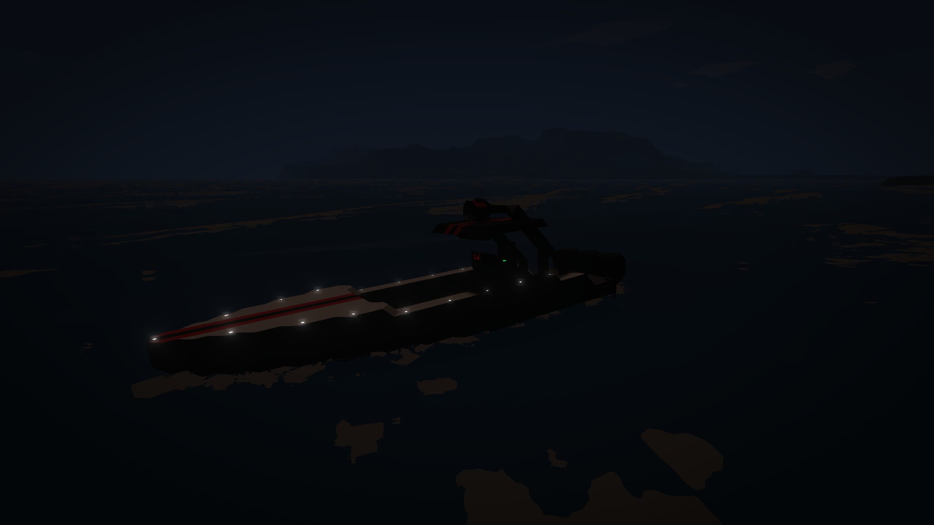
Thanks to the position of the small generator there’s never a shortage of battery power. So adding some running lights to outline the hull looked pretty cool. Also helps me to see it better on the ocean floor when it sinks ;-D.