Overview
This guide will describe basic and intermediate logic design concepts in an approachable format. It won’t cover more advanced topics, but it aims to give a workable understanding of logic design so you can apply these ideas to solving automation problems within Oxygen Not Included.
Binary Systems
Automation wires carry a binary signal. It only has two states, off and on. All sensors in oxygen not included also give their output as a binary signal. In-game, the sensor’s state can be seen to either be active or standby. Active (on) is green and standby (off) is red. Most people would associate active with 1 in binary and standby with 0, this is called active-high logic; however, active-low logic is also useful sometimes. Active-low connects active with a 0, and standby with a 1. All sensors in the game default to active-high configuration, but can be changed to active low in two ways. A) using a not gate (also called an inverter) will change the output, and B) changing the sensor’s activation setting to it’s opposite will accomplish the same task.
For example:
If you have a hydro sensor set to “above” 500g, then it will default to active-high and be active when its tile contains 500g or more liquid. It will be in standby (off) when it has less than 500g of liquid. So it’s a 1 if it’s more, and a 0 if it’s less. If you change the setting to “below”, the output is basically the opposite of what it would normally be. It will be a 1 if it’s less, and a 0 if it’s more. This would be considered “active-low” if the condition was really measuring whether it was full or not, though the terms themselves are pretty much irrelevant. The important thing is understanding which one you’re using. You can set it up so that it either A) Turn on when full, or B) Turn off when full. The confusing part is that “Turn off when full” means the same thing as “Turn on when not full”. So you might use this to control a pump that’s pumping into a chamber.
It’s also important to realize that sometimes things that seem the same aren’t. “Turn on when not full” does not mean the same as “Turn on when empty”.
Lastly, most devices in the game also follow active-high logic by default. So a pump will be turned on when it is supplied with an “active” green signal. Doors are active open and locked when passed a 0. A gas shutoff will shut off flow when passed a 1. In this way they actually feel more like an active-low, essentially gas flows when the input is low, and is blocked when the input is high. The power shutoff is the opposite, it passes power (enabling the circuit) when it is sent a 1, and breaks the circuit when sent a 0. If you’re unsure, a simple test will reveal the answer.
Diagramming and Planning
Creating diagrams, truth tables, and state machine flow charts can really help simplify the design process. It lets you tackle several small problems one at a time rather than just looking at an overly complex giant problem and scratching your head. Well go over each of these tools, and how they can help. State machines will be discussed seperately.
Diagramming is very useful. Each logic gate has its own symbol, and using a simple drawing may make it easier to see how things should/could be connected. Pen and paper is handy to use, but there are also websites you can use as well. [link] can be used for diagramming, but it can also be used for easy testing. There are lots of others, and also some free apps on the google play store. Making changes in these tools is much easier than doing it in game, so they can speed up design considerably.
Truth tables are almost fundamental. In fact, they should usually be the first thing you do when designing a new circuit. You should think “what do i need this circuit to do?”, “what are my inputs?”, “what are my outputs?”, and “What are the key combinations of inputs and outputs?” As part of this guide I will be creating a water purifier as a follow-along project, and we will likely refer back to our truth tables more than once.
Notation
Across the internet you can find many different circuit designs and such. In any conversation where people discuss logic you might see some things that may not make much sense at first. There are a few conventions, but as with anything no rules are absolute.
Outputs
The outputs of a circuit are usually denoted Q, X, or less frequently O.
Inputs
Inputs are usually denoted A, B, C, etc, but can really be whatever you like.
Operators
Often you will see a shorthand used to make it easier to write logic statements, these make use of “operators” which are symbolic representations of logic gates. The symbols chosen are chosen for a reason, and may make sense if you’ve studied boolean math and/or set math.
AND is related to multiplication (or intersection if you’re talking about sets), and is usually denoted by *, ^, or &.
OR is related to addition (or union in set terms) and is usually denoted by +, U, u, V, or v.
NOT is pure negation (with a not gate), and is usually denoted by -, !, or with a bar over the top of the thing being negated.
= is typically used to denote assignment.
Q=A*B
The output is given by combining A and B through an AND gate. It could be read as “Q is A AND B”
Q=A+!B or Q=A+-B
The output is given by combining A and the opposite of B through an OR gate. It could be read as “Q is A OR NOT B”
Logic Gates
Each logic circuit will be made up of groupings of logic gates designed to combine inputs in some way, and translate them to outputs. This allows us to create more complex behaviors by combining several simple behaviors. An example might be, “lock this door if there is too much liquid behind it, unless the override is enabled”. This would allow us to ensure safe use of the door, but provide a switch in case the unthinkable happens and our unfortunate dupe gets trapped inside. Then the switch will unlock the door regardless of the contents of the room behind it.
The basic gates included in the game are:
The filter and buffer gates aren’t true gates in the traditional sense, they are more like electronic components that perform similar functions. The buffer turns on immediately when the input goes high, but it doesn’t change its output to 0 immediately when the input goes to 0. The filter doesn’t turn on immediately when it’s input becomes 1, but it does go to 0 immediately.
Some uses for a buffer include: detecting when pulses are further apart than a specified interval, pulse extension, delayed cutoff, etc.
Some uses for a filter include: detecting when pulses are closer together than a specified interval, pulse shortening, edge detection, delayed action, etc.
Bear in mind that when using active-low logic (where red represents a logical 1), the buffer and filter essentially swap roles.
Logic Symbols
Inevitably you will encounter a problem you are struggling with and go to the internet in search of circuit design ideas. Most people will either post the actual math function or a diagram. The math function was covered in the previous section; here I will show some of the symbols.
You also may note that there is a unique math symbol for the xor functions that looks like a plus in a circle. Many people use that for easy notation. All the gates in this image are oriented with the input(s) on the left and the output on the right. Also notice that here outputs are denoted by the “x” symbol instead of a Q, but the meaning is the same.

Anywhere you see a small circle near an input or output it signifies an inverter placed there. So a NAND gate is simply an AND gate whose output is then passed to a NOT gate. There are also occasions where it’s necessary to invert one or more inputs. Gates where all inputs are inverted with not gates are commonly referred to as “bubbled gates”. So a bubbled AND gate would be represented by the function -A*-B.
Truth Tables
Truth tables will likely be a good starting point for you when trying to determine the needs of your circuit. All you do is map all your inputs and outputs on a table.
Here’s a simple example for an AND gate:
The gate’s output is only high/active when all inputs are active.
Here’s one for an OR gate:
XOR Gate:
Here’s a truth table for a sort of demux (demultiplexer):
The demux is the basis for most selector circuits for addressing and other things. It can also be used to create very complex state machines. The inputs are A and B, the outputs are W,X,Y, and Z. Only one output is active at any time.
Boolean Algebra
This section will largely be optional for most. You can accomplish everything you need without learning it; however, learning how the math works can help you to optimize your designs to use fewer gates. Using fewer gates means using less resources, but more importantly it means a simpler circuit which will be faster and more consistent in its operation. Simpler circuits also take less cpu time to simulate.
Check the final example for a great way to create multiple input AND gates easily.
Probably the single most important rule is how negation can be moved around.
if X=-A*-B, then X=-(A+B) or -X=A+B.
By looking at the truth table we can see that this is a NOR gate; however, the original function is written as a Bubbled AND gate. These two gates do exactly the same thing, but which one you choose might depend on your inputs and/or outputs.
So you can group some terms, invert each one, invert the group, and change the operation.
another example: if -X=(A*B) then X=-(A*B) and X=-A+-B.
This is the truth table for a NAND gate, but we can see that it’s the same as a bubbled-or.
Final example:
X = A*B = -(-(A*B)) = -(-A+-B)
(The reason the first step works is because A = -(-A), since two NOTS essentially cancel each other)
This is a standard AND gate; the interesting thing we can see is that the behavior of an AND gate can be created by only using OR gates and NOT gates. X=-(-A+-B)
The benefit of this may not be immediately apparent, but an OR gate is really just a simple junction with the inputs isolated from the outputs. Tie three or four lengths of automation wire together, and isolate the junction with not gates or buffers and you have a simple multi-input OR gate.
If you negate all inputs, and negate the output, then you have an AND gate! (and the isolation takes care of itself.
Below are two ten-input AND gates. The one on the left uses cascaded AND gates, and the one on the right uses a simple junction OR gate. The gate is the wire itself.
Both gates are active if all inputs are active.
Both gates are off if any input is off.


Timers, Edge Detectors, and Pulse Generators
The game has a “clock” item you can use for scheduling automation actions, but it is pretty limited. Each clock can only activate once per cycle, and both activation time and duration are set in percentages (which can be difficult to nail down precisely). Also, this may not be practical for jobs like load balancing a power system. If you don’t have enough power, you might try turning power on and off at intervals to different circuits, giving each some time. For this task a more controlled approach might be required. Clocks are also very useful in other circuits and for synchronization as well.
The best design I’ve been able to come up with for oxygen not included is to tie a buffer gate, to a filter gate, to a not gate, in a circular manner.

The direction isn’t extremely important, you can go buffer>filter>not, or filter>buffer>not. Either way works. The only difference between them is that the pulsed output for buffer>filter>not is active-low (gives a very short “off” pulse), and the filter>buffer>not is active-high (gives a very short “on” pulse) There are two important things to note: The main clock outputs can be pulled from either side of the not gate, but the space between the buffer and filter acts like a pulse generator. Secondly, the total wavelength of the signal is going to be the sum of both settings. So a 1 second filter and a 1 second buffer will give a two-second cycle. It will be active for one second and off for one second. If you set one at 3 seconds and one at 1 second, then your signal will repeat every 4 seconds. You can pull from either side of the NOT gate, one side will be on for 3 seconds and off for 1, while the other will be the opposite.
These can also be useful for duty-cycles. 50% on and 50% off, 25%/75%, and any others.
I was unable to obtain a reliable result for anything less than 2 seconds in terms of total wavelength. They may align with game-time or they may not. If all you need is a simple pulse generator, a buffer or filter with its output tied to its input through a not gate will suffice as long as the pulse duration doesn’t need to be extremely short.
This is a decent edge detector. It can be used as a pulse generator if supplied with a clock signal.

Another benefit of this design is that it triggers on both the rising and falling edge. Which is to say that it triggers its output whenever the clock signal changes from 0 to 1, and then again when it changes back to 0. So using my simple 2-second clock above, this edge detector sends a short pulse every second.
In order to use it to detect a specific edge, you need to AND its output with the clock signal (for rising edge detection) or with the inverted clock signal (for falling edge detection). This ensures its only gets triggered once per cycle of your signal.

Finite State Machines: A Water Purifier
Finite State Machines are a pretty general concept, but basically it all amounts to this:
A finite state machine is defined by its states and transitions.
It has a finite and countable number of states, and each is well defined.
Each transition connects one or more states.
The machine can only occupy one state at a time.
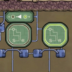
Usually a state is stored in a latch or register. Since the game includes RS Latches, that will usually be what you’ll use in-game for storing the state.
We have a germy polluted water reservoir with a pump, and that pumps into our tank.
Our tank has a pump that pumps sanitized water to our water seive.
Lets start by identifying our process, we want three discreet stages:
First, we want to pump germy water into our tank until it’s full. We’ll call this the Filling state.
Second, we want to heat the water until there are no germs left. We’ll call this the Heating state.
Third, we want to pump the water out until it’s empty. We’ll call this the Emptying state.
This lets us know that we need three sensors at a minimum.
So now lets describe our system so far:
We’ll have a full sensor, an empty sensor, and a germ sensor as our inputs.
The outputs will be the pumps and the heater.
We could skip the heater as an output, but it could damage itself when liquid levels are low; so we’ll turn it off to save power and so we don’t have to keep repairing it.
So the the germ sensor tells us to transition to the emptying state, the empty sensor tells us to transition to the filling state, and the full sensor tells us to transition to the heating state.

RS Latches work well for this task, since our state machine only needs to transition in one direction.
Here’s a link to the circuit diagram. It’s interactive so you can see how the parts work. Each sensor has been replaced by a button. You’ll click run, then click each button to simulate that sensor being tripped.
[link]
And here is the final product.

You could run the heater and filling pump off the same state, thus decreasing the machine to two states; however, the machine wouldn’t be as versatile as it is now. If you use the germ sensor to trigger the transition, the water could begin emptying before the tank is full. If you use the full sensor to trigger the transition, the system could pump germy water out. One is less problematic than the other.
Applied Automation Design
In the previous section we came up with a design for a water purifying setup. However, you might have noticed that we only needed three states, which can be handled with only two bits, however, our design uses a three-bit state machine.
Our current design has three bits and three states:
001 is “heating”
010 is “emptying”
100 is “filling+heating”
This could be “simplified” to 00=heating, 01=emptying, 10=fill+heat.
so if B is 0, then the heater should run.
if A is 1, and B is 0 the tank should fill.
and if A is 0, and B is 1, the tank should empty.
We can guess that since the heater requires a 1 to be active, we might want to change this around a bit so we can eliminate an extra gate. Let’s just negate everything – 11=heat, 10=empty, 01=fill+heat.
Now if B is 1, the heater should run.
The next question is “How do we decide when to set and reset the latches?”.
At the moment we have an empty sensor, a germ sensor, and a full sensor.
Referring back to our state diagram, it should still hold true, regardless of how we represent our state.
if the empty sensor triggers, it should transition to filling. So it will reset latch A and set latch B.
the full sensor will set latch A and latch B (although it’s not strictly necessary to set latch B since our state machine only has one-way transitions, it’s always good practice to do this)
the germ-free sensor will set latch A, and reset latch B (same applies here, but with latch A this time)
The end result is one less RS latch, but two additional AND gates (for the outputs of the latches). So in this case, the only reason to simplify would be if RS latches were particularly expensive. However, on a more complex circuit (3 bits can handle up to 8 states) the space and material savings could be very noticeable.
New Additions
Here’s an 8-bit multiplexer:

Red – control clock
Blue – Input switches (could be sensors or whatever else)
Yellow – multiplexer (mux)
Purple – de-multiplexer (demux)
Green – outputs, I used lights (but again, can be whatever else)
So, onto the pieces. The control clock:

If you look at all three of the clocks bits as being the least significant bit (on the left) to the most significant bit on the right… it basically counts from 000 to 111 (from 0 to 7).
I won’t talk much about the inputs and outputs, they’re each pretty self-explanatory. I use the new 4-wire buses to simplify and keep the wires tidy… but it’s no different than literally running 8 individual wires.
For the mux:

For the demux:

The end result:
I’ve encoded the binary byte 10001011 using switches. This byte is transmitted serially on the 4th wire down to the lights. All eight bits are able to fit on a single wire thanks to multiplexing. You can use these in other ways as well, and they also have some logic applications (especially for encoders/decoders) because they function like cascaded AND gates. Using the muxes as an example, if the top data bit is green, and the other data bits are red, the selector acts like a NAND gate combining the two switch bits, the output is on only if both inputs are off. The middle two data bits change the behavior to basically be S1^!S2 or !S1^S2, depending on which data bit is active. If the final data bit is high, the selector acts like a regular old AND gate. So you could use this to craft some pretty complex situational logic. Another example, if the second and fourth data bits are green, then the output is just S1, regardless of what S2 is. There are other ways of combining the data and switch bits to get different behaviors, and the same goes for the demuxes as well.