
Overview
A guide to the basics (and some more advanced stuff) when you start building a sub, some stuff I wish I knew and some stuff I have learned.
Basic Controls
Here is a list of controls to use in the sub editor.
Arrow keys = Move item by pixels up or down
Ctrl n/m = Flip item on the axis
Ctrl c/v = Copy and paste items (can be done between save files)
Right click = Will open up a context menu with copy, paste, and delete
Space + Left Click = Link hull (on border edge)
Space + Right Click = Unlink hull (on border edge)
Power and You!
These are the Wiring basics for powering your Sub.
Start with wiring (connecting) the ‘power out’ node from the Reactor to the ‘power’ node in a Junction Box. Connect the output from the Reactor to 1 Junction Box only.
Why?: Reactor Output does NOT split across the number of wires.
Power (Output) from the Reactor flows in parallel, meaning each wire (output) from the Reactor will have the same amount of power (Output) flowing through it.
For example, if the Reactor’s output is 3000 and there are 2 wires connected to the Output, the power grid will receive 6000 output (3000+3000). This typically leads to Overvoltage, where the Junction Boxes are rapidly damaged and/or burst into flames.
⦁ The Reactor is the power generator of the game. It generates heat from Fuel Rods, then converts that heat to power.
⦁ If the Reactor is producing less power (Output) than the power grid needs (Load), Items connected to the grid will not function, due to Undervoltage. If you try to operate an Item, you will see a prompt: “Insufficient Power”.
⦁ If the Reactor is producing more power (Output) than the power grid needs (Load), it will Overheat. If the Reactor overheats for too long, it will ‘Meltdown’ (explode).
⦁ Junction Boxes are the main power conduit in the Sub’s Power Grid. They have 1 power node and 4 signal nodes that wires can connect to. Each node has a max capacity of 5 (wire) connections.
Note: Power flows in BOTH directions through a Junction Box.
You can then wire (connect) Items (e.g. Engine, Oxygen Generator, Pumps) to that Junction Box, or additional Junction Boxes, to increase the capacity of the Power Grid you are making.


Unlike Junction Boxes, Batteries have a separate ‘Power In’ and ‘Power Out’, so power only flows in 1 direction. Batteries should be wired (connected) from a Junction Box and to a Junction Box. They also have an adjustable ‘Recharge Rate’. The easiest way to manage the battery is to use a toggle on the on/off of two relays, allowing to disable charging well the battery is needed to prevent backflow waste into charging the battery.
Multiple Batteries can be used to reduce or prevent Power Fluctuations in the Power Grid, which cause Reactor Overheating (overvoltage) and Item failure (undervoltage). The main causes of Power (Load) fluctuations is Items with high Power (Load) requirements, like the Engine, Fabricators and Large Pumps.
For example, in one of my ships, The Velox, 1 Battery is wired (connected) to the Deconstructor and Fabricator. There is also 1 Battery for all the Large Ballast Pumps, one for the all the Lights, and one for the Navigation (Nav) Terminal and Engine. So if the Reactor runs out of fuel, all the devices will still have Power for a short while, which can mean the difference between life and death.

Clean up your Wires!
Whenever you wire 2 items together, the wire forms a direct path between the connected items. This is very helpful for keeping track of what is connect to what, especially if you need to make changes to your wiring.
However, once you are done with powering the guns and Fabricators, or setting up the signal pathways for your remotely controlled drone, all that wiring can become a jumbled mess. You do not want to leave it like this, because it does not look good and it affects game play.
To create a node select a wire you wish to bend and hover over a section over it,hold control and click on a part of the wire.


Note: Node movement follows a grid.


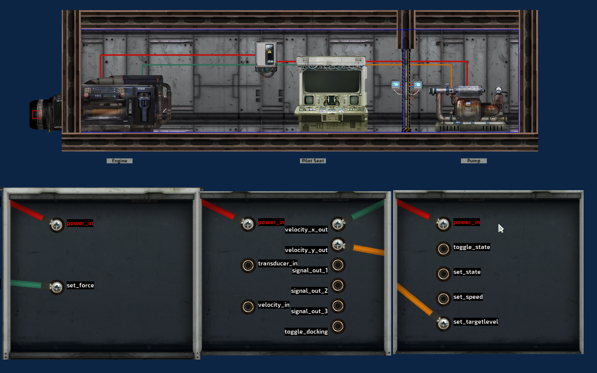
Driving your sub.
To get your sub moving, you need wire a few items together:
⦁ Navigation (Nav) Terminal – Allows you to tell the sub where you want it to go
⦁ Engine – Responsible for X axis or horizontal (forward/backward) movement
⦁ Ballast Pumps – Responsible for Y axis or vertical (up/down) movement. Ballast Pumps are Pumps that require some additional setup.
Note: To setup up a ballast pump, simply add “ballast” to the Tags located in the pump’s properties. When you are done, the tags should look like “pump,ballast”
First, make sure all items are powered (their power nodes are wired) and pumps are turned on.
(To turn on a pump in the Sub Editor, go into Character Mode, select the pump and drag the ON/OFF lever to the ON position).
Then, wire the engine’s set force node to the nav terminal’s velocity X out node (the green wire in the example below).
Lastly, wire the pump’s set target lvl node to the nav terminal’s velocity Y out node (the yellow wire in the example below).
NOTE: Every engine and ballast pump needs to be wired to receive a signal from the nav terminal in order to work.
Ballast room basics.
To give your sub Y axis or vertical (up/down) movement your sub needs Ballasts. Ballasts control the sub’s buoyancy by taking in or letting out water, to make the sub lighter or heavier.
The amount of water in the sub determines if (and how fast) the sub goes up or down. If the sub’s ballast is too small, you will not be able descend (go down) quickly. If the ballast is too big, you won’t be able to ascend (go up) quickly.
The game calculates ballast via the Optimum Neutral Ballast Level. To see what your optimum neutral ballast level is, select ALL ballast hulls (to select multiple items, Left Click on one, hold CNTRL and Left Click on the others), then look at the top left corner of the sub editor to find the optimum neutral ballast level.
This value needs to be entered into the Nav Terminal’s corresponding field (found in the nav terminal’s properties) for stability when set to “Maintain Position”.
NOTE: You Optimum Neutral Buoyancy Level should be between 0.3 and 0.5

To setup a ballast you need a ballast pump and a defined ballast hull(s). This hull should be surrounded by walls (but have entry access to the ballast space). For the purposes of this guide, we will call this a Ballast Tank.
Hulls are rectangular, so if you want to build angular ballast tanks, multiple hulls are needed to fit the desired shape. These are called multi-hulled ballast tanks.
There are some rules involved with building multi-hulled ballast tanks.

The ballast pump only accounts for the single hull it is in so it needs to be located in the lowest hull but also the tallest hull.
These two examples will work:
But these two will not,

In the top bad example, the pump will only fill up to the top of the hull it is in (the hull to the right), leaving the two other hulls partially filled. In the bottom bad example, water will fill the two hulls to the left, but will not fully drain them.

The ballast pump will ONLY fill the designated ballast hull with water. In other words, if the top of the ballast tank is open, it will not overflow, unless tampered with. This makes platform walkways over ballast tanks possible.

Dealing with all this water.
On your submarine you have multiple methods to drain out water when that breach finally gets repaired. The tools you can use to do this is with pumps and ducts. (and hatches)
With the pumps the large pump is more efficient then the small pump power wise (unless you alter it), the amount of small pumps to equal the flow rate of the large pump uses 60 more watts but the small pumps are more compact so allow for easier placement.

Next in line is the passive duct, when it receives a signal it will open allowing water to flow through. This can also be accomplished with hatches for a faster drain rate to the room below. For these to work they need their gaps to between rooms, and ducts can be placed on walls as well as floors.
The signal required to activate the pumps and ducts is through a water detector, or can be done manually, but water detector is the best bet. When placing the water detector you should place it on the bottom of the hull it is in not on the floor of said room, not placing correctly will cause the room to keep any water below said water detector.

In this example the left water detector will not drain that last little bit of water well on the right you will have an empty hull. With wiring of the water detector, for both you want them on set state so when it senses water it opens the ducts like a door or turns on a pump.
Some methods to drain a sub are:
- Using ducts and hatches to drain to the ballast tanks.
- Pro- This requires no extra power then what is already being used in the ballast tank.
- Con- With this is if you are going down the sub will not drain since the ballast tank will be full of water.
- Con- If water is sensed and you have breaches this will hasten your flooding since rooms will start opening up to already flooded rooms.
- Using a mixture of smalls and ducts with the pumps being on the lowest deck above the ballast.
- Pro- Uses a small amount of power but can quicken the process of draining the sub.
- Pro- Independent of the ballast so will work constantly till the sub is empty.
- Con- Will use a bit of power and add strain to the grid.
- Con- Will still open up rooms to accidental flooding from the ducts.
- Using only small pumps in every room.
- Pro- Good to keep vital areas of the sub dry in the worst conditions because items in water long term will start breaking down.
- Pro- Fastest method to drain a fully flooded sub.
- Con- Will put massive strain on a subs power when fully flooded.
- Con- Can drain back up power quickly when you are trying to get unflooded.
Hulls, gaps and how to link them.
Hulls
Every room on your submarine needs Hull pieces, which allow you as the player a dry space to breathe and walk. The hull piece is represented by a blue rectangle. When placing a Hull piece, its edge should be inside walls, shells, ducts, doors or hatches, and must touch (but not overlap) the edge of other hull pieces.
NOTE: Ducts are non-powered vents that allow downward drainage of water, but water can pass through them in BOTH directions when open.
Gaps
For hull pieces that are touching, but are not inside walls, shells, ducts, doors or hatches, Gaps need to be manually placed, otherwise water will not be able to flow into or out of that section of the hull piece. Gaps tell the game how water flows into/out of the hull. The arrows on the gaps determine which direction(s) water will flow through that gap. Open gaps are blue, while closed ones are red.
NOTE: Doors, hatches and ducts automatically generate a Gap.
When placing Gaps for multi-hulled rooms, every part of the hull pieces that touch (but is not inside a shell, wall, duct, hatch or door) requires a separate gap

Using one long gap will cause water to move between the hulls improperly.
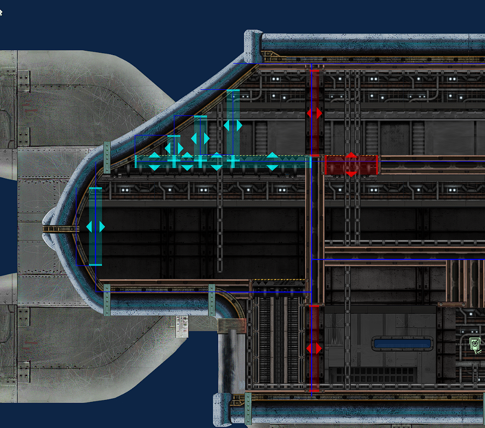
You need to place them with the side of the smaller Hull being the max size of the Gap.

Linking Hulls
The hulls of a multi-hulled room should also be linked together. When hulls are linked, they are displayed as one group in the Status Monitor. Linking is done by selecting a hull, holding SPACE and Left Clicking another hull. Right Clicking will remove the link.
NOTE: Only hulls that touch each other should be linked.

Here is an example of a fully hulled, gapped and linked sub.
You can get this sub in the Workshop: [link]

Pressure, Hulls and Gaps
Outside the sub has a pressure that will crush your character if you are not wearing a diving suit. When a breach occurs, this pressure also appears inside the breached hull. For the purposes of this tutorial we will call this pressure Overpressure.
Overpressure is a percentage above the hull size of 5%. So if a hull is breached and fully pressurized the total volume in the breached hull will be (hull volume+5%).
If you have a room with a volume of 50,000, if breached and fully pressured, the total volume will be 52,500 (50,000+2,500).
Setting up your guns.
Wiring Rail and Coilguns are easy to do. Connect a supercapacitor’s ‘power in’ node to a junction box’s ‘power’ node, and the ‘power out’ node to the ‘power in’ of the coil/railgun. Connect the periscope’s ‘position out’ and ‘trigger out’ nodes to the ‘position in’ and ‘trigger in’ nodes on the gun. Lastly, you need to link the ammo loader to the gun. Click the loader then hold SPACE and click the gun to link them.

More on linking.
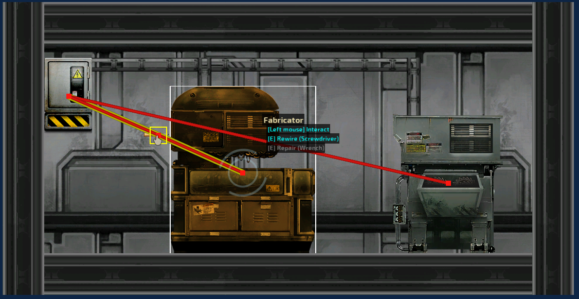
You can also link Storage Cabinets to Deconstructors so that its output is automatically stored, and Fabricators so it will automatically pull the required materials from the liked storage to craft items.
When an item is linked you will see a green line between them.
If you tick ‘display side by side’ in the properties of one or both linked items, the link indicator (green line) will turn purple, and the User Interface (UI) will be displayed together.
NOTE: the nav terminal and status display UI showing together is done in this manner.
There might still be a glitch for fabricators and deconstructors, the side by side display ends up breaking after a while (see the right side of the below example), but this may be fixed in the this current build. (WILL TEST)

Relay Power.
Junction boxes only have 1 power node, and you can only connect a maximum of 5 wires to a node. This limits how many devices can be connected to a junction box, resulting in a lot of junction boxes if you have a lot of items that require power. The main item that this happens with is lamps, when you are wiring the lighting for your sub.
For example: If you have 20 lamps to power, you will need 5 junction boxes just for the lamps alone! (1 connection for power to the junction box, and 4 connections going to the lamps).
In order to reduce the number of junction boxes, you can use a Relay. Wiring the relay to a junction box, then the lamps to the relay, will allow you to only use one slot in the Junction box for five lights or other items!
Unlike a junction box, relays have separate input and output nodes (for both power and signal). This allows more total connections than a junction box, and control over the flow of power/signal, because power/signals only flow through the relay in 1 direction.
NOTE: The relay is turned off by default. If the relay is off it will NOT allow power or signals through it. Make sure to tick “Is On” in its properties, unless you specifically want it off.
The relay has a maximum power of 1000 by default. If you are connecting items that require a total power of more than 1000, you will need to adjust this value in the relay’s properties, otherwise, overvoltage will occur and the relay will deteriorate.

For example, you can connect a deconstructor and a fabricator to a relay and only use 1 junction box slot. The deconstructor and fabricator each use 500 power, totalling 1000. Another example is 2 large (ballast) pumps, totalling 600 power, and 3 regular (bilge) pumps which use 180 power, totalling 780 power.
Lastly, when wiring POWER, do not daisy chain relays for anything but lamps (junction box to relay to relay). Daisy chaining relays for SIGNALS is fine.

Whats the Wifi?
The Wi-Fi component is a wireless SIGNAL carrier (it does not carry POWER). It uses channels that can be edited in the wi-fi component’s properties to transmit/receive signals, and has a maximum range indicated by a circle (when the component is selected) surrounding the component when in the Sub Editor.
You need 2 wi-fi components (a signal pair) for the system to work; 1 component to transmit a signal, and 1 to receive a signal. To setup a component to transmit, connect the signal wire to the ‘signal in’ node. To setup a component to receive, connect the signal wire to the ‘signal out’ node.
Example: You can wire the aiming and trigger signals from a periscope to a coil gun via wi-fi, with each signal on a separate component and channel.
Each signal pair needs to have their own individual matching channel, so there is no overlapping of signals. In the example below, the engines are on 21, pumps 22, transducer 23, and docking is 24.
NOTE: Components can both transmit and receive at the same time.

Drone Setup.
The drone’s ballast pumps, engines and docking toggle need to receive a signal from the nav console on the Main Sub.
The transducer transmits a signal to the nav console in the main sub.
The nav console on the main sub that controls the drone must have the “use transducer” in the properties ticked. If it isn’t, the sonar will stay centered on the main sub.
NOTE: Make sure to supply power to the drone’s nav terminal.

IDs and Security
Each character on your submarine spawns with and ID card. This feature allows the sub to have access restrictions. For example, the Armory can only be accessed by someone with a Captain or Security ID card. This can also be used on certain storage devices.
In the example below, the door to the left can be opened by anyone, with or without an ID card. The middle door requires an ID card to be opened. The door to the right requires an ID card tagged with id_captain to open.
To create that ID card, enter id_captain (no apostrophes) into the ID card tag of the Spawn Point. Enter the same id_captain into the door, hatch or secure cabinet’s ‘picked required’ field, that you want restricted access to.
If you change the Assigned Job in the spawn point to ‘Captain’, it will make sure only the Captain gets the id_captain tag on their ID card.
Each spawn point can have its own unique ID card tag, which when properly configured, can deny access to sections of subs to certain job types, which can be useful in thwarting traitors.

NOTE: Automatically opening doors bypass ID card restrictions, as motion sensors only detect movement and human/non human.

Finding your Waypoints
With way points there is 2 states and 3 sizes, the two states are blue and green (I couldnt get them to turn green in this picture, but that’s beside the point), blue is for outside the sub denoting that the AI need a diving suit to be at this waypoints, green are internal.

Now on to size, the smallest or number 1 way point is for general movement and can be placed anywhere, the number 2 way point is for if either there is a door or a ladder involved, and finally the number 3 way point is for when both a ladder and hatch are involved. Also it is good practice to place the 2 and 3 way point’s directly on doors and ladders, this lessens the AI from messing up.
If when place your way points and they are not properly sized clicking on them once or twice will size them to the correct one in relation to the situation. If you plan to do the way point placement manually you can link way points to each other to create paths by click the first way point and then holding space and clicking the way point you wish to connect to. Finally generate way points at the end of your build should properly work but its best to quickly review any doors and ladders to make sure they have them properly lined up and sized.
Also if generate way points is clicked it will erase all way points and insert new ones, so plan to be doing way points as you final step.