
Overview
This tutorial presents the modelling and texturing process of car model making in the way I model my cars. Aimed for people who have some skills with Autodesk 3ds Max modelling software.
Intro
This tutorial is a step-by-step guide or presentation of how I make my cars
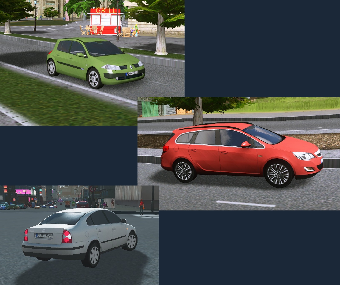
Here are some examples of already made cars which can be found in Steam Workshop:
These cars are modelled using:
Autodesk 3DS Max 2012
-with-
VRay renderer (used for Ambient Occlusion rendering)
NOTE: You can use later versions of 3DS Max, UI is practically the same.
I have set personally appropriate triangle counts for my cars:
Main model: ~2500 (< 3000)
LOD model <100
I make my cars using high-poly models as a base.
If you are going to make a car using this tutorial, it doesn‘t mean you should follow these tri count rules. Choose it as you wish. Some prefer ~500 tris, and some are okay with several thousand tris.
Preparations
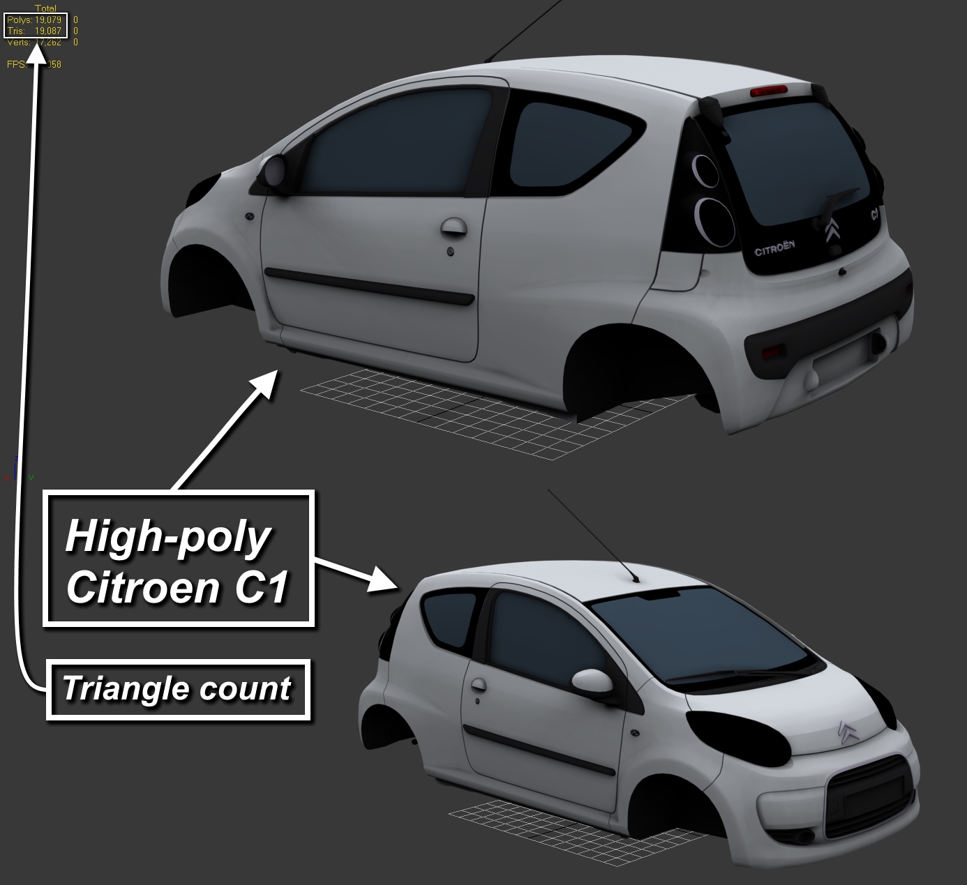
To begin modelling, we need to find a good high-poly model. By good, I mean it shouldn‘t have various mesh faults and should be textured.
You can find high-poly model collection I use in the end notes.
For this tutorial I will use Citroen C1. You can see it has 19k triangles.
Now, when we have high-poly model in our scene. We should modify it, in order to properly build low-poly model (for Cities: Skylines).
We need to make our high-poly model as one object.
Do this by selecting any model part and then, using Attach or Attach List commands, attach all objects to one.
I recommend you to use Attach List option, then select all model parts and, finally, attach everything to one.
When you think you are done, try to hide your model by clicking right mouse button (RMB) and then clicking Hide Selected. If you see any parts left, you need to get back and attach those also. To unhide model click Unhide All.
If your model was one object already — you are lucky!

Once you made high-poly model as one object, time to move on modelling low-poly model.
We begin by creating a simple box of any size somewhere nearby high-poly model:
1. Click on Create
2. Click on Standard Primitives
3. Click on Box

Draw it in Top View:

After that, convert this box to Editable Poly.
1. Click on Modify tab.
2. Right click on the Box (in modifier list window)
3. Click Editable Poly

Moving on.. We are going to set our high-poly model as a base of our upcoming low-poly model.
Make sure your box (as editable poly) is selected.
1. Double click on Freeform
2. Click on small downwards Arrow in the right of the Grid.
3. Click on Draw On: Surface
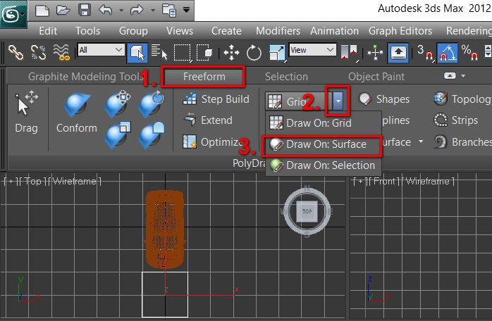
NOTE: If you cant find Freeform, click on Graphite Modelling Tools in the toolbar:

4. Click on Pick
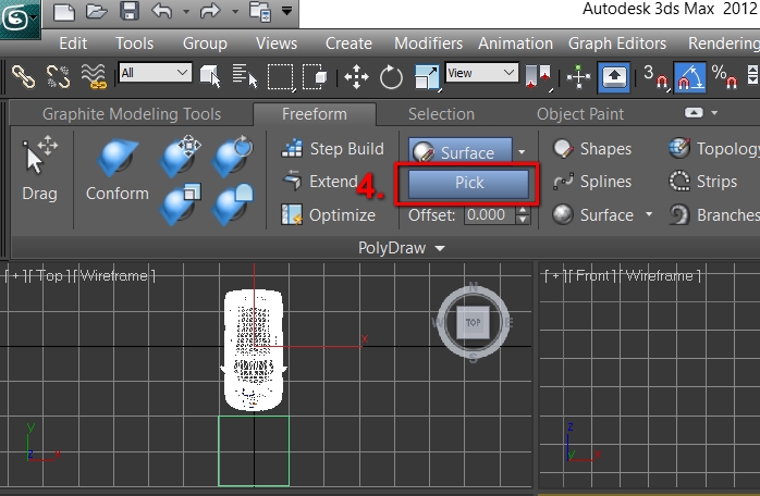
Then click on the high-poly model. After you do this it will look like that:

Few more things before making the mesh model:
For easier modelling using high-poly as a base (surface) it is recommended to enable Edged Faces option in Perspective view.
5. Click on Shaded (it also can be Realistic, Consistent Colors, etc.)
6. Click on Edged Faces

Mesh Modelling
Now we can finally start modelling the mesh. We will do this by placing vertices one by one. Yes, one by one, and you will have to manually place hundreds of it. So make yourself ready, adding vertices is just a simple mouse click while adjusting vertices or creating polys out of them requires 1 to 3 keyboard keys + mouse click.
Let‘s begin. Click on Step Build
(Mouse over it to see all controls of the step-building)
This list explains it clearly, but I will also give short summary

Shift (only) – is only useful when there aren‘t many vertices placed. It creates a poly from closest four points, so when there will be lots of vertices, this option won‘t work well, it will create weird shape polys, not as we want it to.
Ctrl + Shift – most used key combination. By holding those keys, you need to click on four vertices, after clicking 4th vertex – polygon will be created.
Shift + Alt – often used key combination. By holding those keys, you need to mouse over the three vertices, after having moused over 3rd vertex – mouse click (LMB) and the triangle will be created.
Ctrl + Shift +Alt – also often used key combination. By holding those keys you can freely move the vertex on the surface (high-poly).
Alt (only) – remove a vertex.
Ctrl (only) – rarely used. It removes polygon. If you create a poly wrong in the modelling process you can just use Ctrl + Z (undo) to remove it and try again. Ctrl is mainly used when later you accidentally find some polys wrongly created. But even then you can use standard Polygon Selection tool, click on it (highlights in red color) and delete.
Let‘s place first vertices. Edged Faces option is used to see the high-poly geometry for easier vertex placing. So place it in the way you feel like the model will look OK (will look OK in Cities: Skylines).
NOTE: Since cars are symmetrical, you must model only one side of it, the other one will be mirrored.
Here is a picture preview:
Hold Shift and click in the middle of the 4 vertices.
Now you have made first polygon!


Now it‘s time to get rid of that box. 😉 That was useless, you think? Well, you can‘t start step-building out of nothing, there should be any kind of mesh already created. There also was a way to make e.g. a Plane and place it on the roof, so no deleting will be required. But then it is needed to adjust its location, size, etc. Creating a box is more simple.
To do this, first deselect Step Build and then select Element in Selection tab which is in Modify tab. And then click on the box.
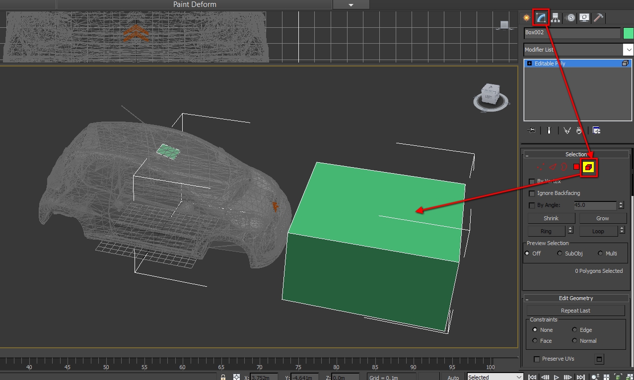
Whole box should be red now. Now press Delete and it‘s gone, we don‘t need it anymore.

1. Select and keep selected Vertex selection tool , it will help with Shift+Alt combination (vertices will become red after mousing over):

Click on Step Build again and continue adding vertices.
After you placed few more, use previously mentioned combinations and create new polygons.
In my case I made 4 new vertices, and used Shift (only) combination to make new polygons (2 new).
New polygons:


Now you know how to place verts and create polys.So try to continue making a car mesh on your own, good luck!
Work in progress state of making a mesh looks like:

To avoid white edges at far zoom levels, you need to separate colored parts from non-colored parts by modelling polys for each own, separated by edges of course.

Once you modelled the body, you need to make simple wheels (if you haven‘t made it already).
Wheels are created using Cylinder tool. You can find it in:
Create -> Standard Primitives -> Cylinder
Now draw any size cylinder (somewhat close to real size of the wheels) in the Left or Right viewport.
In the Cylinder settings set Height Segments and Cap Segments both to 1. And Sides – 16 (my most prefered amount of sides for wheels, also you can set it lower but it is best to have it as iterative of 4: 8,12,16,20…).
Finally, adjust Radius and Height parameters and move cylinder in correct position. You should have something like this:

Now if you have fully made and are happy with one side of the body it‘s time to mirror it, but before that, there is a very important step!
Since we placed vertices manually by hand, so those won‘t be in exact position by accuracy of 0.01 cm and more. So every vertex that is meant to be in symetry line should be in absolute zero of the X axis.
We will use Top viewport (front or back is also acceptable) Click on Vertex selecion tool and open Move Transform Type-In window by right clicking on the Move tool.


You will need to select every single vertex on symmetry line (X axis) and set its position to 0.
Don‘t get fooled if it says 0.0m, it just can be e.g. 0.0004m, Max just rounds it. It is a must to type 0 for every vertex.
Next on the list is mirroring the half of the body we currently have. Before this, Attach the wheels to the main body (in the same way as we did in model preparations steps with high-poly model) if those are separate objects.
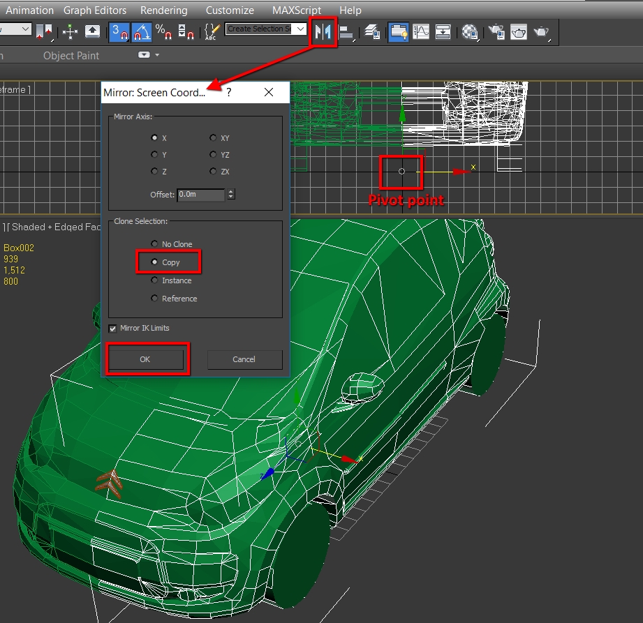
Make sure pivot point is on X axis (0.0 m) then click on Mirror and choose Copy in Clone Selection.
Now select back the part we were making and Attach the mirrored one.
Now select all vertices that are in the symmetry line.
Click on Weld. Notice the amount of vertices before and after welding. Typically it should halve by half (e.g. 200 -> 100), or even more (200 -> 80, — that would happen if there were duplicated vertices). If it halved by less than half (e.g. 200 -> 140), recheck your model, it means some vertices were not precisely on symmetry line, or there is somekind of problem of some particular vertices.

Congrats! Mesh is now complete.
Smoothing
As you can see model can‘t be released in such condition, it
has no smoothing and is very edgy.
So now prepare to work with smoothing groups. I will cover only the basics, you will have to search for more
in-depth guides about smoothing groups if you have no experience in this.
.

Most basic smoothing is selecting the polygons you want and clicking Auto Smooth. A number value on the right is the threshold angle of two connected polygons (that can be smoothed) separated by edge. For exampe if threshold angle is 45°, polys that are connected by less than 135° (180-45) will not be auto-smoothed, edge (facet) will remain. If you want this edge to be smooth increase the threshold.
Also you can manually choose any of the Smoothing Groups from the list (from 1 to 32). Angle is irrelevant here.
I recommend manually assigning Smoothing Groups (one for the windows, one for the lights, one for the wheels, one for the side body, one for the rear and etc.) so it will be a lot easier to select polygons for UV wraping.

Polygons can also have multiple Smoothing Groups (it is shown in the video also). Here is my example:
For half of the bonnet I applied group no. 2

For another half I applied group no. 3

Here you can clearly see the edge separating both sides

Let‘s select polygons that have that egde, and apply both 2nd and 3rd smoothing groups:

End result, middle (non-smooth) edge is gone:

Here the smoothing tutorial ends. You have learned everything that is needed to fully smooth the car so that it will look similar to how it looks like in real life.
After you are done with smoothing, prepare for not that easy task: UV mapping (wrapping), I, again, will cover only the basics.
UV Mapping
UV mapping is all about how geometry of the 3D model lie on 2D texture. I will cover basic UV mapping tools and techniques, so it will depend only on you how you arrange your UV map.
IMPORTANT NOTE! – If you plan to render Ambient Occlusion (AO) effect for your car, DO NOT place UV seams on top of other seams (overlap) in UV map. You can overlap only those seams that are not going to have AO at all, or to have identical AO. I will explain it next while giving examples, so if you are not planning to render AO, skip it (not recommended).
Here we have two seamed elements of the hood. These parts should have separate space on UV map (different AO)

This is an example of how seams shouldn‘t be placed:


In the next case I overlap these seams, because AO for all of them will be the same. (Wheels):

I will use car mirror as example in further UV mapping guides.
To begin with, we need to open UV editor. Do this by selecting Unwrap UVW from Modifier list, before that select some amount of polys (highlighted in red color).
In the UV Editor window, select Polygon tool (red square), which is found in lower left corner.

Flatten Mapping — found in Mapping -> Flatten Mapping... This option flattens 3D area to 2D by maximum threshold angle. Similar way as Auto-Smooth works (it was explained previously). Spacing is all about how far seams will be placed from each other in the UV map. Leave 3 ticks ticked except Rotate Clusters.
4 buttons above the big red arrow are advanced flattening tools, try those out by yourself.
This tool is super effective for UV mapping flat shapes, but isn‘t for curvy and rounded shapes. You need to use other tools or select lesser amount of polys manually.

Normal Mapping — found in Mapping -> Normal Mapping... This option forms UV seams planary by chosen perspective. Useful for flat surfaces but also for rounded surfaces, with manually selected poly amount. There in the list you can find normal perspectives, choose the one you think is needed.

Unfold Mapping — found in Mapping -> Unfold Mapping... This option just literally unfolds polys to a flat 2D surface. Let‘s say we have a cylinder-like object with 8 rectangular sides. When unfolded we will have one big rectangle, divided into 8 same sized parts. So that‘s how this UV mapping option works, it works best for single row polygonal connection UV mapping, and it is absolutely useless for multi-polygonal mesh UV maping. Check the pic:
Useless for:

Best for:

One polygon should connect with maximum two other polygons, otherwise you‘ll get result like in previous picture (first pic for Unfold Mapping).
Packing UVs — This is used to pack UVs into UV map window (checkered) in correct size. Also you can use Tools -> Pack UVs.…
After you finished working in UV editor, close it, then right click on Unwrap UVW (highlighted blue, in the Modifier window), then click on Collapse To or Colapse All. After that select new polygons and repeat same procedures. For more info about UV mapping, look for dedicated tutorials.
Final UV map should look something like this:
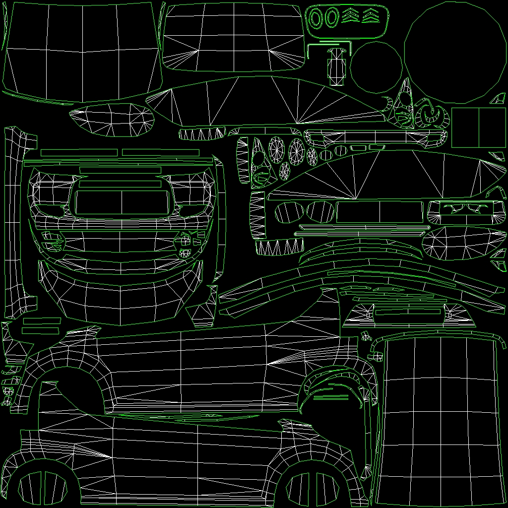
IMPORTANT NOTE! — Since we are modeling this car for Cities: Skylines, _c texture (colormask) is used to define which parts of the car are going to be colored and which are not. White — colored, black — not. So if in colormask there are cases when one pixel is white, then next one — black and then after few black pixels, again, next pixel is white. You are going to see white edges when zooming out in-game. To avoid it, arrange your seams in UV map in the way that to-be-colored seams should be on one side of the UV map, and uncolored seams on another. Try to do it like in my example:
Orange — Colored parts
Blue — Non-colored parts.

AO Rendering
I will cover two methods of AO rendering:
1) Using VRay renderer (3rd party software for 3ds Max, paid. You can use trial version or use illegal ) copy, it’s up to you)
2) Using built-in 3ds Max renderer (Default Scanline)
There is also built-in Mental Ray renderer, you could try to use that also.
Internet is full of guides how to setup renderers for AO rendering, so I will skip this in my tutorial, but I will provide the presets I use. You can download these from github:
VRay renderer preset[github.com]
Scanline renderer preset[github.com]
Up next — setup of the render materials by both methods, use only one!
C:Users…Documents3dsMaxrenderpresets
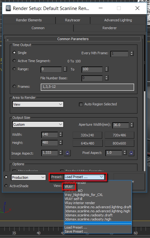
2. In 3ds Max press F10, there below is Presets list, choose VRAY, if there is no such, click on Load Preset.. And find it manually.
3. New window pops up. Click Load
If it didn‘t work, because of different and incompatible versions of 3Ds Max or VRay, you will need to manually find a guide how to setup renderer.
4. Now we need to setup a VRay material. Press M, this will open Material Editor. For compatibility with this tutorial, choose Material editor mode to Compact.
5. Choose any empty material. Click Standard. Expand the
V-Ray Adv list and choose VRayMtl, click OK.

6. Click on the square in the right of Diffuse; expand V-Ray Adv list and click on VRayDirt; click OK


You can „play“ with these settings, set radius to any you want, subdivs can be 32 or higher. More means better quality and longer rendering times.
8. Once you are done with settings, apply this material to the car model. Do this by dragging the ball on the car, or clicking
Assign Material to Selection (third button under Material balls, before red X); just make sure your car model is selected.
9. Create a simple base under the car (to simulate fake ground effect). Create a Plane in this case: Create -> Standard Primitives -> Plane

10. Apply same VRay material to the Plane too.
11. Select the car model. Just make sure high-poly model is hidden. Only our low-poly car model and plane should be in the scene.
12. Press 0 (zero).
13. Set UV channel to 1. In the Output tab, under the table click on Add..; Click on VRayGlobalIllumination, and then Add Elements. Also check if other settings (not mentioned) match yours.


14. Click on square with …
choose texture saving location and type (png).
Choose texture size 1024×1024
15. Click Render.
Click on Continue in the window that pops up.
Now wait! 😉
Being rendered

Once done, close it.
Also if you had some overlapping faces in the UV map, you will notice weird looking colors, you will need to fix that in image editing software.
Now you can apply this AO texture to the model and check how the car looks. Open Material Editor and create a new material with that texture. If you don‘t know how, it is similar as we did with VRay material. Leave Material type to Standard, click on the square in the right of Diffuse, expand the Standard list, and choose Bitmap. Locate your texture and click Open. Apply this material to the car model.
Lastly click on this:

Here is what we can see:
Wheels were overlapped in my case, you need to paint wheels in single color in the AO, because they spin.

1. Do everything the same as in step 1-3 of VRay instructions, just choose Scanline AO.rps instead of VRay.rps.
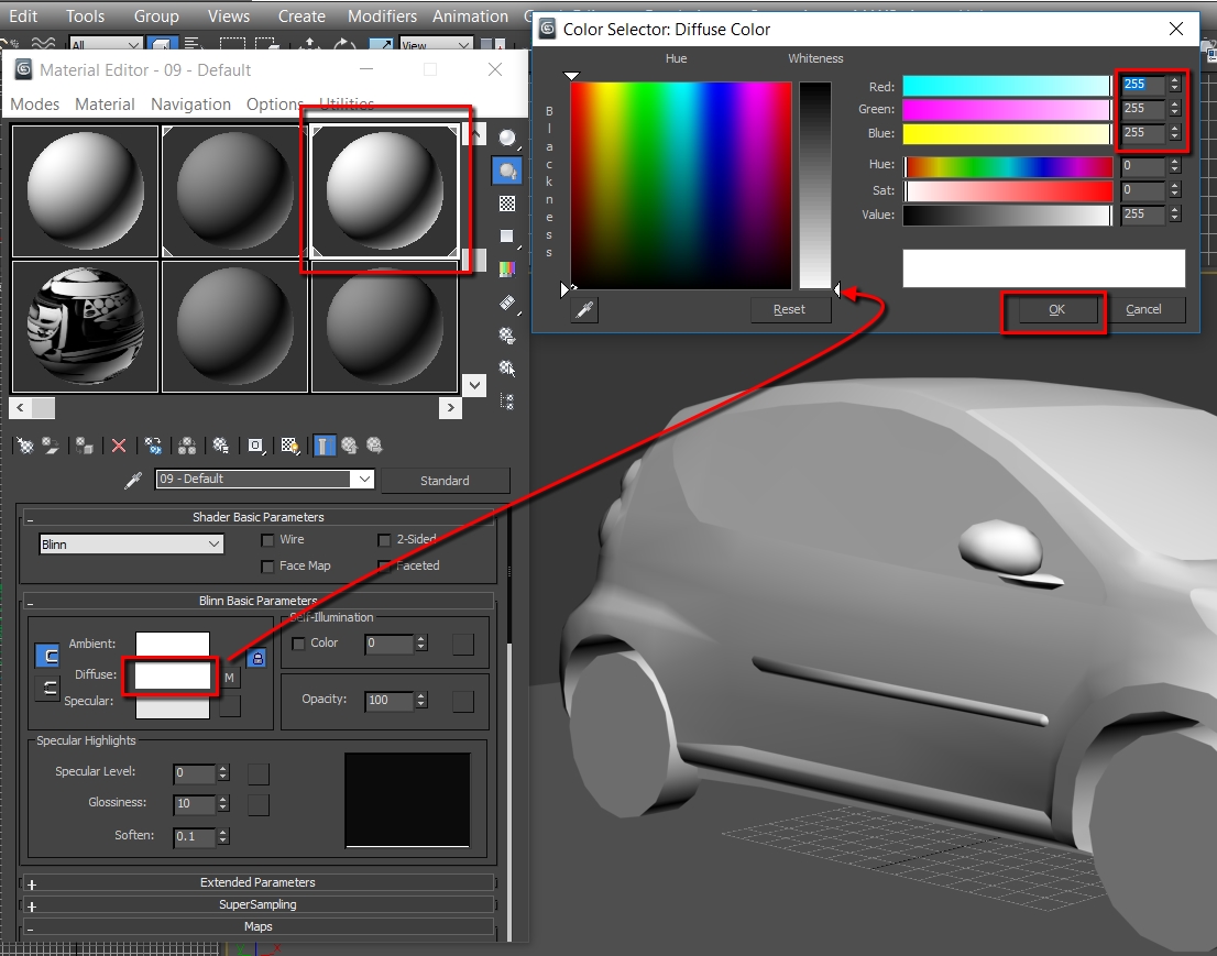
2. Similar as in step 6 of VRay instructions, pick an empty Material. And just only set its color to pure white (255):
3. Apply this white material to the car (in the way it‘s done in step 8 of VRay instructions)
4. Do everything the same as in steps 9-12 of VRay instructions. BUT!, attach the base to the car model, and UV map it into free small spot in the UV map. Later base will be deleted.
5. Do everything the same as in steps 13,14 of VRay instructions, only the texture type should be LightingMap (instead of VRayGlobalIllumination)
Just don‘t click Render yet
6. Place a Skylight in the scene, it should also be pure white:
Create -> Lights -> Standard -> Skylight.
Set Sky Color to pure white
And finally place anywhere in the scene you want.

7. Now click render
8. Once rendering is finished apply the rendered texture to car model (instructions are in latest VRay part)
I am not satisfied with the result this method gives, so I advice you to use VRay. Or also try Mental Ray.
Don‘t forget to paint wheels in single constant color (in AO texture). Because wheels are spinning in the game. It would look weird if one part of the wheel was bright and another part dark.
Here ends AO rendering workflow, AO is optional of course, but it gives a new level to a realistic look.
Do not restrict youself only with this tutorial, you can find many guides about AO rendering in the internet, maybe even more efficient and better looking than mine.
Diffuse Texture Baking
Here high-poly model comes into play again, we will need to bake textures from it.
Unfortunately I won‘t cover how to do it in this tutorial.
Here are the links how LOD textures are baked from high-poly model. In our case instead of LOD, it will be our main car model.
First option is better for multi-material high-poly models
If you find it difficult, and want it to be in this tutorial, inform me, and I will update it.
Once you have baked the texture from the high-poly model. Open it in image editing software. Create a new layer, set it to Multiply (blending mode). Paste AO texture in this layer. Most of the time baked texture has many faults, so you will need to manually edit it, until result is acceptable fo you.
Before -> After example:


LOD Making
Make the LOD in the same way we made the main model (we worked on recently) – in Mesh Modelling tab..
LOD is a new model and main model should be the Surface to be drawn on.
There is no need to render AO for the LOD model, because textures are baked from the main model which already has AO.
Bake the textures in the same way as I told in Diffuse Texture Baking tab.
My final LOD:

And the texture, 128×128:

THE END and Notes
Here my tutorial ends.
As the name says it is a car modelling tutorial.
The rest of procedures not mentioned here:
- Making other textures.
- Exporting as fbx. (tick Smoothing Groups before export)
- Importing into Asset Editor and saving the asset.
These things are covered in Skylines Modding wiki and our community texturing tutorial:
Skylines Wiki – Asset Editor[www.skylineswiki.com]
Texturing & Asset Creation 101
Have fun modelling!
Free 3D model sources:
Archidom[www.archidom.net]
DMI-3D[www.dmi-3d.net]
[link]
[link]
I use jazzycat’s models[jazzycat.ucoz.net] (conversions) for ETS2 as high-poly models. Since I don’t directly re-use his models – I make everything by myself just having his models as reference. Also jazzycat is not the true author of the models. So there is no copyright violation.
To get his models into 3Ds Max we need to use Blender with Blender2SCS (or SCS Blender Tools) to import pmd. files and after that export to fbx (3Ds Max compatible format)
In case of some questions contact me in Steam or in Simtropolis, or in Paradox forums.
PDF version of the tutorial (from github)[github.com]
DeviantArt picture used for thumbnail[kentinhozdr.deviantart.com]