Overview
In this guide, I’m going to show you the 4 or 5 different methods I use for creating shapekeys in Blender. I’ll concentrate on Facial Flexes in this document and just give the basics. It will be up to you to research further tips and tricks on the net. There are tons of How To videos out there if you want to explore ShapeKeys further.Another thing, creating GOOD and REALISTIC shapes takes time and effort. The shapes I create here are rough and quick (in other words not my best work), but I think you’ll get the gist and with practice will be well on your way.There are A LOT of pictures in this guide and most of them are GIF images, so it may take a while to load. Most images are high-res so if you have trouble seeing what is going on, Click the image to open a larger version of it. Because I wanted to keep all images used in the guide on Steam and because of the 2mb upload limit on images on Steam, some GIFs have been sped up shrunk and low-res. All I can say is “Sorry, Blame Steam for setting such a low upload limit.”Any Spelling or grammatical mistakes are intentional, just to pester those who purposely look for dem kinda tings so they can beach aboot ’em. I won’t be covering the use of Corrective Shapes or their drivers in this document.
What is a ShapeKey
In a Valve model, we know these as the Flex Sliders we use to pose the face and eyes to give our poses and animations expressions. However, they don’t necessarily have to be restricted to this use.
For example, it is a cheap way of hiding a Misc item, like a mask that you have on a model and don’t want to use a body group. You can use a shapekey and shrink it into a body part and hide it. The Spy’s ciggy is a good example of this and MMD dolls are notorious for this, hiding all kinds of mesh objects for the different expressive eyes, mouths, wings, bracelets, jewery and whatever else they can get away with.
What a ShapeKey is, is a method of moving mesh without having to use a bone. They are also known as Vertex Animations (or if you’re using Maya, I think they are called BlendShapes.) As I don’t use Maya, so we’ll be using Blender here and creating ShapeKeys. The version of Blender I am using is 2.79, but things have not changed much since 2.50 as far as ShapeKeys are concerned.
You have to be careful when deciding whether or not to use a shapekey or if a bone is required. The reason for this is that a bone will rotate a whole object without distorting it, where a shapekey moves vertices in a straight line from the start position (the basis) to its final destination using the shortest route.
For example, you would not want to use a shapekey to turn wheels on a vehicle. And here’s why…

The basic rule of thumb is: If you’re going to rotate an object (especially over huge distances or a high number of degrees), then use a bone. If you’re moving an object a short distance and in a straight line, consider a shapekey.
Anyway, how you use them is entirely up to you, after all it is Your model.
There are other restrictions that will occur when using shapekeys you need to be aware of, but we’ll look at those when we run into them.
Things to Be Aware of When Creating ShapeKeys

I have been asked many times… “Is it better to model using Quads or Tris?”
For those who don’t know what I mean by this… The model I’m currently using in this tutorial was modelled in Quads.
In a model that is done with quads, most of the faces in it will have 4 corners. The only Tris or N-Gons you’ll find will be where quads just won’t work.
In a model done with Tris, most of the faces in the model will have 3 sides, (made of triangles.)
And a N-Gon is a face that has more than 4 vertices. A model will not be done completely in N-gons.
In my opinion, N-Gons should be avoided whenever possible and only used on mesh that isn’t going to deform or be bent. Where weight painting of only 1 bones is applied equally to all the vertices of the n-gon.
Using quads make is easier to extrude faces when retopoling high poly meshes. They also allow the use of looping tools like adding loop cuts and edge sliding for adding topology and sharping edges. The downfall of quads is that they don’t bend easily and when trying to make curves in mesh, they can cause sharp edges. A smoothed round object ends up looking like a hexagon or octogons type thing.
Mesh deforms are blocky because your trying to bend complete squares of mesh.
However, it is easier to break a quad into a tri when required than it is to convert a tri to a quad.
Using Tris adds more mesh (topology). It’s easier to control things like bevels, curves and angles in the mesh.
The downfall of Tris is that you lose the ability of using looping tools and adding topology is harder, you can’t just extrude an edge and drop it. With Tris, you can’t select loops, even if the connecting verts make a perfect loop and edge sliding does not work. If you need or want to slide an edge, you have to slide it one vertex at a time.
Mesh deforms are smoother because there is more mesh and the bends happen over triangles rather than squares.
But getting back to the original question, which is better? Well both are and it’s a matter of preference. Experiment with both, then you decide.
The first shapekey you’re going to create on any model is the Basis Key. This is done in Object Mode and usually created with the object in its “Rest Position”. New keys are then created in Object Mode and will be based off of the Basis Key.
Once a Key is created, it can be named to pretty much anything you want AS LONG AS THE NAME DOES NOT CONTAIN AN UNDERSCORE (_). If you are creating a model for use in the Source Game Engine, an Underscore is used by Blender Source Tools to identify a special type of ShapeKey known as a Corrective Shape. I will not be covering Corrective Shapes, their use or how to initiate their drivers in this document.
You “should” name your shapes after you’ve created something you’re happy with, this way you can quickly see what a shape is and remove the chance of wasting time duplicating shapes that already exist.
Before we start, there are a few buttons, switches and a couple of huge restrictions that you need to be aware of in Blender.
Let’s start with the restrictions.
- Ensure the object your going to assign shapekeys is joined or spilt form other objects so that you don’t have to attempt to join objects when finished.
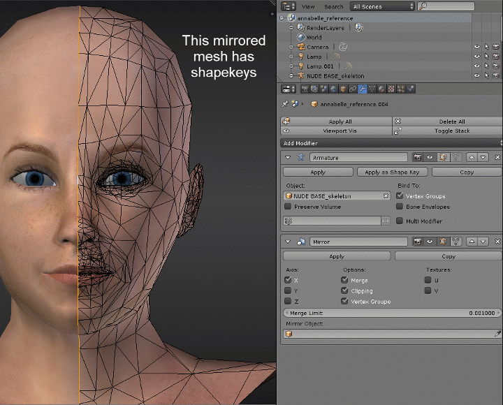
In other words, if you’re working on a head, make sure things like the eyes are joined to the head object, hair is separated from the head object, or if you’re going to have the whole body as one object, that everything is joined into that one object before you start. - Make sure you have modifiers like Mirrors, Solidify, or any modifier that manipulates mesh, are APPLIED before creating the basis key. (Armature modifiers do not have to be applied.)
- Some modifiers will not allow you to add shapekeys.
Now the reasoning behind those 2 statements above.
- If you are going to export SMD type Source Files for compiling, the shapekeys are going to create a VTA file. This VTA file contains all the vertex coordinates in a model.
When compiling the model, you have to declare your flexes and your flex controllers in your QC file.
As a model can only define the shapes for 1 VTA file in the QC, if you have multiple objects (or bodygroups) that are being controlled by shapekeys, you “may” find either the flex definition has been dropped from the compiled model or the flex does not work. Period. - The reason these type of modifiers must be APPLIED is that shapekeys affect vertexes. This means that if there is a shpekey on top of mesh modified by a modifier, then the shapekey is going to affect the mesh created by the modifier the same as the mesh that the shapekey was created with. In the case of a mirror modifier, the mesh created by the mirror would move extactly the same (or opposite to) the mesh the shapekey was created with.
Sometimes this is a good thing, until it comes time to apply the mirror. If you try to apply a modifiers that has a shapekey in the object, Blender will not apply the modifier. The apply will error out. The only way to get through a modifier that errors out because of shapekeys is to delete the shapekeys, apply the modifier and do the shapekeys again. (Maybe!!)
There are a number of different modifiers that will error out because of shapekeys, so it is best to test them and apply those that do before starting to make your shapeskeys. Just adding a basis key and then try to apply a modifier “should” cause the error, (there is nothing worse than creating 10 or 20 shapes only to find out you can apply a modifier). So if you do have modifiers on the object you are going to make shapekeys with, create a basis key and try to apply your modifiers. If they take, Use Control + Z to backout the apply and try the next modifier. Repeat the steps for each modier added. If they all allow you to apply them and not error out, you should be fine, but if one of them do Error out, then That modifier has to be applied before starting your shapekeys. - The same thing applies to adding some modifiers if shapekeys exist. Blender will not allow you to add new ones or modify existing modifiers.
- ALWAYS ensure that you have the Basis shape selected before attempting to add new modifiers. The Basis Key is the position your model when it is in when it is in its Rest Position.
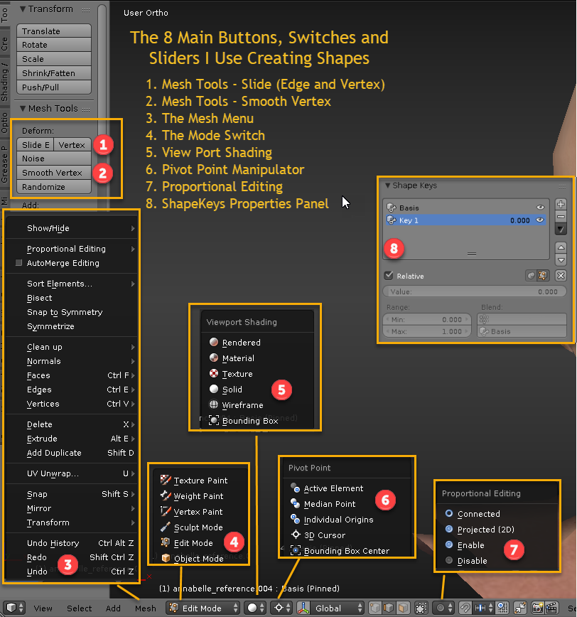
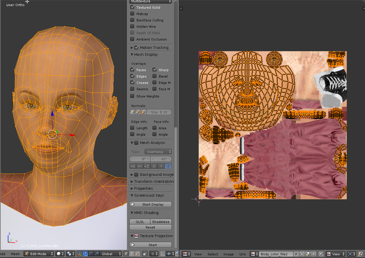
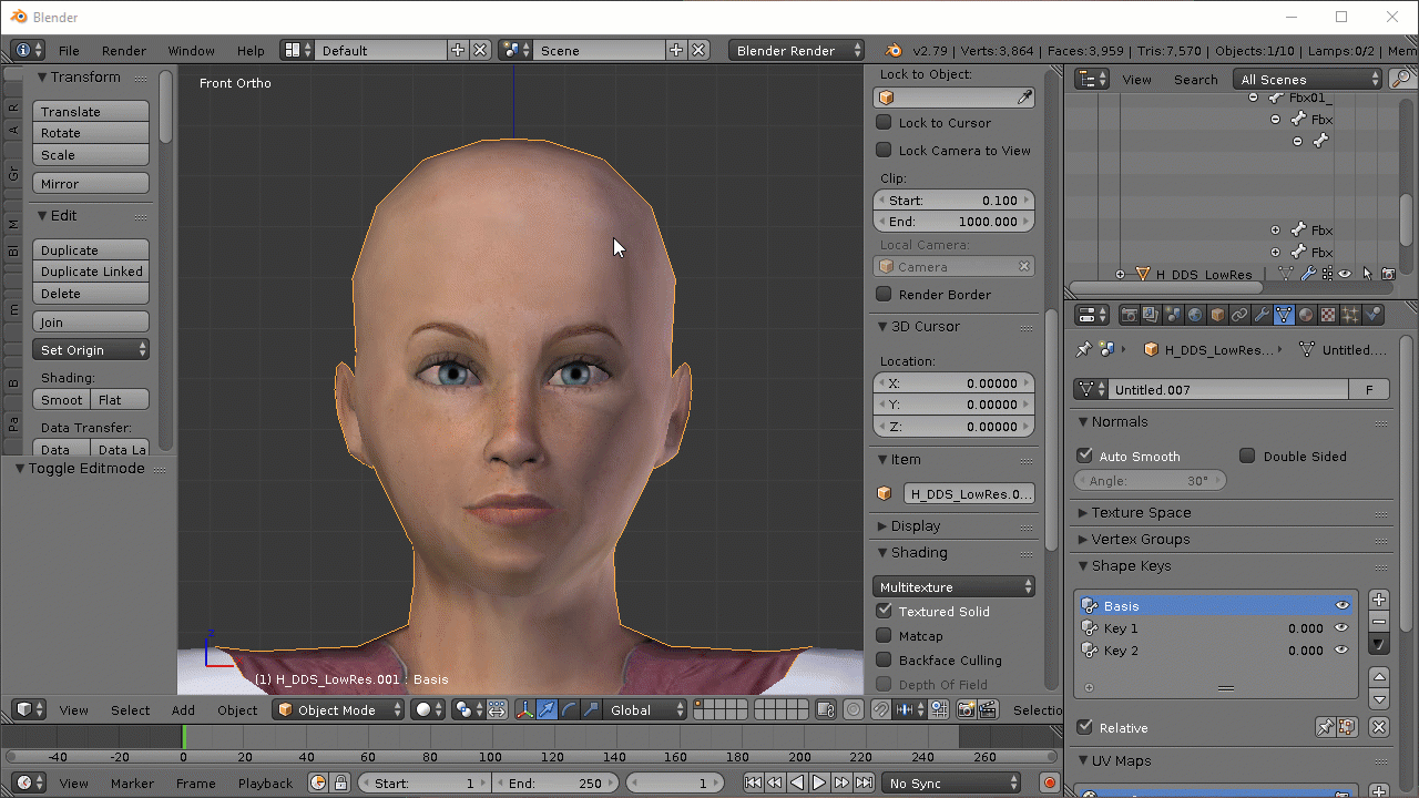
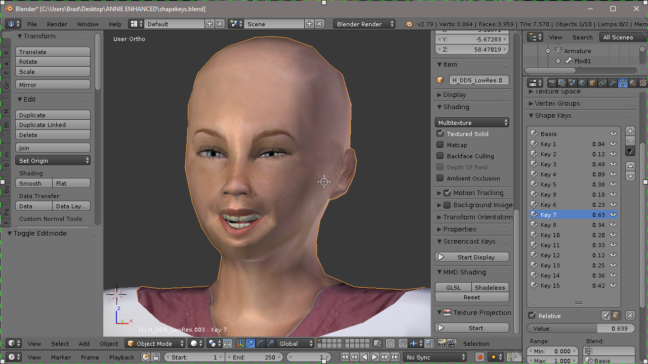
Buttons, Switches, Sliders, Menus Used
This images shows the main locations of the different Blender controls I use when I make shapeskeys. When I start explaining the methods, these are the controls I’m referring to.

When using a Blender Function, always check the bottom of the Tool Property panel. You may find additional operator options that allow you to limit or change the way the tool operates.
Method 1 – Create Shapekeys from Scratch (Part 1)
In this section I’m going to give you the Basics of how to make shapekeys from scatch. The reason why I say Basics is because
1) no one want to sit through 3 full length motion pictures of watching anyone create shapekeys for one model, and
2) I could sit here for hours creating different shapes but as you lookd at the picture that I would create, you’re going to find that all shapekeys use the same principles. Grab a vertex, set up how you want it to iinteract with its neighbouring vertices, set the pivot point and move it. Finalize the shape by smoothing things out, adjust movements and name.
So, all I’m going to do is show you a few examples using GIF images and let you figure it out from there.
Creating shapekeys is an acquired art form of practice, practice and more practice. Each model is going to present its own unique challenges and problems as you develop your shapes.

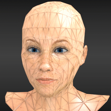
The model I’m using is an Annabelle model provided by GoryGirl (she and a few others have asked me to do a tutorial like this.) I don’t know where she got it, so I can’t credit the original author (and as such this model will never be uploaded to the workshop by me…)
The original model was an FBX type model, so the first thing I did before starting anything was scale the model to the size i intend on exporting in Object Mode. I then Select all objects in the scene and APPLIED the Rotations, Scale And Location so that all object have a location and rotaion of 0, a scale of 1. The Origin Point for all objects is 0,0,0 on the Blender Work Grid. If the feet are no on the ground, I move ALL the objects in Object Mode until they are and re APPLY the Rotations, Locations and Scale values again. This is a standard step for any model you plan on porting.
Now to set up the model itself. This model consists of 7 objects, The body and head are one object, 2 eyes, 2 eye glands and 2 teeth objects (The upper and a lower) In order to make shapes in the head, I want to change this to 2 objects, a head object which will include the head (and a portion of the neck and shoulders), the eyes and the teeth and an object that will include the lower body. (I plan to use bodygroups for that part to give her different bodys). But in order to get the shapekeys to work properly in the head, I need to split it out and join the other objects to it.

So in with the Body object in Edit mode, I would select something like this, Press P and separate it into its own object. (I have the eyes, glands and teeth object in xray mode here so you can see that they are indeed their own objects.)

Remember in the things to be aware of section I said that You can’t have shapekeys affect mesh across different objects, so what we have to do now, is join the eyes, glands and teeth objects to the new head object and make the thing I’m going to add the shapekey to, one object.

So in Object mode I select the objects I want to join together by holding the Shift Key and Right Clciking the objects I want to join together ensuring the last selected item is the Head Object. I then press Ctrl + J to join them (or use the Join button in the Tools Panel on the Left of the 3D Viewer.)

The last thing I do is apply the textures to the model. This way I can see how the shapes are going to affect the actual textures on the model.
As this is a really low poly model, making shapes is harder, there is more mesh spread out in the faces and getting a really good shape can be a problem. You could add more topology by adding loops or by subdividing the mesh (not a subdivison subsurface modifier), but for this tutorial we’ll work with what we have.
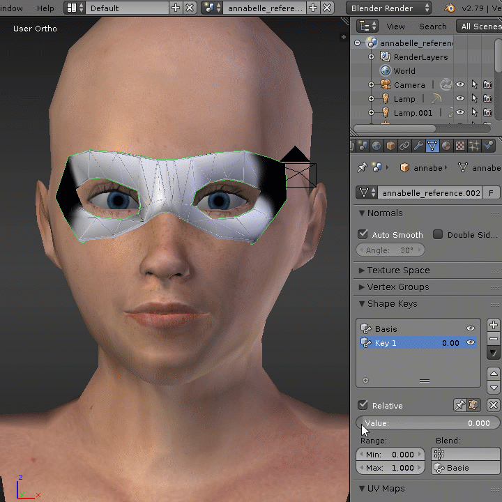
Valve models with advanced Eyes (the pupil interacts with the eyelids) require 2 principal shapes in order to work. The upper Eyelid full down and the bottom Eyelid full up.
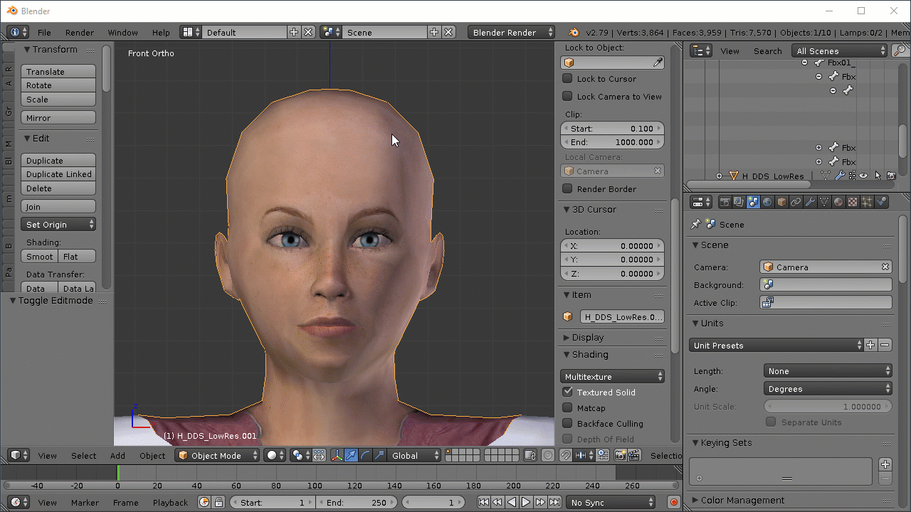
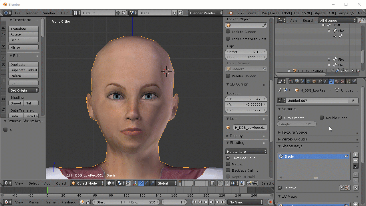
With the model in Object mode and the head object selected in the 3D Viewer, select the Data Object data tab in the properties panel. Scroll down to shapekeys and ADD a key by pressing + button beside the the panel. This should be the first shape and will automatically be name Basis by Blender.
Remember the Basis Shape should be the Rest position of your model, all the verts in their unedited space.
Now click on the Modifier Tab in the properties panel and check for any added modifiers. Remember I said the Armature Modifier does not have to be applied, but if you have any other modifier try to apply it. If it does not cause an error, use Ctrl + Z to back out the change and move on to the next one. Do this for every modifier you have. If it does cause does cause an error and tells you the modifier can not be applied because of shapekeys, go back to the shapekeys panel, delete the Basis shapekey, then apply the modifier. Fix any mesh you have to then start the shapekey process over again.
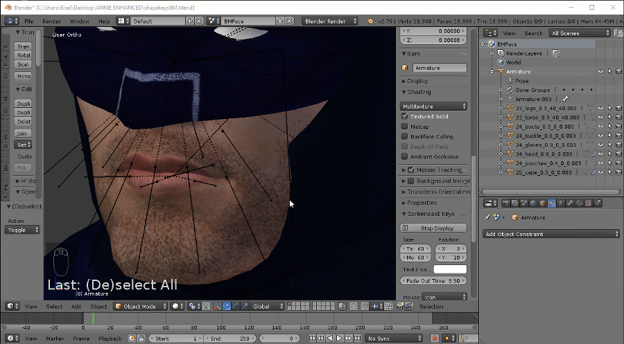
There is another test you should do at this point and that is to check for non-manifold mesh. MMD models are particularly bad for this condition. What non-manifold mesh is is mesh that has been pieced together and not welded to the mesh around it. The mesh may contain a lot of unnecessary doulble and can be subject to splitting when shapekeys are introduced.
To check for Non-manifold mesh, put the model into edit mode, change the view mode to wireframe, use the Select Menu option and go to Select by Trait then choose Non Manifold

This model is good, the only non-maniold mesh found are the mesh end points of the things that make up the object.
This is an example of a MMD model that has a severe case of non-manifold mesh and what can happen when you try to add a shapekey. See how the mesh falls apart when moved?
To get rid of the condition you have to select the non-manifold edges and remove doubles. But, caution has to be observed because you don’t want to remove doubles where they are required to separate things. (Like the gaps in teeth, welding the end of a tongue to the teeth or lips, or welding lips together.)

Like this: (this is the same model shown above) Selecting the NonManifold (in Edge Mode) edges we find that the model is suffering severely. If we try to shape, the model falls apart. To cure, select the Non Manifold edges and remove doubles (1117 in this case). Now try to shape.
When you’re happy with the mesh, get back into object mode.

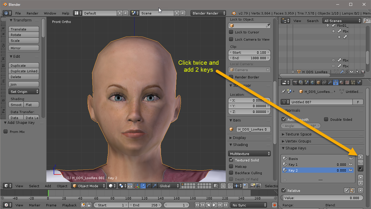
Now while still in Object mode and with the Basis Key selected, click the + button twice more to add 2 Keys These should be named Key 1 and Key 2 by Blender. (Blender will not allow you to add shapekeys unless you are in Object Mode.)
Select Key 1,
make sure the Relative check box is checked (it’s above the shapekey influence slider),
slide the influence slider to 1,
then put the head object into Edit mode and
select Vertex Editing.
If you find that the Shapekey influence bar is greyed out and unchangeable when in edit mode, click on the 2 buttons beside the Relative checkbox until the click combination make it active and you can slide it. You’re going to need to be able to do this ability to check the mesh movement as you apply the key.

Method 1 – Shape 1 (The Top Eyelid)
Now that Blender and the model are set up for doing Shapekeys, let’s do the Eyelid Down shape
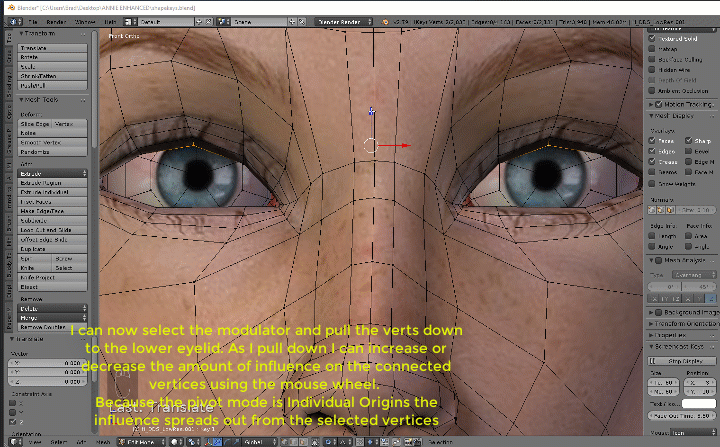
With the model in Edit Mode and the select mode in Vertex Mode, Press 1 on the NumPad to lace the model into Front View and make sure it is in Ortho Mode (NumPad 5). Zoom in on the eyes and select a vertex from each upper eyelid. Try to make the selections as symmetrical as possible. Change the Pivot Point to Individual Origins and turn on Proportional Editing in Connected Mode.
More Set up…


Take hold of the modulator axis indicator that will pull the selected eyelid vertices towards the lower eyelid (In my case it’s the Z Axis). As you pull straight you can increase or decrease the amount of influence passed to the connected vertices using the mouse wheel (Up, increases the range. Down, decreases). Don’t worry if the lid does not completely close the eye.
Finish the shape by selecting vertices that you need to and pull them into position, increasing and decreasing influences as required.
After finishing the shape, back away from the model a bit and use the shapekey slider to view it.

This is pretty good for a rough shape but it needs to be fine tuned if I intend to use it as my base shape for Valve advanced eyes that use Eyelids. I’ll get into editing shapes in another section.

Method 1 – Shape 2 (The Botttom Eyelid)
So when we started I told you to make 2 shapekeys when you created the Basis shape. We’re going to use the Key 2 to pull the Bottom Eyelid to the top of the eye. This shape along with the one we just completed are required if you plan to have your model use the advanced eyelids where the eyelids work with the pupil like this…
I cover advanced eye flexes in my Blender to SFM guide.

Before starting the next shape, ensure that you clear any active shapekeys. If you don’t and you start making your shape, the active keys will be added to the new shape. To clear an active shape, either select a shape where the slider value is greater than 0 and reset the slider to 0, or a faster way to clear all active shapes is to use the X button.

Select the next available Key, set the slider value to 1.00 and do the same thing you did creating the first shape.
Select 2 symmetric vertices on the bottom eyelid, make sure proportional editing is on, and pull the verts to the upper eyelid, adjusting the influence as you go. If you find that things aren’t moving the way you need them to, release the mouse button then reclick it and pull. Releasing the Mouse button makes what you did permanent and resets the influence on the connecting verts based on their position when you released the mouse button.
If you find that pulling one vert isn’t working because of the way they are positioned, try selecting 2 vertices on each lid.

When you’re happy with the shapes, back away and test them. What you’re looking for is clipping, if the shape looks natural, and if the lids close completely. If you end up with the eyeball clipping through the lid as it closes, consider selecting the eyeball and pulling it back a bit into the head as the lid closes. You can pull the whole eyeball back or just the verts that are clipping through.
Again, this new shape needs some editing in order to be used for advanced eyelids, and again, I’ll get to that in another section.

Method 1 – Shape 3 (Nostral Flare and Pinching)
Now we’re really going to see where Proportional Editing comes into play. When we wrinkle our noses we don’t use bones to move the flesh, we use muscles. There’s no rotation, just muscle pulling and stretching flesh. This is the way you should think when creating a Shape, this is the muscle that is moving flesh of the model. It is not a bone. Bones rotate at a joint, muscles stretch and pull.
The shapes I create here are exaggerated to show the process. Like I say, good and realistic shapes take a lot of time and practice to make and using low poly mesh like this only makes it harder.
(Gifs images are getting harder to produce now because they are getting longer and more involved, I will be losing some resolution but you should still be able to get the jest of them.)
Let’s get started.
Take the model back into Object Mode and add some more ShapeKeys. (I’ve added 3, Key 3, Key 4 and Key 5).
Now take the object your creating the shapes on back into Edit Mode, Clear any active shapes, select the next Key (in my case Key 3) and set the slider to 1.00
In this shape, I’m going to make a Nose Flare, so I select symmetric vertices on each side of the nose and I set my Pivot point to Median Point. By setting the Pivot point to Median Point it means that the influences are going to be applied from the CENTER of the vertices selected when I use Porportional editing.
This time instead of Pulling verts, I am going to use Scaling, but only on one axis (towards the cheeks or on the X axis in my case).
Not my best work, but for this tutorial it will almost do.

One of the important things here is that the skin under the nose is expanding as the nose flares. However, when we flare our noses like this, it has a tendencey to lift a bit too. So, to achieve this effect while still using Key 3, I change my view to side Ortho mode (NumPad 3), change my pivot point back to Individual Origins, select a vertex on the tip of the nose and pull it up and back a bit.
Notice how the proportional editing moves the connected vertices which creates the illusion that the muscles are not only moving the nose, it’s also affecting the skin under the nose. When we start working the mouth, I’ll introduce you to the smoothing and sliding tools to further develop the illusion of muscles acting on the skin.

Pinching is the opposite, instead of scaling outward, scale inward .
Clear all active shapes, select the next available shape key, go into edit mode, set the key slider to 1.00 and start shaping.

Method 1 – Shape 4 (mouth, tongue and teeth)
In this section I’m going to demonstrate here some of the other Blender controls that can be used to assist in the making of a shape. These controls are Edge and Vertex Slides, Vertex Smooth, remove Blend from Shapes and mirror shape key. There are powerful tools when working with shapekeys and can help create the illusion of muscles moving the skin when the shape is applied.
Let’s get started… If you don’t have any shapekeys left to work with, place the model into Object Mode and add some.
Place the object you’re working with back into edit mode, Clear any active shapes using the shapekey X button, select the next available key, set the shapekey slider to 1.00 and begin making your shape.
Again, my shapes in this section are going to be exaggreated to show processes. You take your time and make good shapes, the guide isn’t going to go anywhere while you work.
Just as a note here, you can create shapes in all the selection modes (ie vertex, edge and face selection modes). Just remember that the more mesh you have selected different modes is going to affect the way proportional editing is going to move the mesh.


Notice the way the proportional editing performs with more mesh selected via the selection method. The more mesh selected the blockier the movement is. This is why I usually only use Vertex Select and make my shapes this way. It gives me better control as I pull, push or increase/decrease influences on the selection.
The first shape I’ll try is a simple smile. This really really rough shape took 48 seconds to create (just to give you an idea of how much I have to ramp up the frame rate on these GIFs.)
Notice that once again, I only have 2 vertices selected and I’m using proportional editing pull and push the connecting vertices. If I wanted to make a smirk on one side, I would have only selected 1 vert on the side I wanted to make the shape. But there is another way to do this that I’ll cover later.

Also, you can see that I don’t have to stay in Front and side ortho View mode while editing. As long as I have the Transition Orientation mode is set to Global mode and use the gimbal’s modulator indicators to pull the mesh, the verts are going to move only on the axis I select.
HOWEVER, you’ll notice that I do return to Front Ortho View Mode before I scale the mouth wider. This way I ensure that the scale is applier evenly over the x, y and z axis.
I can control which axis the the scale works on by pressing S (for scale) then the x, y or z key to select the axis I want to constrain the scaling to before I scale.
Or if I want to scale on 2 of the 3 axis I can press S (for scale) then Shift x, y or z to not scale on the select axis.
(Confused?? for example if I press SX then scaling will only take place on the X axis.
However, if I press S(shift)X then scaling will take place on the y and z axis. Scaling on the X axis will not happen.)
Now we’re going to open the mouth. Eventually the GIFs are going to have be split up because of the image size limits place on uploaded pictures if I want to keep the image in the guide. (I’ll let you know when I have to do this.)
In edit mode, Clear any active shapes, select the next available shapekey and set the slider to 1.00.

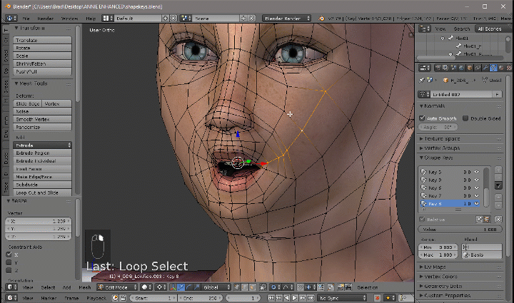
Ok here I selected 1 vertex on the lower lip. Using the same techniques as before, modelled the shape letting proportional editing move the connected vertices. Because the teeth and tongue are not connected to the mesh that the lips are, I had to select and move them separately.
This is why separate objects that are going to be affected by shapekeys “should” be joined into one single object.
If the Teeth were a separate object, I would have had to go into Edit mode on that object and create an entirely separate shape for it. My user would have to manipulate 2 flex controls to achieve the shape I just created.
Usually when a mouth opens, it is done so by moving the jaw bone, but becuse our model doesn’t have a jaw bone, we have to simulate the illusion using shapekeys. We’ll get into that when I show you editing and smoothing.
Ok, let’s make an O shape.
In Edit mode, clear any active shapes, put the model into Front Ortho View mode, select the next available key and set the slider to 1.00. (If you don’t have an available shape key, back to Object mode and create more.)
This shape took over 3 minutes to complete, Gif is split into 6 parts
Ok, That’s enough manual shapes for this tutorial, but if you’re trying to work a model while using it, keep going and add more shapes. But you might want to explore the rest of this guide before you do. You just might find some real time saving tips.


So, let’s move on to editing.
Editing, Smoothing and Deleting Vertexs from Shapes
I’m going to work with the smile shape here. I’ve duplicated the shape to a new key (something that will be shown to you later) so we can see the difference after the edit.
In this shape, the only vertices moving are the ones that are near the yellow circle, when in fact most of the vertices in the black boxes should be moving. (Even if it’s just a smidgeon.) Don’t believe me, grab a mirror and smile at it. Watch what moves.
As a matter of fact, keep the mirror near the computer. It’s an excellent tool for creating a reference. When having a problem making a facial shape, pick up the mirror and make the face you’re trying to create, then copy what moves in the mirror to the vertices in the shapekey.

So how do we fix this shape to look more realistic?
Select the shape you want to edit and set the slider to 1.00.
Now model the vertices you think should move to their final resting spot.

(which is going to result in a flurry of questions to me starting with “WTF” or many will just rage quit Blender, throw their projects in the trash and forget they even tried.)
So, before you start pullng and pushing vertices, let me introduce you to some tools that are going to make your life a little easier.

Just pushing and pulling vertices will not do, especially with proportional editing turned on. Because of the 3D environment, the vertices are going to pull away from the line you want to maintain. Using things like edge slide and vertex slide (with the options they give you), the vertices your moving are going to follow the line of the existing mesh.
Using things like Smooth, Noise and Random are going to create a bit of realism.
The Vertex menu option called Blend From Shape is going to allow you to adjust the end position or remove a vertex completely from a shapekey.
There are other plugins out there with tools that will assist you with creating shapes, but let’s just keep this to the stuff available in the basic version of Blender.
This is one of the reasons why I like Quads when modelling shapes. I can use the edge slide method to move vertices along an existing mesh path. If the model had been done in Tris, I would have had to move the vertices one at a time using the Vertex Slider.
(Editing these shapes took around 3 minutes, GIFs have been sped up and clipped into segments for upload. Because the upload limit is only 2 megs per image, they have lost a lot of resolution. The final chin movement is a proportional edit vertex pull)


What I’m doing here is selecting an edge of vertexes, setting the shapekey slider to 1.00 then selecting edge slide in the tools. I then pull or push the selected verts along the mesh path to where I want them to end up.
If you look closely at the 4th image, I select a group of edged that create selected faces, The Edge Slide function does not work until I change the selection back to just edges (image 5).
The vertex slider works pretty much the same, you select a vertex, set the slider to 1.00, click the vertex slide button and then slide the vertex on the mesh path in the direction you want it to go.
The Smile is now looking a little more realistic. Again, I’m hurrying through these shapes. Just remember shapes will be only as good as the amount of time you give to create them. So take your time to achieve better results.

You have to be careful when you use these buttons. Too much smoothing can change the face of a fairly good looking model into the face of a Grey Alien really quick. These tools do have operators that allow you limit he way it works, but if your not care, the deforms can be drastic. These tools average movements based on selected vertices.
Let’s try to fix the O animation using these tools.
As you can see, it’s all a matter of modelling, playing with the tools, and trial and error.


This is an extremely powerful tool. With it I can edit the the distance a vertex moves in the shapekey animation or delete it vertex completely from the animation.
So you’re working away and you notice that you have vertices moving in a shape that you don’t want to move at all. You could “try to edit” them back into there original position, but even after playing with them for over an hour, they still move slightly and it throws off the shape completely. You REALLY need these vertices to stay in place.
Remember this…

This is where this tool comes into play.
This tool also allows you to adjust how far a vertex will move during the animation. You can cull out travel or add distance to it.


For example in this animation I allowed the selected loops to travel too far and butt against the next loop. This will cause a sharp crease in the eye area of the model. I need to cull down the travel.
So here’s what I do


After making this edit I find that the selected verts only travel to the .429 mark over the length of the shapekey and stop.

Couple of things to remember when using this tool to subtract from shapes.
- If you use the Value 0, it means, don’t change anything for the selected vertices,
- Values .0001 through .9999 moves the vertices in the direction of the shape change. The LOWER the number value, the farther they travel
- The Value of 1 means delete the selected vertices completely from the shape.
- Values 1.001 through 2 means move the selected vertices in the oppsite direction.
- The active change will remain active until you select new vertices and relaunch the tool.
And that’s it for Editing Smoothing and Deleting Shapekeys.
Method 2 – Creating New ShapeKey From Existing Keys
Shapekeys in Blender are additive. What this means is that if you apply a shapekey on top of another, the additional keys add to the shape of the one before it.
If you have a model that already has shapekeys or you’ve created a basic set of keys from scratch, you can use those keys to create duplicate or new shapes using this method. (If you looked at the Editing, Smoothing and Deleting section I created a duplicate of a key of the smile shape so I could show the difference between the unedited and edited shapes. Well this is the method I used to do that.)
I’m going to use this method, the 2 shapes I made for the eyes and the Blend from Shape edit method to make a blink and a wink here. I’ll also create a some sort of shape from every Key I have available.
The Blink
This method is SO simple I don’t think I have to explain anything other than to post this GIF.

The Wink


This is also the method I use for creating Left or Right only shapes for things like Stereo Flexes.
I duplicate the shape twice, apply the shape, go into edit mode, zero out the the shape on one side of the center point and poof… I have a shape on one side. I repeat the process on the other duplicate shape, zeroing out the shape on the other side of the center point and I have the shapes I need for the stereo flex.
The Shape
Using this method is great for creating expressions from shapes you’ve already created. For example, I’ve add some values from every shape I have for this model in Object Mode and this is the resulting shape I’m going to create.

Happy to Sad (The Quick Way)
Let say you have a great grin shape and want to turn that smile upside down into a frown without doing it manually.
It’s pretty simple.
To flip a shape to its negative value of the original…

- Find the shape you want to flip.
- Change the Min slider value to -1.00
- THEN change the Max Slider value to 0.00,
- Move the slider all the way to the left (-1)
- then create your New Shape from Mix.
- Don’t forget to reset your original shape slider values back to Min 0.00 Max 1.00 after creating the new shape.
The new shape will have a min value of 0 and a max value of 1. Slide the slider and you have the
original shape now reversed in the new shape.
If you create a few good shapes, make left and right samples of them, then start combining them using this method, it won’t take long to make hundreds of custom shapes you can add into your models.
Method 3 – Using Bones to Create ShapeKeys (Head Bones)
A lot of models that are being ported into SFM come from XNA (XPS) models. Most of these models have an armature that have bones in the head for posing in the XNA Poser program. Well, we can actually create ShapeKeys by posing the head in Blender (It will also give us the ability to remove a lot of unnecessary bones after we finish creating the keys.)

(and no, I don’t have permission to port this model, nor am I going to ask for permission. The XPS model is available here… [link] )
So the first thing I do is import the model and scale it to the scale of the models I plan to us it with, then apply the Rotations, Scale and Location.

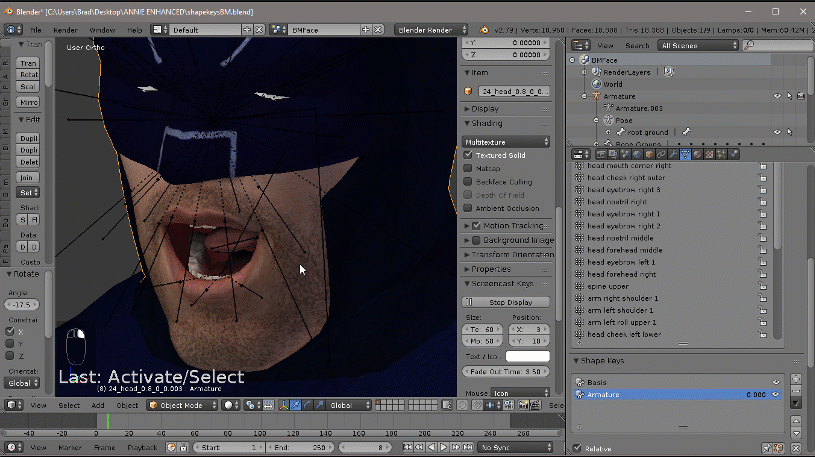
I then put the model into Pose(wireframe) mode, select all the bones that make the head except for the main head bone and pull the bones around a bit to see what moves and what doesn’t. If I see that something doesn’t move, then I grab the main head bone and move it around to make sure everything in the head moves. This particular model has 41 bones that make the head rig. If I’m struggling for bones to delete, after I finish making the shapes, I’ll be able to delete 40 of these. I need to keep the main head bone. (and here we go, Batman does the Funky Chicken)

The next thing I do is apply the textures (especially to the head). I want to see how the textures look when I pose the head for my shapes.

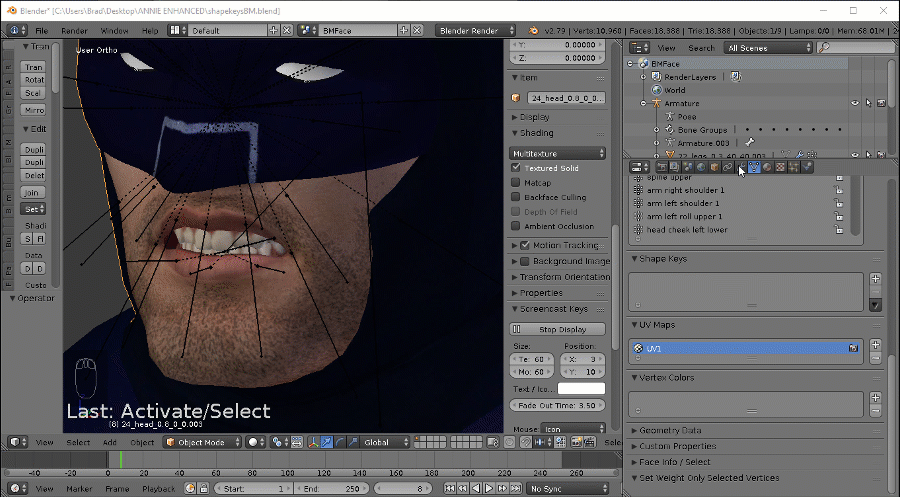
Now I have to prep the model for shapekeys and join the elements of the head into 1 object. So back into Object(wireframe) Mode, and using the Outliner in the properties Panel, I step throught the mesh objects and look for Objects I want to join together. (If I select an object and something other than the head lights up I can split it into a separate object.) So in this particular model I join the eyes, face, mask, teeth and the ref objects into 1 and rename it to Head so I can find it easier. Nothing needed to be separated.

Now that the model is setup, zoom in on the face, select the armature, go into pose mode and grab face bones and pose the face into the shape you want to make the same way you would pose any other bone. Just remember, you’re simulating muscles, so you want to pull and push the bones. The only bone you might want to consider rotating is the jaw bone. Also, some bones may be on top of other bones and hidden, you can use the Property Panel Outliner to select a bone (or bones) if you’re not sure what bone it is you’re grabbing. You can also hide bones you’re not using. (select a bone or bones, and press H to hide them. When you want to unhide them, press Alt+H.
Now, this is where the magic happens….
Once you have a pose you want to to turn into a shape,
- Exit Pose mode and get back into Object Mode.
- Select the the head object
- Select the Modifier Tab in the Property Panel and find the Armature Modifier.
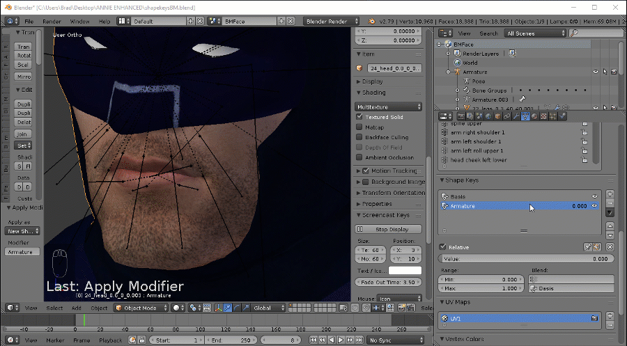
- In the Armature Modifier, click Apply as ShapeKey
As soon as you click that, the Armature modifier is going to disappear and the mesh is going to snap back to the rest pose.
- If you now check the Data Tab and look at the ShapeKeys panel, If this was your first Shape, a Basis key will be created and another key named Armature will be created. The Armature key will contain the shape you just created. Notice the shapekey is only moving the mesh, not the bones.
You should rename this Key now and give it a relevant name. - Go back to the Modifiers tab, The Armature Modifier has been “Applied” as a shapekey and you have to create a new one. Click Add Modifier and create a new Armature Modifier.
- Attach the Armataure Modifier to the armature you’re using and the mesh should snap back into the current pose.
- If you you want to save this pose so you can access it and build on it later, you can save it to your Pose Library. Go back into Pose Mode, Select the Bones you want to save for the Pose. Select Pose, Pose Library, Add Pose and follow the prompts.
(The Pose Library can be accessed via the Armature Tab of the property panel when the model is in Object or Pose Mode and the Armature selected.)
To reinstate a pose, select the pose name and click the magnify glass button. - Now to move on to the next shape, in Pose mode, Select all Bones (press A until all bones are lit up), select Pose, Clear Transisitions, All to to clear the current pose.
- Select the bones you want to move the mesh and create the next pose. Repeat these steps until you have the shapes you want to make, made.


The downfall of this method is that the mesh only moves in proportion to the way it is weight painted to the bones you move. This can be very limiting however, some models are really well done and the results are amazing.
Either way, the mesh is now a shapekey and can be edited, add to, smoothed, have noise added to it, etc as discussed in the editing section.
And that is how to add shapekeys from bone poses.
Method 4 – Mirroring Shapes from One Side of a Model to the Other
If you’re not comfortable with making shapes both sides of a symmetric model at the same time, you can create shapes on one side and mirror that shape to the mesh on the other side. For this to work, your model must be symmetrical on the X axis with the Z axis slicing the center of the model and it must be modelled with the front of the model facing the Y access. If your model is out, even a little bit, you can end up with some “pretty interesting” results.


This model is pretty much Symmetrical, however because it is made of Tris, there might be a chance the mirror from one side to the other may not work properly. All you can do is try.
Never assume that a shape mirrors correctly if they do take. Always test make sure they are correct and fix any problems.
See how much easier it is to see the symmetry in a model that uses Quads?

Anyway, I’ve made these 2 shapes on the left side of the 2 models and I want to attempt to create the same shapes on the Right side to a separate key.

Let’s try the Batman first. It is the less symmetrical.
The steps are as follow: In Object Mode
- Create a duplicate of the key you want to mirror to the other side.
- Select the Duplicate and apply the shape. Using the ShapeKey Dropdown Menu, Select Mirror shape and watch for errors.
In this case Nothing mirrored (what bender is trying to do is Flip the shape of all the vertices to the other side. So if this fails or we don’t get the dsired effect, we can try something else. Mirror Shape (Topology). - With the shape applied, use the Shapekey DropDown menu and select Mirror Shape (Topology)
This time 2772 vertices mirrored and 259 vertice fail, BUT, we end up with one of those pretty interesting results I was talking about eariler.
We can not mirror shapes from one side to the other on this model and will have to create shapes manually or with the bones. The failure could be because the Tris aren’t as symmetric as they look, OR it could be the fact that the mesh is weight painted to bones and that is causing the problem. (We’re trying to flip vertices painted to left side bones to the right side.) The only way to really find out is to finish making your shapes and delete the bones in the face (and vertex groups for them to get rid of weight info) then try the mirroring again. (Much to involved for this tutorial.)This is what is happening with this particular mirror process (easier to see in Weight Paint Mode)


So let’s see what happens when we try this with the model made of quads and doesn’t have facial bones.
The Process… In Object Mode:
- Duplicate the key you want to pass to the other side,
- Select the duplicate an apply it, then using the ShapeKey dropdown Menu, select Mirror Shape Key and watch for errors.
Again, the mirroring fails completely. This means the object is not as symmetric as it needs to be and here’s why… the 2 planes itersect at x0 and y0. You can see that a lot of the head is more into the -y area and this throws off the symmetry.
- When a Mirror Shape key fails we can try to mirror it by topology, so with the applied shapekey we want to mirror, use the Shapekey DropDown menu and select Mirror Shape Key (Topology) and watch for the errors.
This time the mirroring takes with 1016 verts being mirrored and 100 verts failing. When we Test amd compare the new sahpe with the original, things on the right side look good, but there is some movement around the ears on the both sides that shouldn’t be there.
These deforms can be removed from the shape using the “Blend From Shape” edit method I showed you earlier.
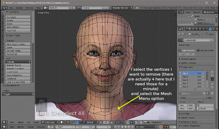
- take the object into edit mode, then select vertices that shouldn’t move by comparing the original shape with the mirrored shape. Select the mirror shape and launch the “Blend from Shape” and remove them from the shape.
I think that’s close enough to the original.


When we mirror by topology, what Blender more or less does is creates a duplicate of the object containing the shape we’re mirroring. It then applies a Scale on the x axis – 1 to flip it. From there Blender compares the mirror to the original object and move the closest verts of the original object to the matching vert location on the duplicate. Once the Verts have all been moved in the original object, the duplicate is deleted. Kind of like this.
Because the object is not 100% symmetrical, when blender compares the vertices, we end up with that extra movement in the scalp and the ears that we had to remove from the new shape in that last step.

A bit of a headache, but saves a heck of a lot of time because we don’t have to create the new shape from scratch (if it works.)
Method 5 – Transfer Shapes from Another Model
Much like Mirroring, this method is extremely limited and why I kept it for last.
Because Shapekeys move vertices, the movement is extremely precise (ie in this shape the vertex at 1200, 020, 6698 (x, y, z coordinate) moves to 1210, 200, 6785 (x, y, z coordinate)). If I try to use this method and there isn’t a vertex at the start location (or within a certain distance to the start location) in the model I’m trying to transfer the shape to, then Blender says, the models are not duplicates and the transfer fails. This applies to every vertex in a shape.
In most cases this process is used when you have made multiple models that use the same head. (For example, Instead of using bodygroups to change out outfits on a model, I actually make new models of them but use the exact same head in all of them. It allows me to create shapes only on one model, then use that model to transfer the shapes I made to the others so that I don’t have to waste time reshaping each model.
So in this part of this tutorial, we’re going to Head to Head

Once we see that fail (or happen, which I doubt), we’ll convert the Tris in the BatMan head to quads and try again.
So in this challenge, if the shapes transfer, Annabelle wins, if not, BatMan wins.
Then we’ll create duplicates of the Annabelle head, Remove the shapekeys from them and prove that the process “actually” works. (LOL)
Ok, let’s get started.
Here I’ve appended the BatMan head to the Annabelle Blender session. I’ve deleted the head bones with (exception of the main head bone). I’ve removed all the individual bone influences through weight painting and assigned the entire head to the main head bone (the head mesh needs a controlling bone in order to move with the rest of the model, Shapekeys aren’t influenced by this bone). Then I removed the unused vertex groups. I’ve left the shapes we created earlier.

The process for transferring shapes from one object to the other is this.
In Object Mode:
- Select the object you want to transfer the shape from.
- Go to the Shapes, select the shape you want to transfer.
- Holding the Shift key, select the object you want to transfer the shape to. (Both objects need to be selected with the object the shape is being transferred to being the active object)
- Using the Shape Key dropdown, select Transfer Shape and watch for errors.


So, let’s see if we can convert the Tris to Quads in the BatMan object (I say try because the object already has Shapes and Blender may not allow us to change the object) and try again. I’m expecting the same result.
To convert Tris to Quads:
- Select the object
- Take the object into Edit Mode
- If there are shape keys, make sure the Basis Shape is selected
- Press A a couple of times until all the Vertices are lit up (or select the mesh you want to convert if not the whole object)
- Using the Mesh Menu option select Faces, then Tris to Quads (or you could have used the Alt+J
shortcut key) - Check any Shapekeys to ensure they still work as intended.

Now that the BatMan object is in Quads, try the process for transferring shapes again.
Again the process fails. The same condition exists, the objects have different vertex counts.

The condition would exist if I tried to do this the other way, BatMan shapes to the Annabelle head and it proves that the object must be exact duplicates in order for the process to work.
AND BatMan Wins!
Ok, let’s look at Annabelle shapes to Annabelle heads that don’t have shapes and see if we can get that to work.
These heads are exact duplicates, the only difference is one has shapes, the other doesn’t.
Using the transfer method above, lets see if we can transfer shapes.

As you can see, the shapes transfer without warning or error. When tested they are exact.
So what would happen if the heads were exact, but one is done in Quads and the other in Tris?
To convert from Quads to Tris:
- Select the object
- Take the object into Edit Mode
- If there are shape keys, make sure the Basis Shape is selected
- Press A a couple of times until all the Vertices are lit up (or select the mesh you want to convert if not the whole object)
- Using the Mesh Menu option select Faces, then Triangulate Faces (or you could have used the Ctrl+T)
shortcut key) - Check any Shapekeys to ensure they still work as intended.

Ok, let’s try the transfer again.

Yes this is true, BUT, the vertex count didn’t change, and the vertex positions didn’t change. The Quads were halved into Tris. So in essence, as far as Blender is concerned, they are duplicates and the shapes are transferred.
But what happens if I happen to edit the head before transferring Shapes?


Poof The objects are no longer duplicate and we end up with the same error as we had with the BatMan transfers.

In Fact, just adding a single vertex is enough to break the ability of transferring shapes.
HOWEVER, What if we have a Scaled copy of the Donor object that has the exact same number of Vertices.

Well you’re good to go..
But check your transferred shape, it may not move as much as you want it to.

So the moral of this particular section, “The best practice is If you want to transfer shapes between objects, then the Receiving Object should be an exact duplicate of the Donor Object.” This way our shapes will transfer without a problem.
Closing Comments
I made a statement in the start of this guide saying that “You can not have Shapekeys on different objects of the same model.”
Well that statement is only true if you’re exporting SMD formatted source files that create a VTA.
If you are exporting DMX formated source files you CAN have shapekeys that affect different objects of the same model.
It is how I accomplish something like this.

There are two rules you have to follow though.
1) “You can not have a shape key name that is the same in both of the objects or you will break both shapes.” and
2) “You MUST export DMX Source Files.”
If I have a shapekey named scarf in the head object, then create a new shapekey called scarf in the scarf object, when I compile the model, the scarf flex will not work in SFM (There is a conflict between the 2 in the model because the 2 bodygroups have a flex called Scarf.)

Ok folks, you have now bled me dry and you have all my secrets. Combine techniques from this guide with my Practically Any Model to SFM Using Blender guide located here,
[link]and you should be able to flood the workshop with high quality Custom models.
Happy Blending and good luck.