Overview
This guide will show you what you need for your DIY shifter, and how to put it all together. You can show it off to your friends and family, but most importantly, you can actually USE it in your games!
Introduction
Update March 2, 2020
For anyone looking at this post, I have since scrapped the project. Don’t let that discourage you from trying this project though. It honestly feels much nicer (more mechanical) than the Thrustmaster and Fanatec H-Pattern shifters. I’ve updated the “Code” section below, but you can also use the built-in preset programs in Arduino for “Keyboard+Mouse+Jostick Buttons” instead. This will eliminate the odd behavior of keys being held down constantly. I may get around to posting screenshots on how to load that at some point, or not. It’s fairly easy to figure that part out, or just Google it.
First off, I want to give credit to nikescar from Hackaday for the information he provided. It’s what inspired me to go out and build my own DIY shifter. I’ll be updating this post with more pictures and information as time permits, so stay tuned.
This was (still is) a very fun experience, and I would recommend it to anyone who enjoys DIY projects, and especially for anyone who wants a solid-feeling shifter for PC games, without spending a ton of money.
Materials and Tools Required
Here are the materials you’ll need:
- Scrap wood
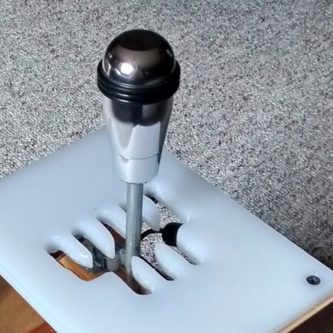
- 1 Polyethelene Cutting Board (8″ x 11″ x 0.5″ thick) – (This is for the shifter gate)
- 8 Micro switches (the “keys/buttons” for gears 1-7 plus reverse)
- Teensy 2.0 USB (what we use to interface with the PC)
- Mini USB cable to connect to PC (and possibly an ‘active’ USB extension cable)
- 3/8″ x 8″ bolt (thread pattern is 3/8 x16) or metric equivalent (~9mm x 20cm)
- A fairly stiff spring about 3″ long and wide enough for your bolt to fit through.
- Two cabinet clasps
- Two 1″ L brackets
- Drywall and/or wood screws
- Two machine screws with washers and lock nuts (screws should be roughly the same diameter as the holes in the L brackets, so it won’t rattle around).
- 20-22 gauge stranded wire (or smaller)
- Shift knob of your choice
Here are the tools you’ll need:
- Handsaw (if you have access to a miter saw, jigsaw, table saw, etc. it will make your life easier, but you can do it with a regular old handsaw)
- Philips head screwdriver (assuming all screws you use are philips)
- Drill (with various bits)
- Dremel
- Hot glue gun
- (Optional) router or drill press with small plunge bits (makes cutting the gear notches much easier)
- (Optional) file and/or rasp for notching wood below cabinet clasps
- Soldering iron with solder
- Wire cutters
- (Maybe) electrical tape
Some other things you’ll need:
- Time
- Motivation
- Determination
- Patience
- (Recommended) A patient and understanding spouse/significant other who won’t mind not seeing you for a few evenings…
- More time
- Soldering experience
- (Highly recommended) Fine motor skills
How it works
Interfacing with the PC is the most important part of this whole process. After all, we need to make sure we can actually change gears in the game. I’ve decided to use micro switches ($5 for a pack of 10 online) along with a “Teensy 2.0” USB device programmed to communicate with the PC. Some other DIY shifters utilize circuit boards from cheap USB gamepads. While these may work just fine, finding one that will be reliable and easy to work with can be a bit of a headache. I spent about $22 on my Teensy, and it was totally worth it, (also the most expensive component in the whole project)
Now, you may be thinking, “alright, the building portion I can handle, but I know nothing about this Teensy 2.0 device, and I certainly don’t know how to program it”. Never fear! I’ve already done the legwork for you on that side. Below, you’ll find the code to get yours functioning the way it needs to. I’ll also try to include a brief tutorial for actually getting that code loaded onto the Teensy (trying to make this as simple as possible for those who are intimidated by this kind of thing).
So let’s get into it.
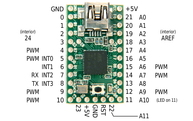
The “Teensy 2.0” is a USB controller chip with several “pins” (which, on my model, are tiny little conductive holes you solder your wires into) Among these is a ground “pin”, which is a common ground to be used with all other pins. More on that in a moment.
Here’s a picture of the Teensy 2.0:
I’ve programmed my “Teensy 2.0” to function like a PC keyboard, and assigned pins 0 through 7 to emulate pressing keyboard keys 0 through 7 respectively. Note, these are not the number pad keys, but the ones positioned above the letter keys. (you are free to modify my code to make these correspond to any keyboard key you like, just in case this conflicts with a key mapping you already use)
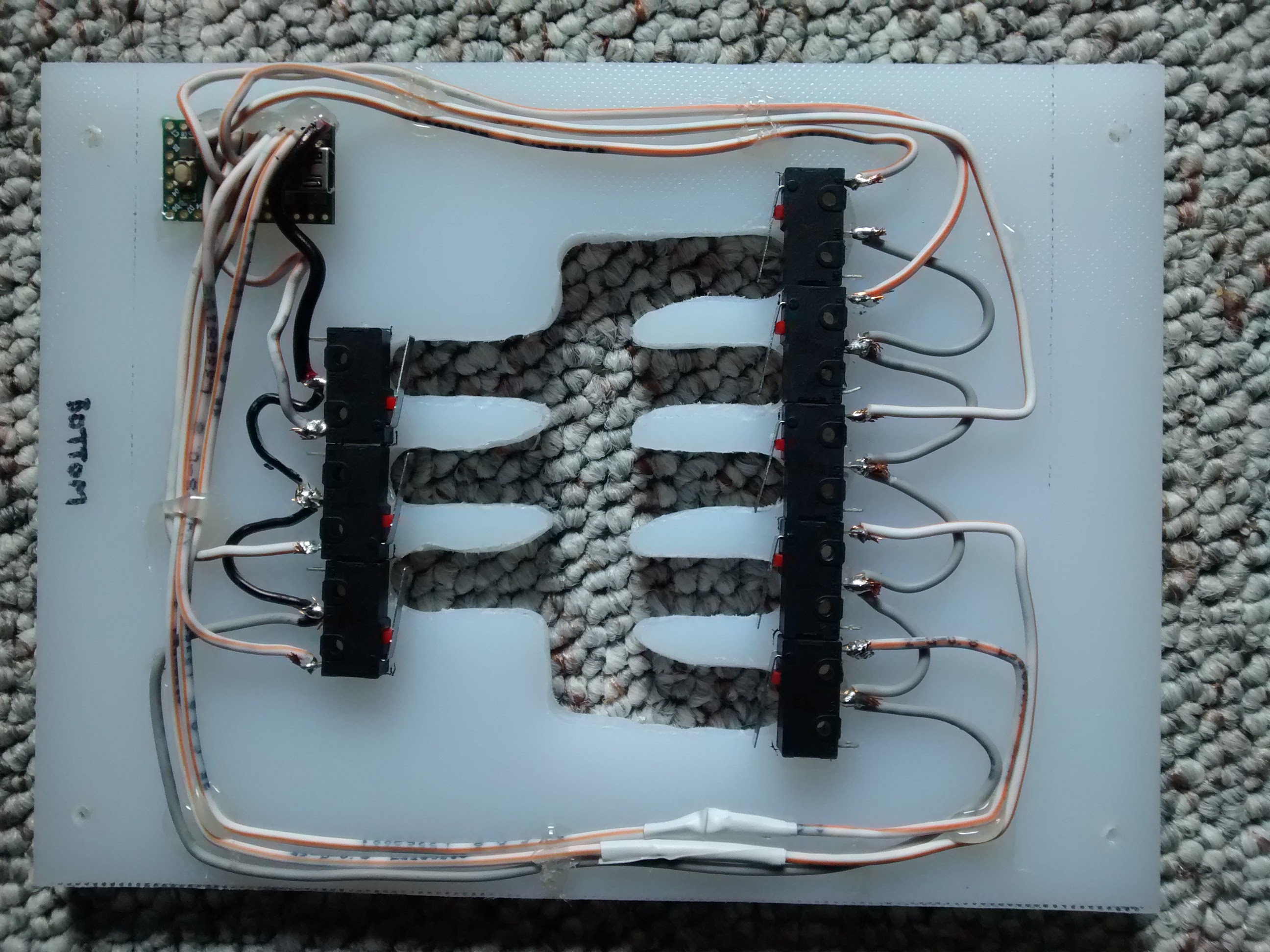
In the image below, you’ll see all the micro switches, which are wired back to the Teensy 2.0. The ground wire (in this case, the grey wire), is chained to each micro switch. When any of the micro switches, let’s say Gear 1, is pressed, it connects the ground wire to the “hot” wire, and makes a “key press.” Once the connection is terminated (let off the switch), the key is released. So again, you are making your PC think you are pressing and holding a keyboard key while the shifter is in each position. So that brings us to the next point.
You’ll need to map your individual gears to each appropriate number key (micro switch) within the game. NOTE: In this case (Dirt Rally), neutral is not a mapped key, and the game determines that if no gear is currently selected, then you must be in neutral, and so it shifts the car into neutral.
The Code
/* Buttons to USB Joystick Example
You must select Joystick from the “Tools > USB Type” menu
This example code is in the public domain.
*/
#include <Bounce2.h>
// Create Bounce objects for each button. The Bounce object
// automatically deals with contact chatter or “bounce”, and
// it makes detecting changes very simple.
Bounce button0 = Bounce(0, 10);
Bounce button1 = Bounce(1, 10); // 10 = 10 ms debounce time
Bounce button2 = Bounce(2, 10); // which is appropriate for
Bounce button3 = Bounce(3, 10); // most mechanical pushbuttons
Bounce button4 = Bounce(4, 10);
Bounce button5 = Bounce(5, 10);
Bounce button6 = Bounce(6, 10);
Bounce button7 = Bounce(7, 10);
Bounce button8 = Bounce(8, 10);
Bounce button9 = Bounce(9, 10);
void setup() {
// Configure the pins for input mode with pullup resistors.
// The pushbuttons connect from each pin to ground. When
// the button is pressed, the pin reads LOW because the button
// shorts it to ground. When released, the pin reads HIGH
// because the pullup resistor connects to +5 volts inside
// the chip. LOW for “on”, and HIGH for “off” may seem
// backwards, but using the on-chip pullup resistors is very
// convenient. The scheme is called “active low”, and it’s
// very commonly used in electronics… so much that the chip
// has built-in pullup resistors!
Joystick.X(512);
Joystick.Y(512);
Joystick.Z(512);
Joystick.Zrotate(512);
Joystick.sliderLeft(512);
Joystick.sliderRight(512);
Joystick.hat(-1);
pinMode(0, INPUT_PULLUP);
pinMode(1, INPUT_PULLUP);
pinMode(2, INPUT_PULLUP);
pinMode(3, INPUT_PULLUP);
pinMode(4, INPUT_PULLUP);
pinMode(5, INPUT_PULLUP);
pinMode(6, INPUT_PULLUP); // Teensy++ LED, may need 1k resistor pullup
pinMode(7, INPUT_PULLUP);
pinMode(8, INPUT_PULLUP);
pinMode(9, INPUT_PULLUP);
// Please be aware the X, Y, Z, Zr and Slider axes will have default
// settings, if you only use the buttons. This can give the appearance
// of the buttons interfering with the axes, if your PC software shows
// different default assumed values before your first button press.
// More details here:
// [link]
}
void loop() {
// Update all the buttons. There should not be any long
// delays in loop(), so this runs repetitively at a rate
// faster than the buttons could be pressed and released.
button0.update();
button1.update();
button2.update();
button3.update();
button4.update();
button5.update();
button6.update();
button7.update();
button8.update();
button9.update();
// Check each button for “falling” edge.
// Update the Joystick buttons only upon changes.
// falling = high (not pressed – voltage from pullup resistor)
// to low (pressed – button connects pin to ground)
if (button0.fallingEdge()) {
Joystick.button(1, 1);
}
if (button1.fallingEdge()) {
Joystick.button(2, 1);
}
if (button2.fallingEdge()) {
Joystick.button(3, 1);
}
if (button3.fallingEdge()) {
Joystick.button(4, 1);
}
if (button4.fallingEdge()) {
Joystick.button(5, 1);
}
if (button5.fallingEdge()) {
Joystick.button(6, 1);
}
if (button6.fallingEdge()) {
Joystick.button(7, 1);
}
if (button7.fallingEdge()) {
Joystick.button(8, 1);
}
if (button8.fallingEdge()) {
Joystick.button(9, 1);
}
if (button9.fallingEdge()) {
Joystick.button(10, 1);
}
// Check each button for “rising” edge
// Update the Joystick buttons only upon changes.
// rising = low (pressed – button connects pin to ground)
// to high (not pressed – voltage from pullup resistor)
if (button0.risingEdge()) {
Joystick.button(1, 0);
}
if (button1.risingEdge()) {
Joystick.button(2, 0);
}
if (button2.risingEdge()) {
Joystick.button(3, 0);
}
if (button3.risingEdge()) {
Joystick.button(4, 0);
}
if (button4.risingEdge()) {
Joystick.button(5, 0);
}
if (button5.risingEdge()) {
Joystick.button(6, 0);
}
if (button6.risingEdge()) {
Joystick.button(7, 0);
}
if (button7.risingEdge()) {
Joystick.button(8, 0);
}
if (button8.risingEdge()) {
Joystick.button(9, 0);
}
if (button9.risingEdge()) {
Joystick.button(10, 0);
}
}
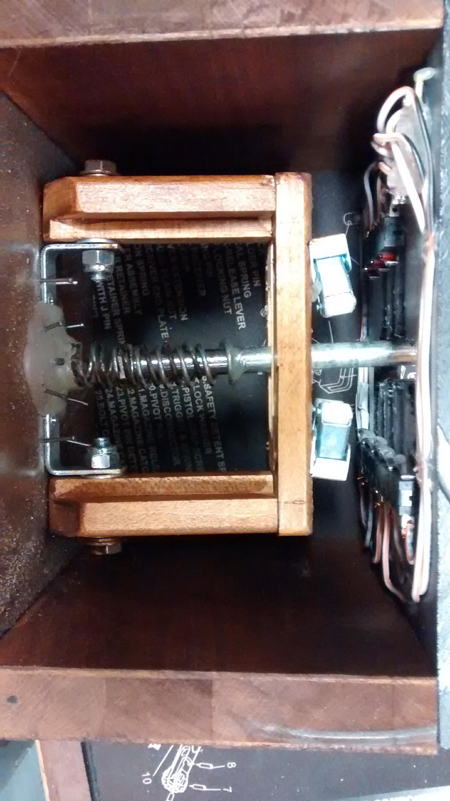
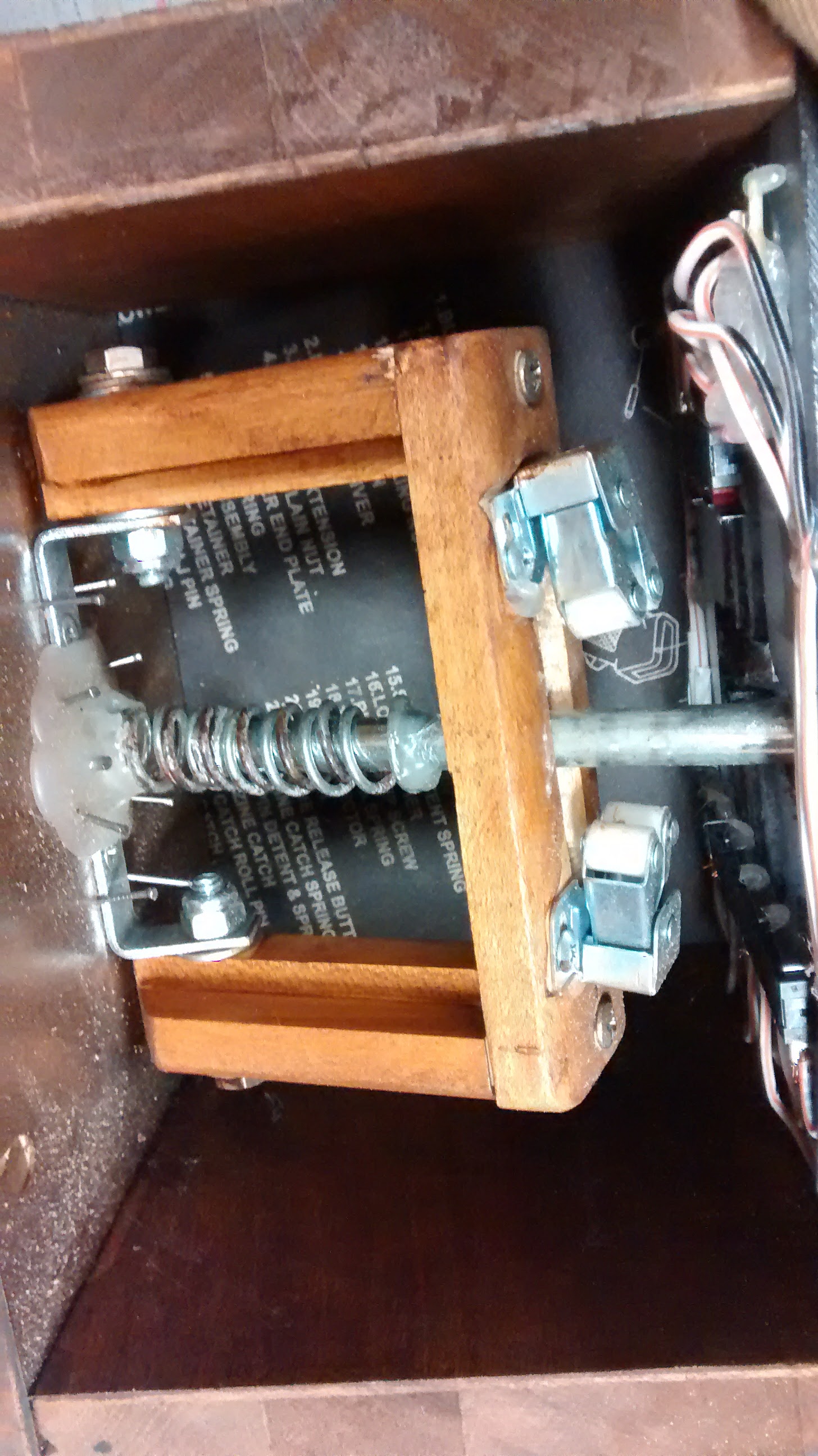
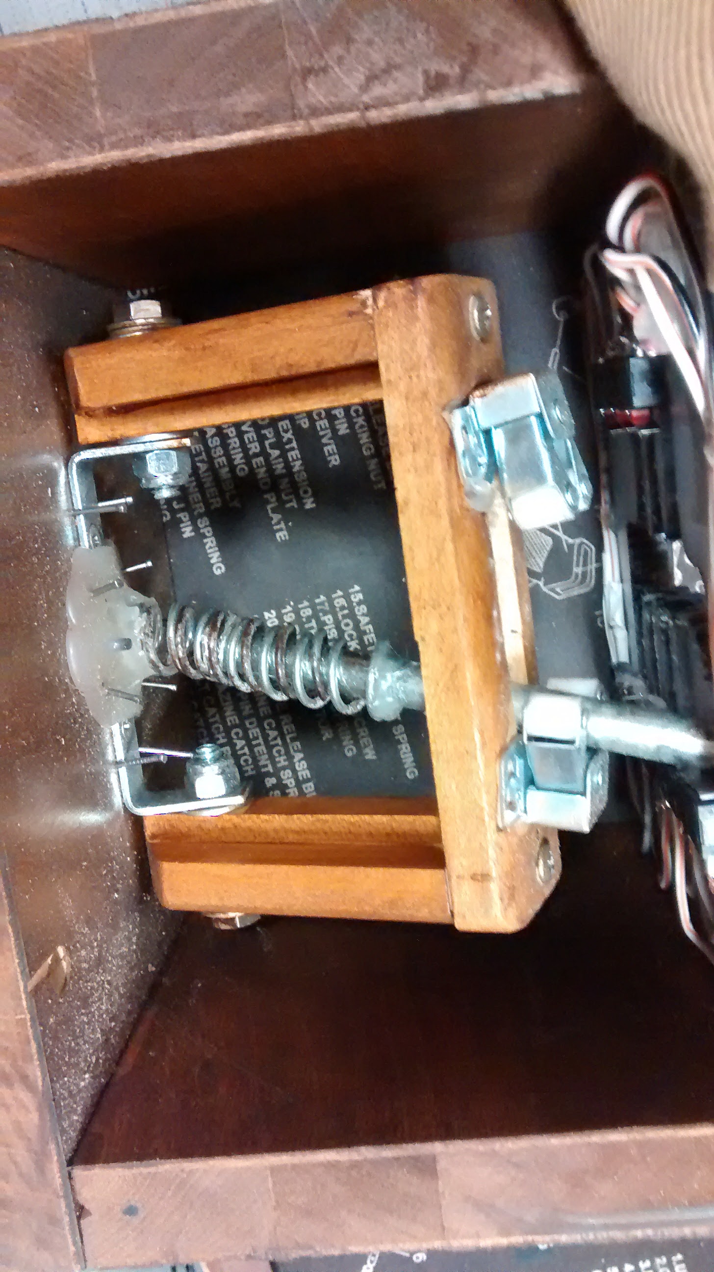
Additional Images
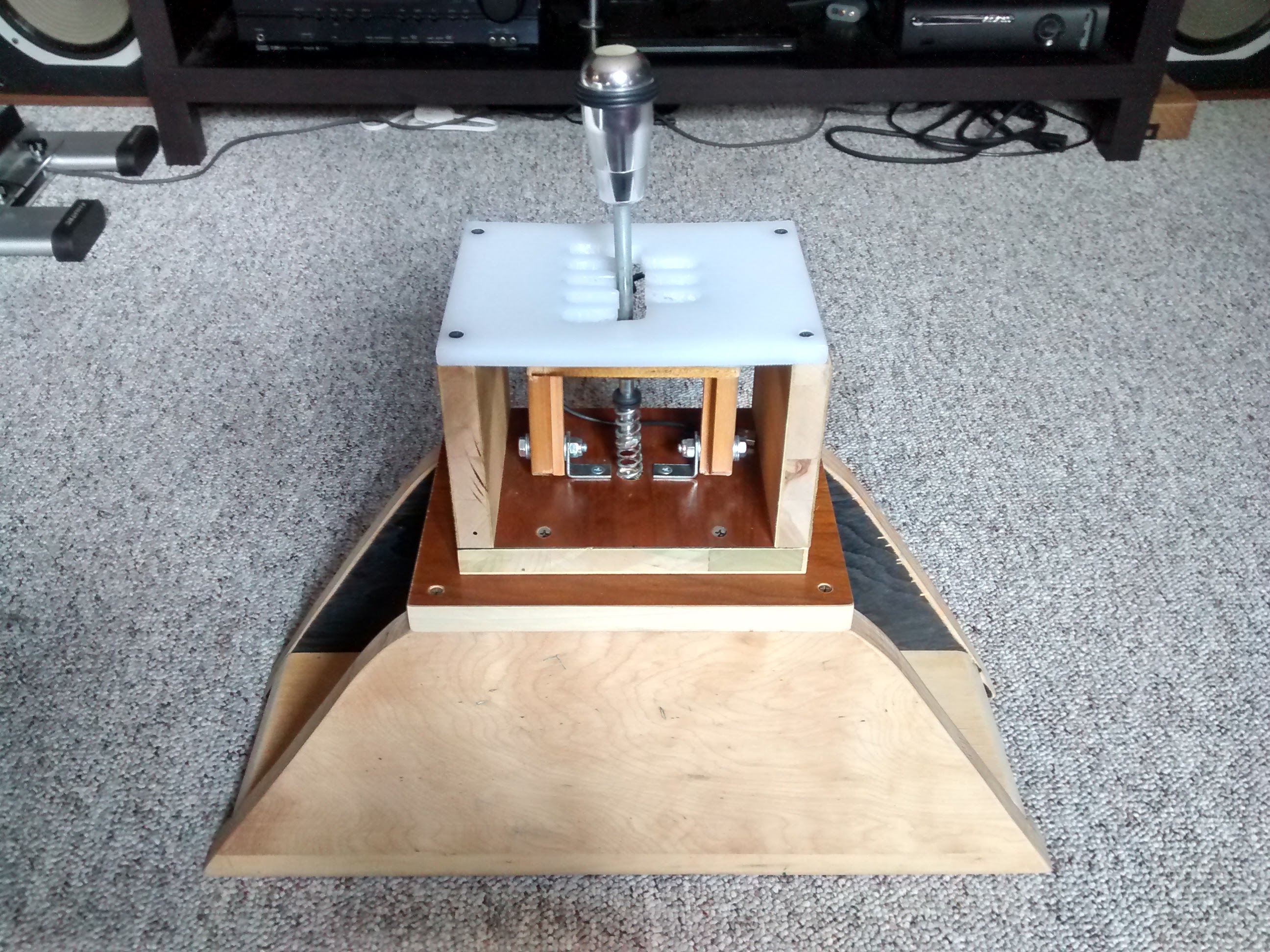
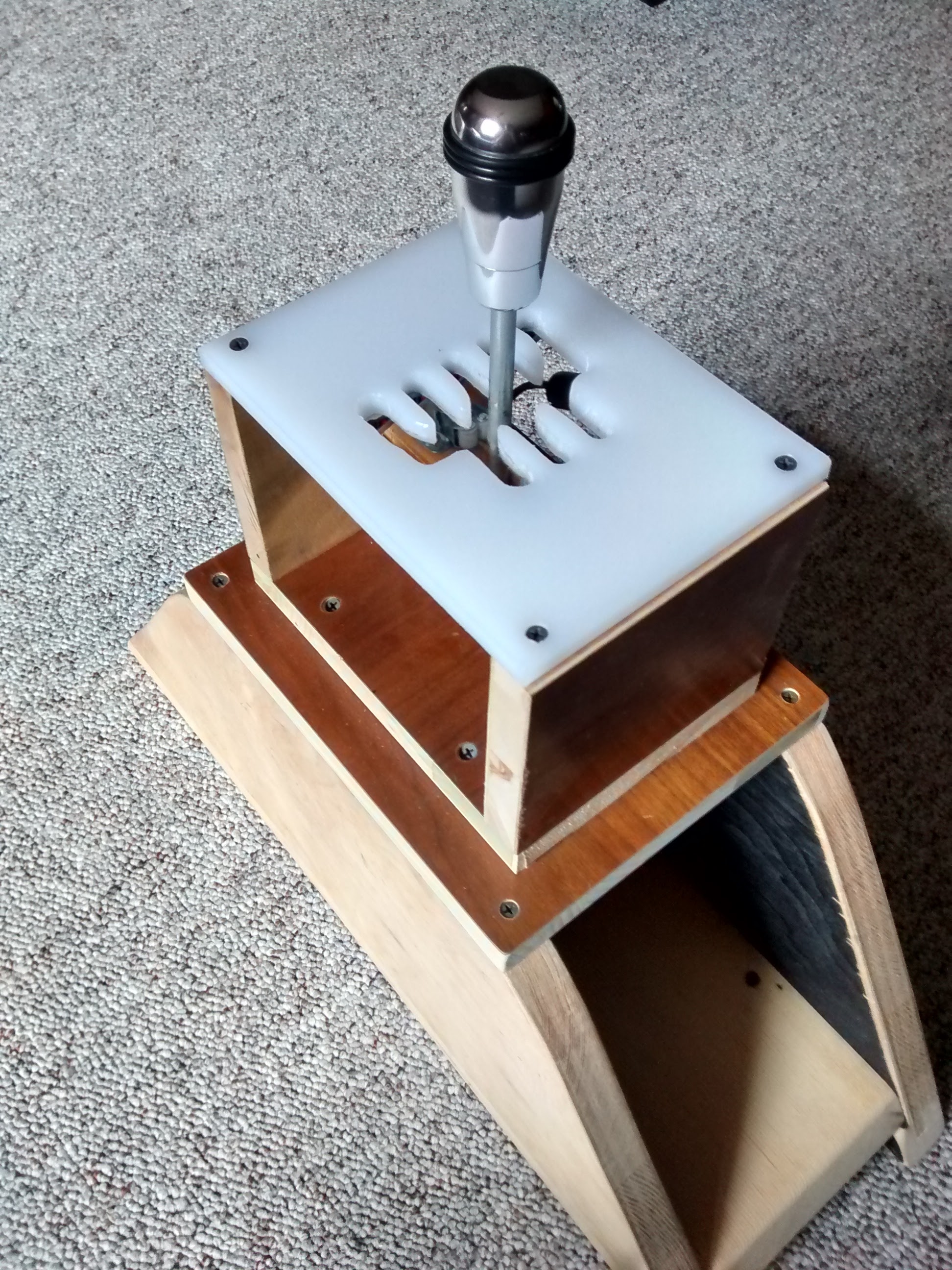
Here are some additional images of the shifter mechanism. Hopefully this will give help you with your construction.
Disclaimer: This design has given me problems not staying locked into place, yet being able to depress the switches reliably. It’s tricky to get the proper balance, and have the switches press reliably.
If I were to do it again, I would make the slot for the shifter a friction slot… enough to keep the rod in gear (switches pressed), and eliminate the issue with certain gears popping back into neutral. This would also require removing the main shifter spring, or finding one with extremely low tension.