
Overview
> Expect loading time due to the amount of images and videos !!Start update: Nov 19, 2015. 11.00 pm / 23.00 hrs Scroll down until you find your desired subject then click the chapter you want to studyChapter group content overview: Introductions All the basics needed for driving with steam locomotives All the signalling aspects that inhabits TS2015 All the extended driving skills Specified engines that needs special attention on driving Engine maintenance Practical issues Additional artistic issues Finally AppendixesNews about this guideThe coming of TS2016 brought some amazing lines and engines. The Riviëra Line for example with the King, Castle, Grange and the Pannier will be added to the chapters together with the German class 86. Beside that the Just Trains 5MT will be part of the new added chapters here in this guide.Other new chapers that are in prepararion:The BR-LNER J50The 2F Dock TankThe LMS 3F JintyThe GWR 4400 Small PrairiesThe ConsolidationOther new chapers will be:Driving with PZB / IndusiDriving with the vR E03, E10 and E40 Expert line during the steam eraGerman rolling Stock in the 60’s and 70’s The guide “Driving the steam locomotive and the technical aspects is now one of the greatest free educational resources ever brought online worldwide that combines practice skills live steaming and virtual driving together in one single guide. The guide contains 70 chapters and is based on the famous book “Leitfaden for der damfplokomotive” from “Niederstrasser”. and the German “Eisenbahn Lehrbucherei” The guide is enhanced with video’s, British footage resources and more.To create a better access in this guide the chapters will be grouped together. Each group contains the specific information according the group target.[/i]When a mistype had occurred please notify the mistype at [email protected] rephrasing the chapter and paragraph where the mistype has occurred. Then the correction will be made as well. If there is any supplementary or commentary please notify the writer and owner using [email protected] with an * is set for maintenance and major correction.Chapters with an ** endures maintenance and correction.Chapters with an *** are new chapters, which are in preparation and construction.Have a nice and educational study.
1.00 – Introduction

All issues about the introduction are mentioned in the chapters below.
1.01 – Preface
Based on experience and knowledge Mr. R.C. de Visser. Author from this guide and owner of Steamtrains Unlimited will now lift the secrets of driving and maintaining steam locomotives in all aspects of their preserved existence.
The guide as shown here contains actually 3 guides. The guides “Additional information of steam locomotives” and “The signal guide” were meant to be a stand alone guide in the workshop.
However the need to merge these guides into 1 guide was necessary keeping all information in this one single guide is rather required to drive within TS2015, MSTS and Trainz or other train simulators.
To aim the educational purposes and efforts in your hobby as an enhanced source of detailed technical knowledge and how to practice this knowledge as far as possible within and without TS2014 and other trainsimulators such as the old MSTS.
The information is even useful to practice in reality at a club or society on every working steam locomotive available. Wherever it is a steam powered N-Scale model locomotive, scale 1 engine, Minature Railway 7 1/4 inch or the original. with some interpretation you can do it all with this guide.[/h1][/b]

Steamtrains Unlimited exists since the coming of MSTS and was online as MSTS-Steamtrains. Some later the name changed into Steamtrains Unlimited aiming to promote the steam locomotive all over the world. To boost the hobbyist to become a member from a certain club or society preserving steam locomotives and even preserved a historic rail line and to keep the engines certified in running conditions for steam specials and additional purposes concerning rail travel.
This preface is now taken over some of the text which was meant to be in the brief introduction, but the amount of text was increasing and requires a separation of text into a new chapter. The index which is on the left is now better visible. In order to get the best out of this guide which now becomes more like an online e-book at this moment. More changes are going to take place in the near future to have the best advantage form this educational guide and e-book.
The upgrade was started in October and is now in a process of refining and correcting now.
Some educational issues and explanations have to be added still, but until so far, you already have a major study to devour.
Any mistyping or grammar violation will be solved during the refining period. Either the additional new chapters are at this moment in continuous review to eliminate errors as much as possible. However if you noticed a mistype or any text error, please notify the error at:

Steam in all its purity is the best natural power source there is, no other power source is stronger than steam.
Though the guide is since the upgrade finished, it is not fully complete at this moment. This means additional information is still brought in this guide. At this moment the guide contains over 65 chapters and is still expanding.
1.02 – The introduction of driving steam

Oktober 2014, After the coming of TS2015 and some major engines that has been brought out, an update of this guide was needed. Now educational video’s are added and some chapters needs to have some reviews as well in order to keep your performance updatet. Some articles has been added to have a better understanding of ongoing apects concerning the technics.
Is it handy to have TS2015 as a good basical educational study software prior to that proffesion?
Yes is it handy to have. It will introduce you into the world of modern train driving.
It will also introduce you into the world of the post steam era as well.
Some routes are usefull to get the understanding route knowledge and the basical things, but in practice the effort of TS will pay off and contribute to the job at the railroad compagny.
Take all the time to read this guide over and over again take your advantage on this knowledgements and yes this information is free. Get familiar with all equipment and drive your way around on steam trains.

Steam however is playing with thoughts and minds, even those who are not interested in trains at all will stay and watch a steam train passing by on steam specials. It is the way a steam train acts, reacts and works. It is a feeling of steam that keeps up mankind for continuing their motions and acts.
This brief manual will explain some major important issues you have to take care of before you even start to drive. All though this is a simulation you do not want to have a fatal blow back or a priming boiler. This will end your game as well and you can all start over again.
Lets hit the shovel and start to stoke and fire up this amazing wonder of technique. In order to drive a steam locomotive it is necessary to know the basics mathematics and techical aspects of steampower.
The guide is also usefull for MSTS. though check out the keyboard chart when you have not
reassign the key assigments in the MSTS game options. When you still use MSTS, you better reassign your keyboard. The left side of an USA standard keyboard (QWERTY) is suited for stoking purposes. The right side the nummeric keyboard is assigned for driving purposes.
The keyboard assignment option is a feature that is lacking in all releases from RS2012 until TS2015
Many drivers are switching to Automated Fireman because of the lack of knowledge, understanding and experiance of driving this amazing type of traction.
This is unadvisable except you are new to TS2015.
Newbie’s better start to drive in simple mode. Using simple mode will take care of all things newbie’s are unfaliliar with.
When you are new to TS2015, you better start in simple mode. Explore routes with a diesel or electric locomotive before you set of with steam anyway. Practicing steam driving needs a lot of skills, even is this simulator. This guide teach you how to drive and find the right balance between driving and stoking.
Take your position at the footplate of the engine and be prepared for your run. In this manual with pictures during a run or from real engines. All basics of driving a steam locomotive is mentioned. When you have tried it all properly and study all the material taking notice of all efforts you will have a major driving experiance. All mentioned issues are taken from Real-Time experiances and examples.
When you are member of a club or society concerning the restoration of steam locomotives, you then have a good and proper basic to move on. And of corse this is simulation, but the increasement of your knowledge will also increase the fun of this simulating enviroment.
First of all
In order to get the full advantage of manual driving you have to disable some features in the game option of TS2015
- Open TS2015 and go to the option screen
- Disable the automatic fireman by unticking the checkbox and clear the game cache.
- Restart TS2015, Choose your engine in a free roam environment or standard environment.
- Read carefully the next chapters and start practice all the mentioned methods and issues.
- Try to pick up the lessons in theis guide while running a steam train.
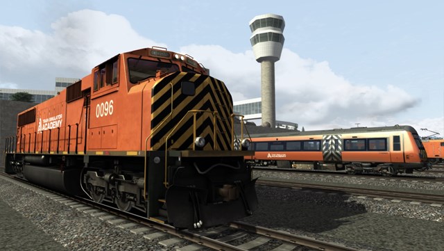
If you want to learn to drive, you better start with a diesel or electric in the Academy mode to get the best and proper understanding of driving a train. The Academy shows all basical aspects about diesel and electric engines and even the use of advanced driving methods and signalling issues.
The lessons thought concerning driving a steam locomotive by the academy are very basical and does not provide all the information, nor in simple mode, neither in advanced mode. You better do not rely on the Academy. There are quite some issues mentioned that does’t fit the real way of driving the steam locomotive.
You goal is to drive like an expert. This will improve your knowledge and skills and you are actually ready to become a real engine-driver after all.
then move on to Chapter 12 and read what is needed to get on that train, but……
Failed? Don’t worry just start over again.
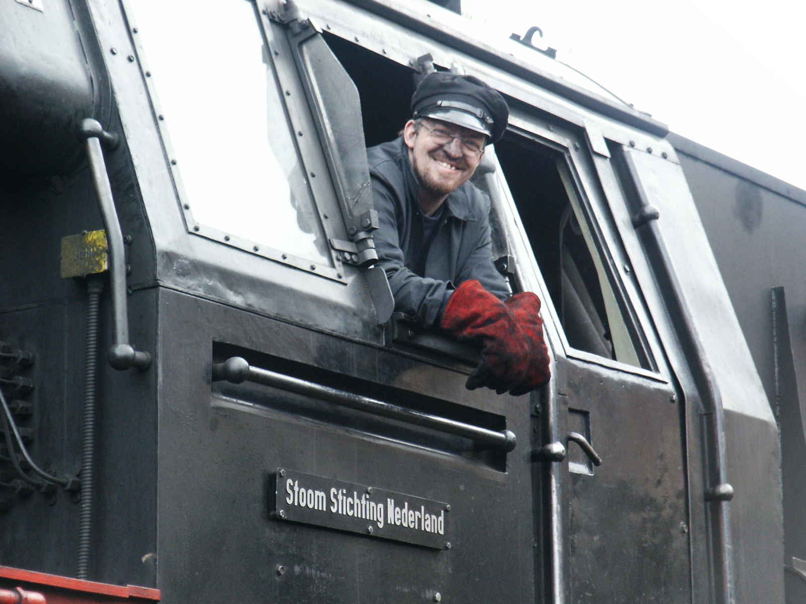
R.C. de Visser – Steamtrains unlimited
Facebook: www.facebook.com/steamtrainsunlimited
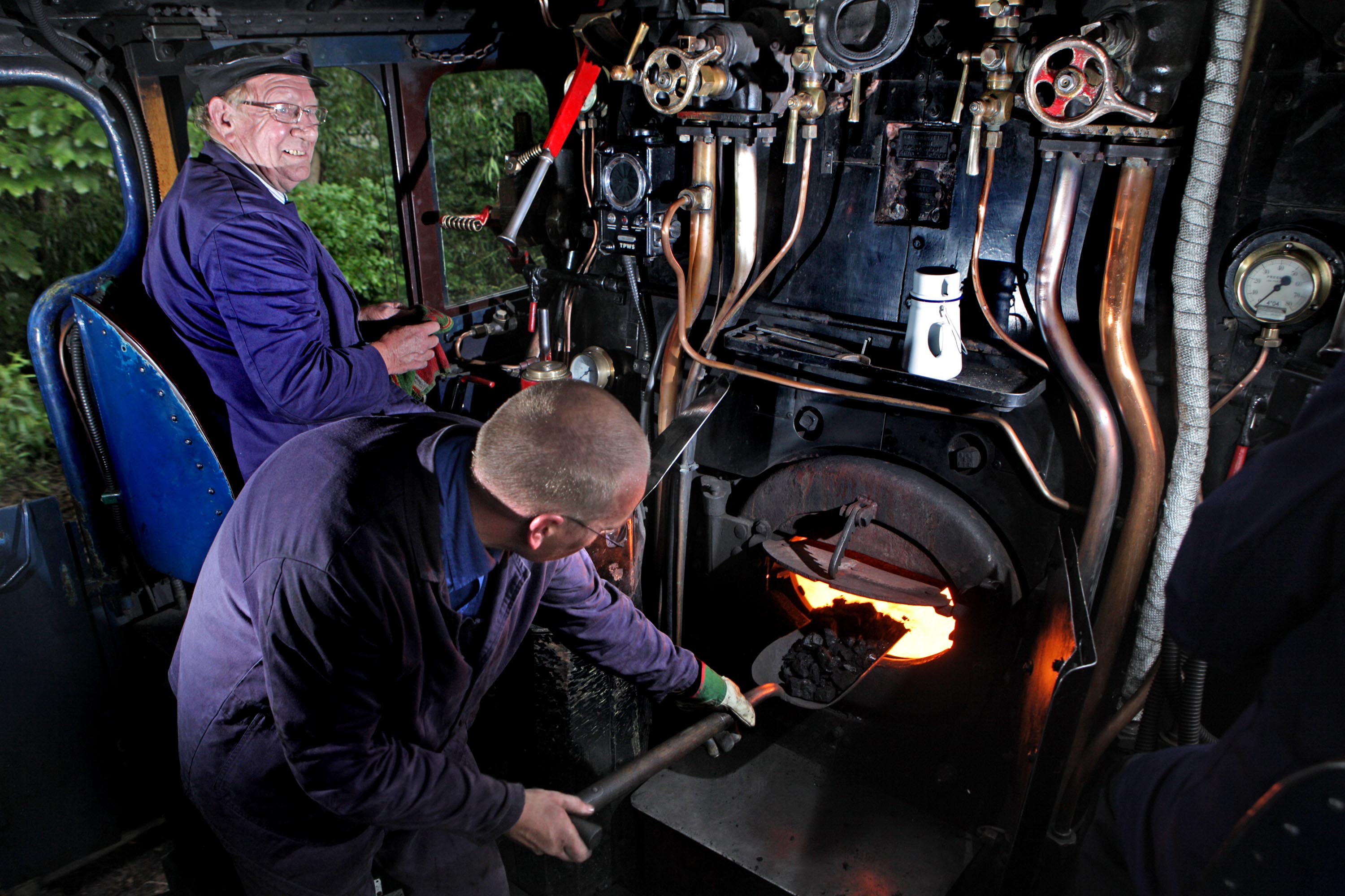
Mr. R.C. de Visser during a firemans shift on a open day at the depot in 2004

Copyrights:
All rights reserved by Steamtrains Unlimited – R.C. de Visser
The use of pictures, images, photo’s, graphics, drawings, diagrams, screenshots and video footages are permitted by restrictive conditions only: to present and show for educational purposes concerning this guide.
1.03 – Preparations to start
This Guide will reveal to you how to drive a steam locomotive as it should be. Let’s start to prepare ourselves before we pop off on any route with a steam locomotive. Check all wires and cables. the monitor(s) and PC(‘s). Make yourself comfortable.
When everything is set and you are well prepared now, then the time will come to drive. You have to get common with all the functions and knowledge, either with the route you drive you have to get familiar with.
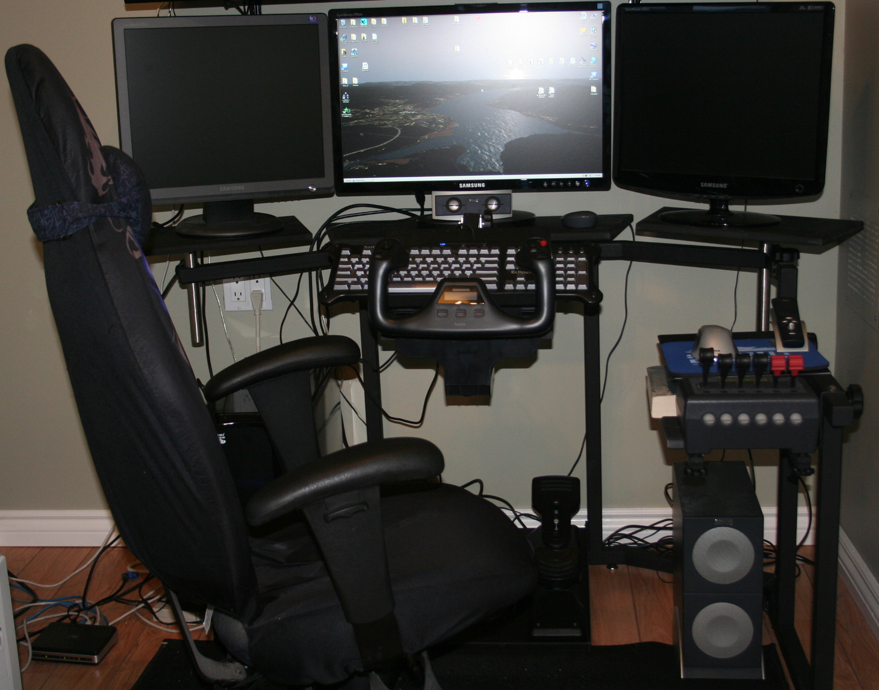
The shown configuration is even useful for TS2015 as well. Just change the flight yoke for a joystick and remap the functions to all controls needed and fitted for driving steam locomotives.
The use of an 2nd PC will either enhance the feeling of driving, it will provide additional information like track lay-outs, Time tables, track warrants, Track information sheets, train calculations, signal aspects and more. A good joystick mapper is available at digital transforms, for some money you have a great well working mapping utility which is only needed when the joystick supplier does not provide a mapping utility.
Equip your PC with levers, (rudder)pedals and joystick, map the axles of the levers, joystick and pedals to the desired keyboard combination. The pedals, throttle quadrant and joystick are often in use for Filght simulators, but mapping the keystrokes to the joystick will enhance and expand the feeling and freedom of real driving.
1.04 – Using a Joystick
TS2015 can be run with a Joystick as already noticed in chapter 3.1, Throttle and (rudder)pedals. It seems quite weird, but with some 3rd party software add-on’s you can easily activate a joystick, rudder pedals and throttle to your TS2015.

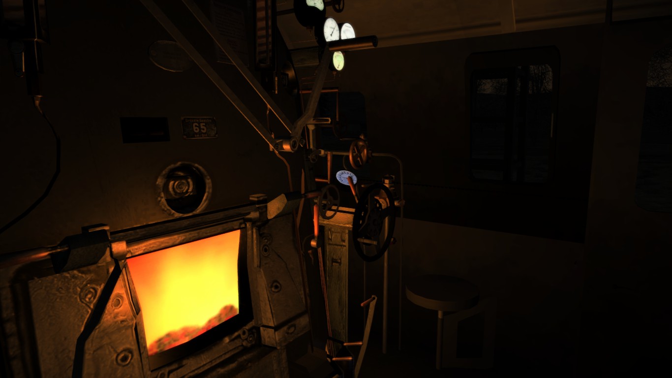
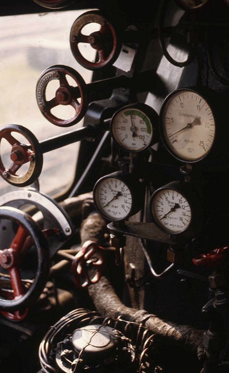
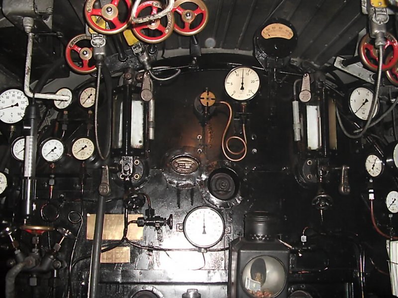
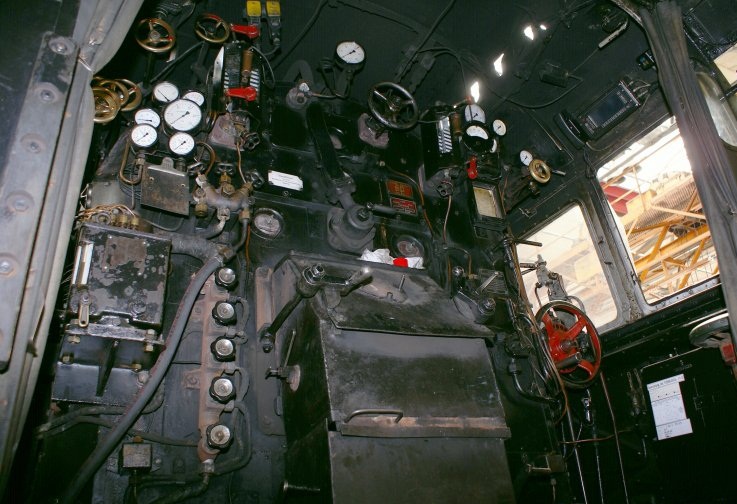
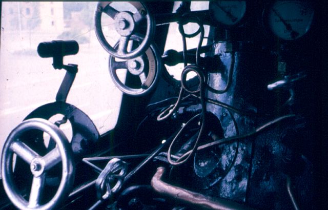
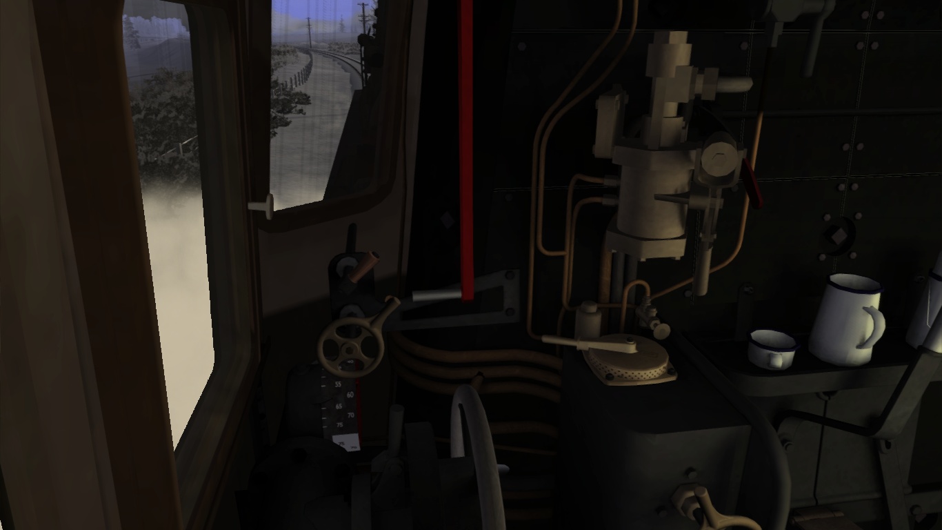
Try to make any connection with the footplate, levers, gauges, handlebars, reverser, regulator and indicators of a steam locomotive below.
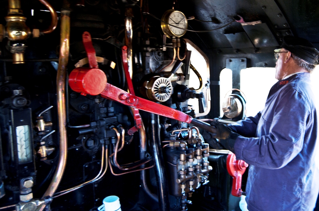
The Raildriver console suits diesel and electric locomotives, but the Raildriver console does not catch up with the footplate of a steam locomotive at all. The connection to a joystick is even better then the commonly known Rail Driver Console. However the Raildriver Console is an good solution for the use with any TS. Raildriver still lacks the steam locomotives features. Though Raildriver is programmable, the console itself is an off-spring from the Dash 8 console as you could compare both consoles.
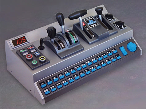
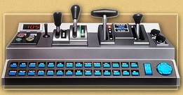
Some model railroad manufacturers has developed some amazing cab controllers suited for use with model trains. These controllers are quite expensive but it is well worth to have a short look on these cab controllers / consoles.
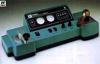

These controllers can be used for model railroading but these cabs should fit different DMU’s and EMU’s. Uhlenbrock created the hand wheel driven console which is quite suitable for diesel and electric loco’s like the locomotives made in the 50’s and 60’s
The joystick seems a simple device and either not comparable with a steam locomotive.
The truth is still different. The joystick can be programmed to fit the main controls. in extension an additional throttle and even pedals can be added to gain a full simulation experience.
On top of these extensions, a further enhancement of levers can be added. Saitek has a simple three lever console with three buttons that can be expanded with more lever sets combined with each other. On your imagination you van install a rack with 5, 6, 7 and even more sets together and assign every lever seperately from each other. Together with the joystick, throttle and (rudder) pedals you can achieve a tremendous feeling on driving a steam locomotive.


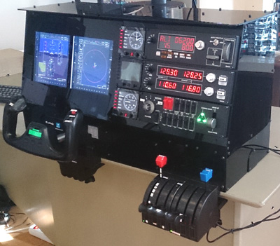


Passionated virtual pilots goes even beyond everybody’s imagination and install a cockpit in ther own house. Every device visible at the console, throttle quadrant, overhead panel, side panels is functional.
The levers are aimed for flightsimulation. Two, three or more lever consoles will boost the simulation experience. Each lever can be programmed separately using the programmable software as it comes with the levers. For Saitek the program is called SST Every lever block can be assigned to different operations. Together with a flight yoke of joystick set, you can now configure the controls according the engine you like to drive. If you are not able to get the Saitek levers or the SST program visit Digital Transforms and download Total Game Control. This tiny program allows you to map the joystick to operate the keystrokes. Total game Control is game independent, so it can be used for all Trainsims you have installed. Just create for every trainsim and either add-on engine a separate profile and.
Do not mix up keystrokes such as MSTS keystrokes with TS2015 otherwise you will have problems because Total Game control does not check the game in relation with the keystroke mapping. If you should use the D instead of A to open the regulator, you close the regulator instead of opening it. Though many key assignments are rather the same as in MSTS.
Based on a German engine with standard regulator and axles only. Buttons can be programmed as desired.
Configure the joystick at the LEFT side and the throttle at the RIGHT side, because the German regulator is left from the driver. The brakes are positioned at the right side next to the window. For left hand operated engines like British engines, just reconfigure the joystick, just mirror the positions to the other side except the forward and backward motions / operations.
The Keystroke mapping as follow:
2.00 – The basic of driving with steam
All issues from the cold start to the very end of the shift will be issued. It takes time to study all the efforts as notified in this basic guide.
All the instruments, equipment for as far as possible within the core limits of TS2015 are notified in the chapters below:
2.01 – How a steam locomotive works
Before you really start to study and practice the guide, take notice of this chapter first. It is going to tell you a brief overview of the working and technique of the steam locomotive. If you are ready with this chapter, you know some history the very basics of the steam locomotive.
One of the greatest inventions and discoveries in the world of today is the steam engine. A steam powered source was translated into a motional force able to do heave jobs. Famous names like
R. Stepheson, W. Murdock, E. Vivian, E. Murray, R. Trevitick and more. They all has contribute their inventions and developed a standard transport mass system in hauling freight that is spread world wide. It has an own infrastructure and it is capable to transport masses of freight and passengers.
You have probably watch the documentary about the history of the steam locomotive, the impact this invention had in the modern world. The industrial and economical boost what took place after this great invention. Especially the steam engine in particular has brought a tremendous effort and made the horse powered wagons to haul coal cost effective. And now you are a part of this invention. Trying to make yourself comfortable with a steam locomotive, hoping to understand the working of an engine and the equipment. However this chapter reveals only the brief history and the brief explanation of the very basic principles of the steam locomotive.
It is simple to create steam, the use of steam ws already discovered by the Romans.
They put water into a sphere with nozzles aimed in one direction. When the water was heated up by a heat source the water started to boil producing steam. That steam was blown out of the nozzles and the sphere started to turn around. The Roman emperors were afraid that this would result in the industrialisation of production. The emperors should have to release the slaves, and lost their investments in the “deals” with slave traders.
However the steam engine was born. but the development was stored away for a long time and after the end of the middle ages, at the start of the 19th century, industrialisation kicks in and the need for speeding up production lines was required. Increasing the production lines means more rough materials, liquids, pre-prepared products were needed, but the transport system was not suited to transport large quantities so a solution was desperately needed. R. Trevitick developed an engine that was able to haul a certain amount of wagons along a rail that could carry freight, more freight than by vessel or a horse powered lorry. That engine was the steam locomotive the Trevitick Coalbrookdale locomotive and was the first step in railway developing.
Based on the Roman concept, the steam locomotive works pretty much the same.
The sphere became a boiler that was heated up causing the water to boil and evaporated into steam. Steam is a gas that could be compressed. Compressed steam becomes pressurized and was powerful enough to blow something away. This force is now ready to use as power supply.
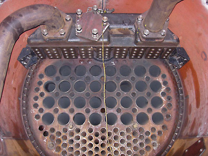
The boiler was developed and in the development the engineers discovered that a horizontal boiler could contain much more steam power instead of a vertical boiler. in the boiler many tubes and pipes were installed for the most economical method of heat exchange to the water.
The boiler now could stand more pressure and was quite easy to install on a frame that was supplied with wheels or even static in a power house.
Steam was produced and transported through a pipe to a engine that translate steam force using a cylinder that contains a cylinder head mounted to a piston. The steam pressure “blows’ the cylinder head with piston into one direction. On top of that cylinder a steam divider was installed. to divides the steam on exact the right moment to the other side of the cylinder head resulting the cylinder head with piston to be “blown” back. Again the diver changes direction and the whole sequence starts all over again.
The switch between either direction was operated by a valve spindle and a set of bars and pistons that was empowered by the cylinder piston itself
The cylinder piston is fit to a hinge that is installed on a slider bearer that fits a slider bar.
This is know as the cross head. From out of the cross head, a connecting rod is liked between the sliding section and a wheel tap. The wheel tap is placed out of the center axle.
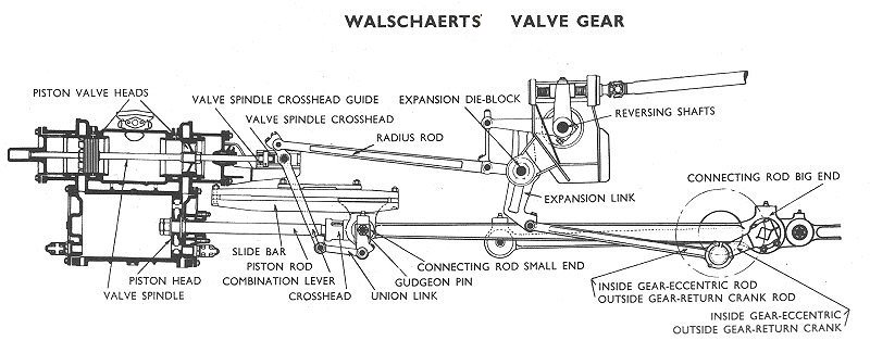
When the cylinder starts to move on and back the motion and force was exchanged to the wheel tap, causing the wheel to revolute around on the axle of the wheel.
More wheels were coupled by coupler rods on the same principle as the main driving wheel.
This resulted in a boosted force on the wheels creating an hugh amount of force that was able to haul heavy freight. This force is exchanged to the coupler and the motion that is generated by the steam power and the force of gravity that create adhesive traction between the rail surface and the revolution driving wheels of the engine. The trick now is to start to move the train without spinning or slipping wheels of the engine, if the wheels does not slip or spin, you have overcome the massive weight of the train. When the train is moving. kinetic energy is absorbed in the weight of the train and will cause the train to roll on after the cut-off the regulator, reverser and either the use of the brake as well.

To maintain and drive a steam locomotive requires a lot of blood, sweat and tears.
Driver and fireman kept up the pressure, It was a mental heavy stressful duty railroad man has to achieve. A fire man was shovelling 2000 lbs. of coal at 50 km / 35 mile. When the engine is stationary. all motional rods, bars, levers, pistons, axles and more needed to be lubricated.
This has to be done in between two runs or shifts.
They always worked together as a team., the fireman was subject to the driver and was the drivers student. The driver was responsible for the proper education the fireman had to learn. After a several years the fireman became a driver and a fresh fireman was dispatched to the new driver.
Is this virtual footplate comparable with the original footplate? Yes and No.
Yes, because you will learn the most basical aspects you have to deal with including the signal aspects and theoretical aspects. when you in a run for about 60 minutes an a derailment occurs. you will become set up and irritated as well. Because you now can start over again
But it tells you exactly what (not) to do next time. You taste the thrill, the dream, the desire, the imagination, the sounds, the visible behaviours and the small feeling.
No, because the lack of the rough works, the ambience, the smell, the dirty hands and faces, the sizzling steam leaks, the feeling, pain and the passion.

2.02 – The start of your shift
In every branch, work, office, shop or even in private life, paperwork is always part of the daily life. It documents all information you have to deal with. The railroad companies does have an hugh amount of documents you need to know prior to the start of your shift and even prior to the start of your work. Underneath there is a certain amount of issues you need to know. Even in TS2015 you better document all of the route, engines and trains you are going to drive.

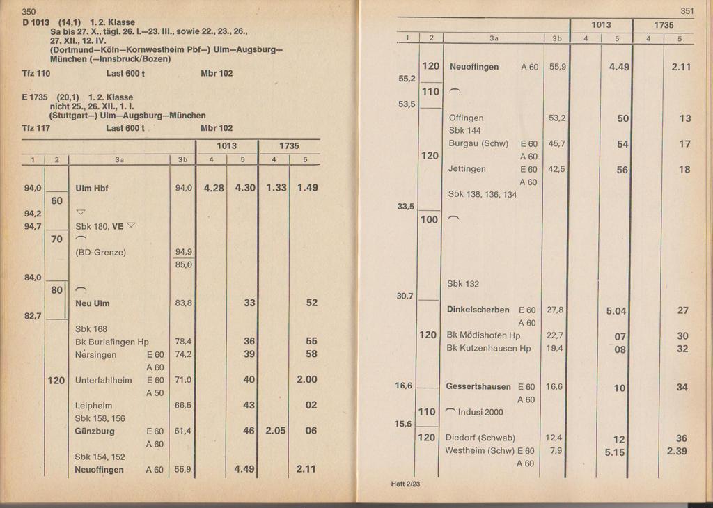
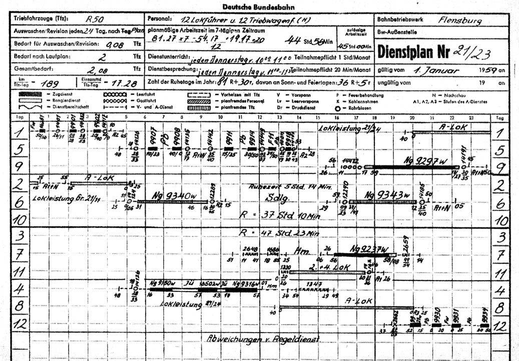
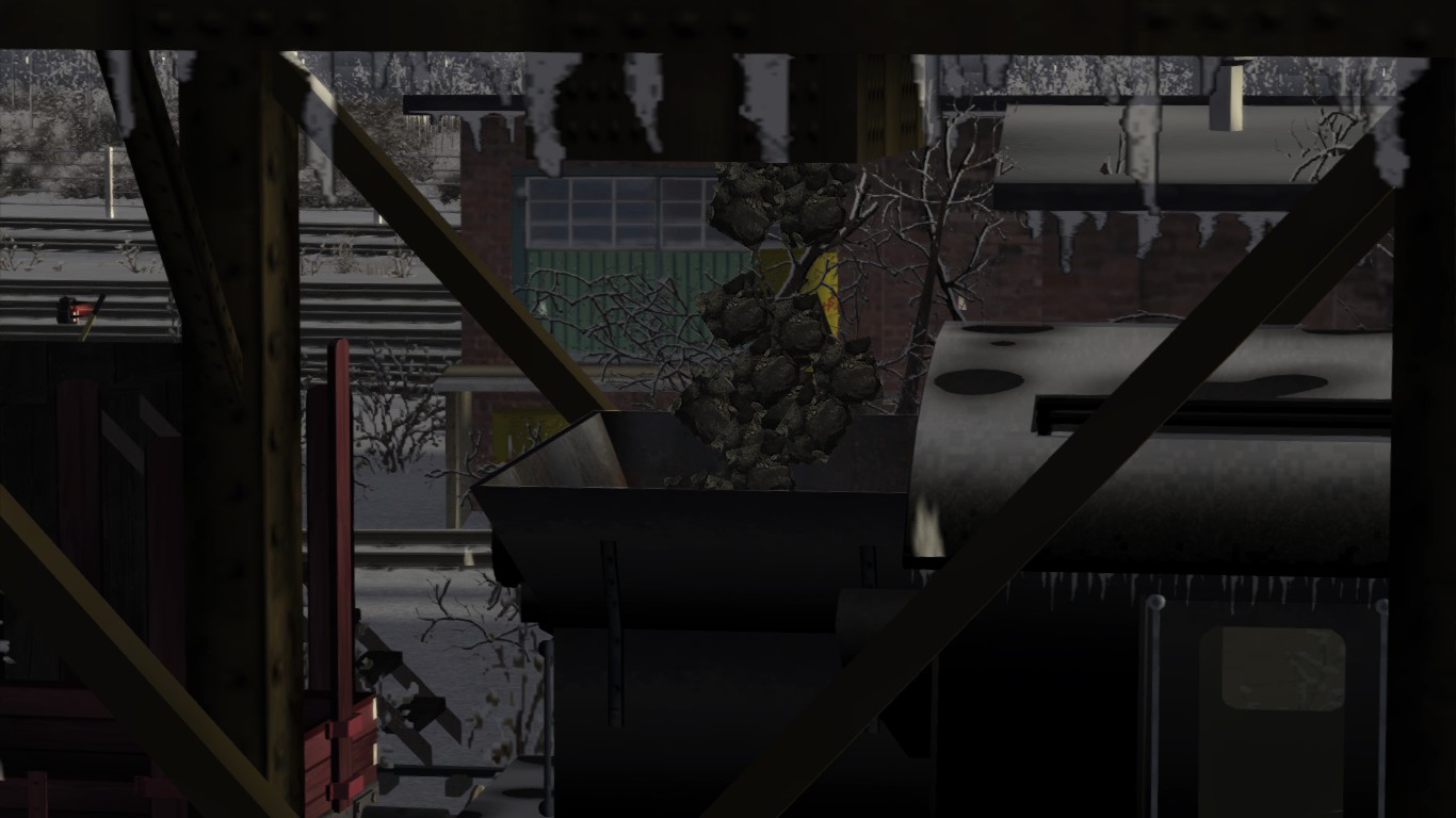
An original German Buchfarhplan. German Railroads uses original but edited “Buchfahrplans” (Trip Notebook) for all their routes available for MSTS. Put this “Buchfahrplan” at the easel and you have direct access at the “Buchfahrplan” during your run.
If any information available print it out and put information into binders for direct access when running a scenario. You can also use a 2nd PC or laptop containing digital documented information such as PDF or DOC (or other file formats) as long as you are able to access this information necessary for your run or scenario.

First of all, when arriving at the depot to start your shift, you report yourself at the dispatchers desk. In the case of TS2015 you choose your “job” to drive.
After making your coffee and receiving all equipment you now set of to your engine for preparation.
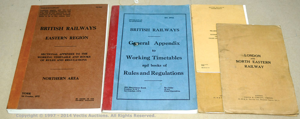
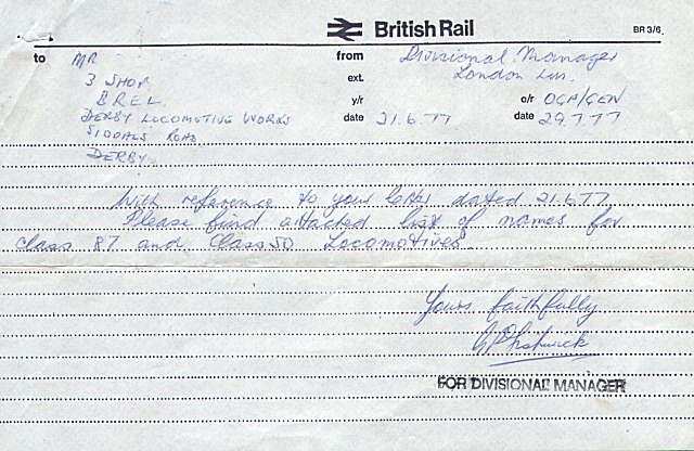
Trip notice booklets carries the time schedule of specific engines that are dispatched to a specified service. The service number at BR is often the same number as the headcode that you need to use on your engine when you are driving a diesel or electric engine. A steam locomotive needs to set the lamp code properly. Later on headcodes were put at the smokebox door.
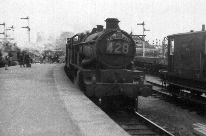
The trip notice shows the specific time table that is set for the mentioned shift. In the trip notification the headcodes can change, but the shift code remains the same.

Each region has their own set of trip notice booklets that contains all the schedules time tables. Often more booklets are in use depending the types and classes of trains.
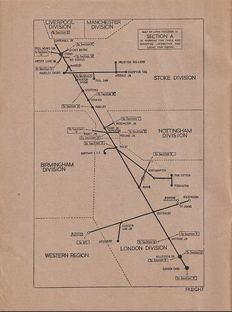
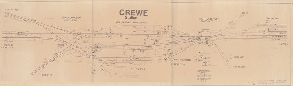
Each trip notice booklet contains a set of charts showing a global route lay-out of the specified region and specified the track lay-outs of each station, junction, yard, workshop or depot that is situated in that specified region. These lay-outs contains information about track length, signalling issues, catch points and more which is valid every track separately.
A marshal list is almost equal to the trip notice. However a marshal list mostly is valid for one day. TS2015 has an option to use a Marshal list when creating a scenario. When the scenario is running the marshal list can be overviewed by pressing [ F1 ] and appears at the left fly out.
Some scenario’s contains a additional file to print the list to recreate the reality more closely.


A marshal list is created with a type writer and can be edited by hand by the signaller or dispatcher. When a change is made the driver himself will made changes to the marshal list.
Next: An example of a written train order that contains all information that affects your run of shift. Last: The shunt list tat contains all information concerning all shunting trains, empty stocks, parcel trains, etc, etc.
After entering the office and you have take notice of all works for that day to take place you just take notice of every memo that is in execution and possible will affect your shift as well. Getting this information is always a part at every shift no matter the day of type of train you drive.
The dispatcher and can also hand out a special order for you that will completely change your expected shift as well.
The dispatcher keeps record of your progress. This means track acknowledgement, medical history, licensing, hours of working, day offs, holidays and other personal issues of your concern.
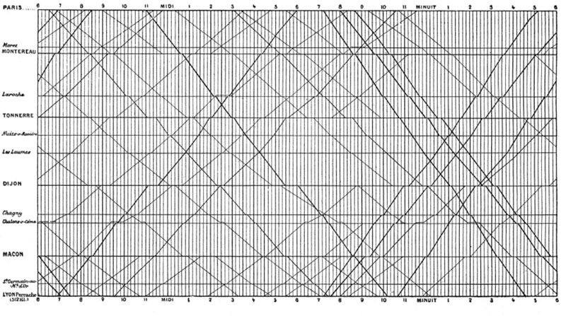
Dispatchers, signallers and time table developers will work with these diagrams. The diagram shows a combination of time / route and station. Each station is mentioned at the left in sequence of the route. while the time line goes from left to right. The angled lines shows the path a train is running and shows speed. time and endurance of that particular train.
The dispatcher also memorize every change into a record that is kept in the depot office about every driver and fireman and other employees.
An employee record
When you have take notice of all of your shift, train notifications and additional reports that is valid for the route, train and stations you have to encounter you set of for your engine to prepare the engine.
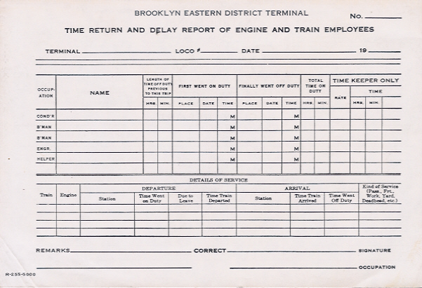
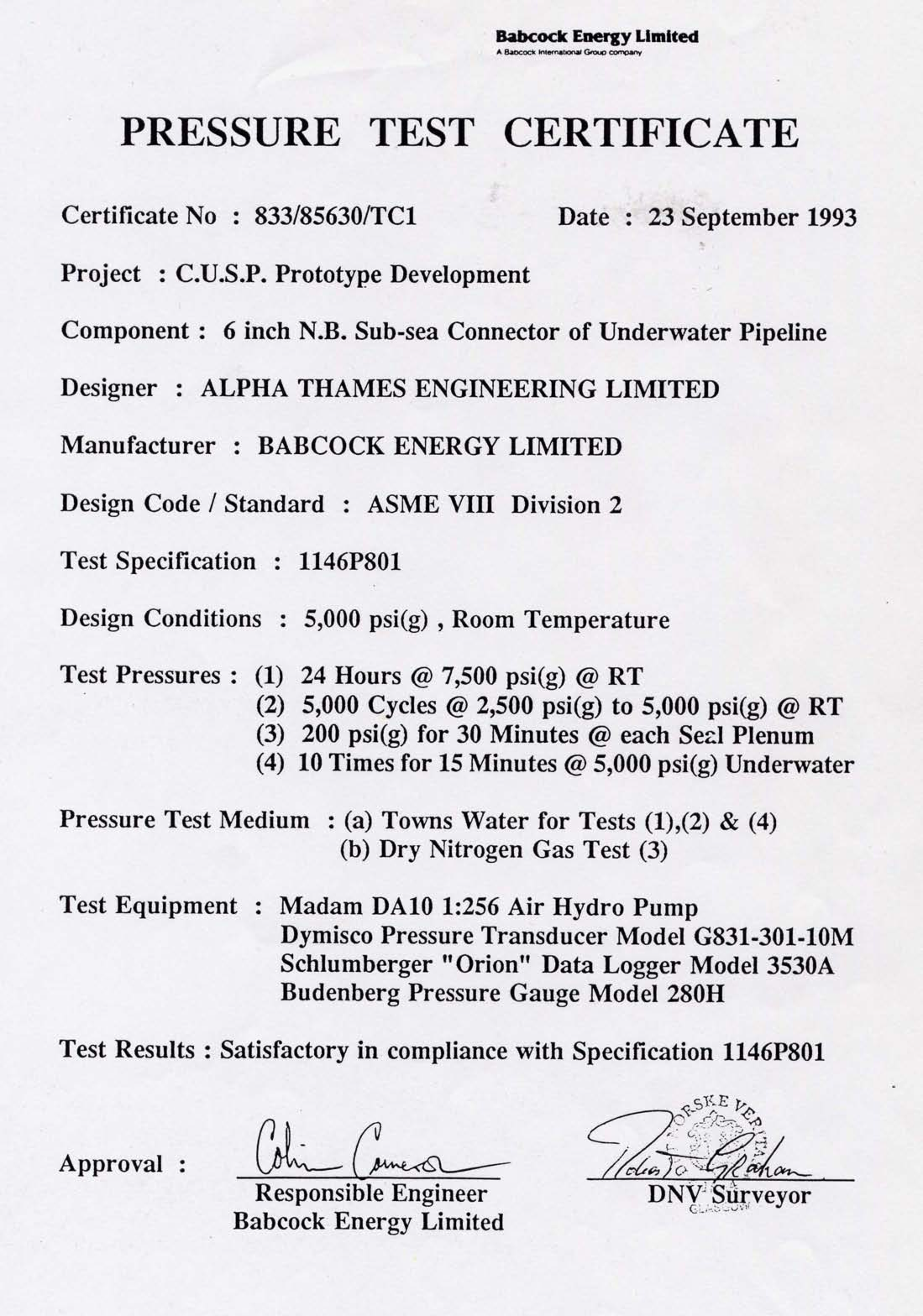
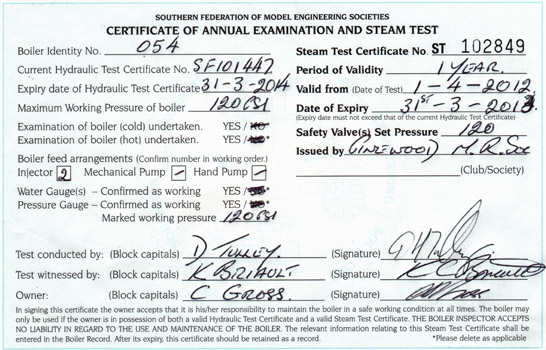
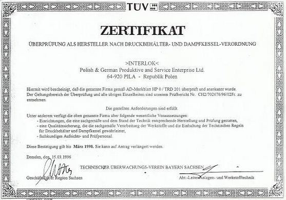
Every engine got a logbook and all the certificates of all pressurized equipment and boiler certificate. This logbook needs to be filled out after every run that records every discrepancy and aberrance you encounter during the run. This logbook is always given to the dispatcher or to the crew that takes over the engine during a run.
The engines certifications and documents are mostly stored at the depot where the engine is located. Binders contains all documents for each engine specifically.
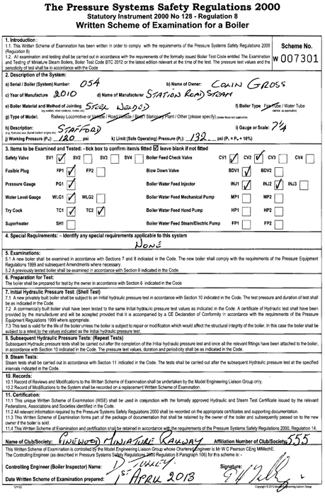

Boiler certificates and certificates that guarantee the state has the keyrole for the use of an engine to enshure the safety of driving and pressurisation of the boiler itself. The approval of a boiler is executed by govermental departments and is part of the national safety regulations which is common for every country running a railway company.
2.03 – Preparations to fire up and igniting the fire.
203 Preparations to fire up and igniting the fire
Before you create the fire you need to know the different types of steam. Every type of steam got its own specifics. Depending the type of locomotive you use will also depend the type of steam you need.

Wet steam is the most common form of steam actually experienced by almost all flora. When steam is generated using a boiler, it usually contains wetness from non-vaporized water molecules that are carried over into the distributed steam. Even the best boilers may discharge steam containing 3% to 5% wetness. As the water approaches the saturation state and begins to vaporize, some water, usually in the form of mist or droplets, is entrained in the rising steam and distributed downstream. This is one of the key reasons why separation is used to expell condense from distributed steam.

Saturated steam is actually dry steam which occurs when water is heated to the boiling point (sensible heating) and then vaporized with additional heat (latent heating). If this steam is then further heated above the saturation point, it becomes superheated steam (sensible heating).
Saturated Steam (Dry). Saturated steam however occurs at temperatures and pressures where steam (gas) and water (liquid) can coexist. In other words, it occurs when the rate of water vaporization is equal to the rate of condensation.
Advantages of using saturated steam for heating has quite a number of properties that make saturated steam an excellent heat source, particularly at temperatures of 100 °C (+/- 200°F) and higher.
Superheated steam is created by further heating wet or saturated steam beyond the saturated steam point using super heater elements mounted in the boiler tubes. This yields steam that has a higher temperature and lower density than saturated steam at the same pressure. Superheated steam is mainly used in propulsion/drive applications such as turbines, and is not typically used for heat transfer applications.
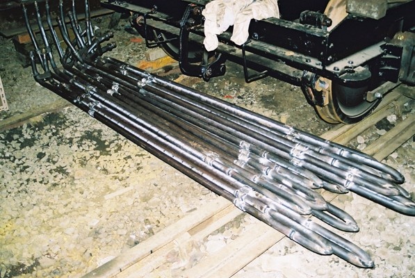
Newly constructed super heater elements ready to install.
It is advantageous to both supply and discharge the steam while in the superheated state because condensate will be generated inside steam-driven equipment during normal operation, minimizing the risk of damage from erosion or carbonic acid corrosion. In addition, as the theoretical thermal efficiency of the turbine is calculated from the value of the enthalpy at the turbine inlet and outlet, increasing the degree of superheating as well as the pressure raises the enthalpy at the turbine inlet side, and is thereby effective at improving thermal efficiency.
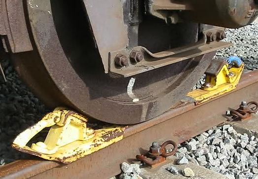
After you arrive at your engine, you start to walk around the engine and check all pistons, rods, hoses, wheels, cylinders, etc. When you take over the engine at a station mention train movements aside your engine. Check also if the rail shoes are in position at both sides of a set of wheels.
Get into the engine by pressing [ 2 ] and press the [ / ] Button to set the handbrake.
The hand brake of a Just Trains 4MT and the hand brake of a Black 5 (Port Road).
At some advanced engines such as the Just Trains 4MT and 6MT you see the lever spinning when pressing the [ / ] button.
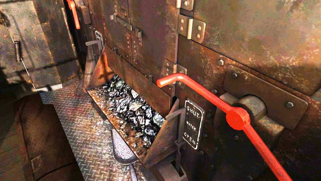
Preparing a steam locomotive in cold state takes a lot of time. First of all take away the chimney cover or chimney lid and close all valves to keep the pressure when the pressure starts to rise. Prior to firing up you test the water level and the water scope if these instruments are working properly. This is a major task with highest priority prior to firing up. An empty boiler causes an boiler explosion which is mentioned later on in this guide.
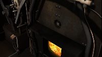
After you have done this test and water is surely in the boiler at the right level you are now ready to check the fire box. with a light you watch and inspect the fire grate closely if all bars of the fire grate are properly installed in place.

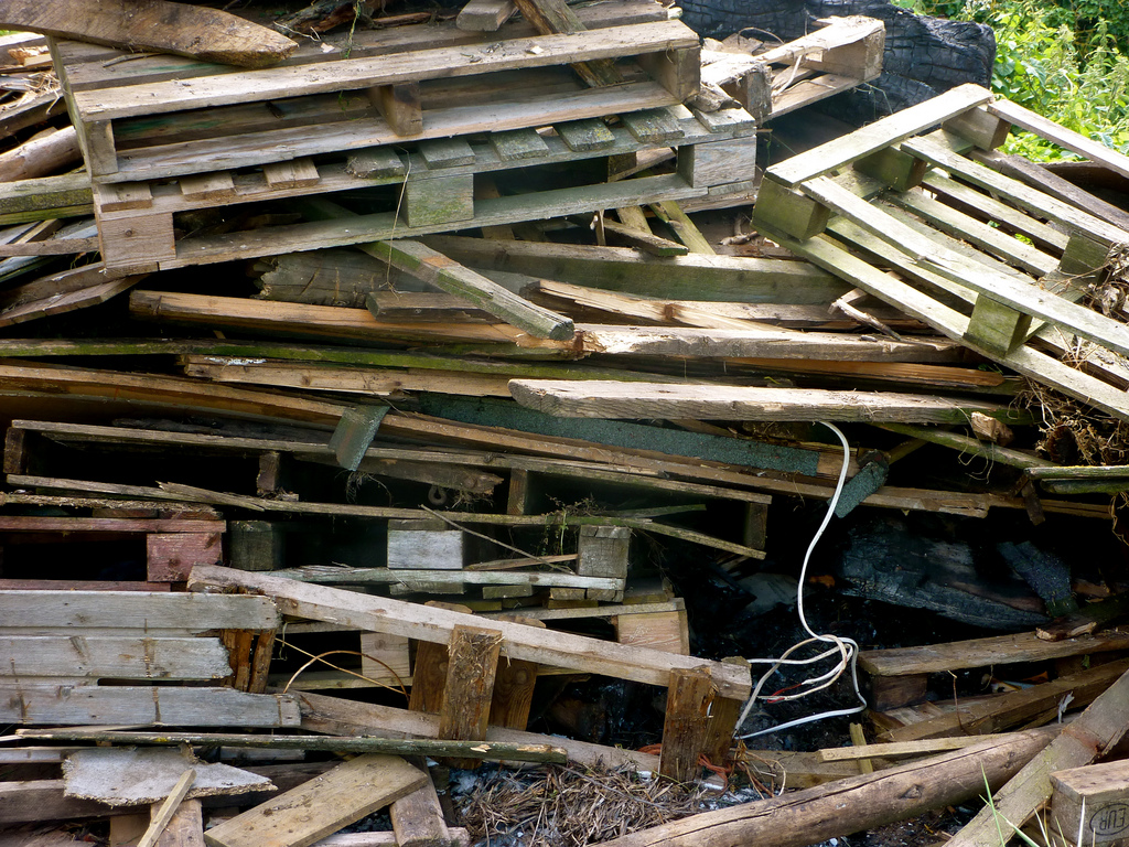
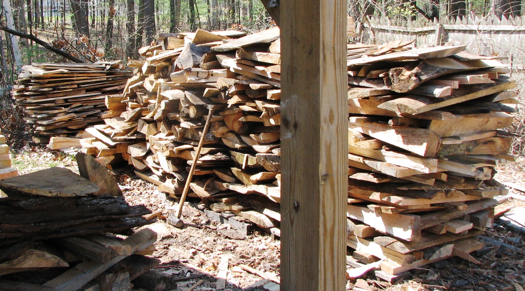
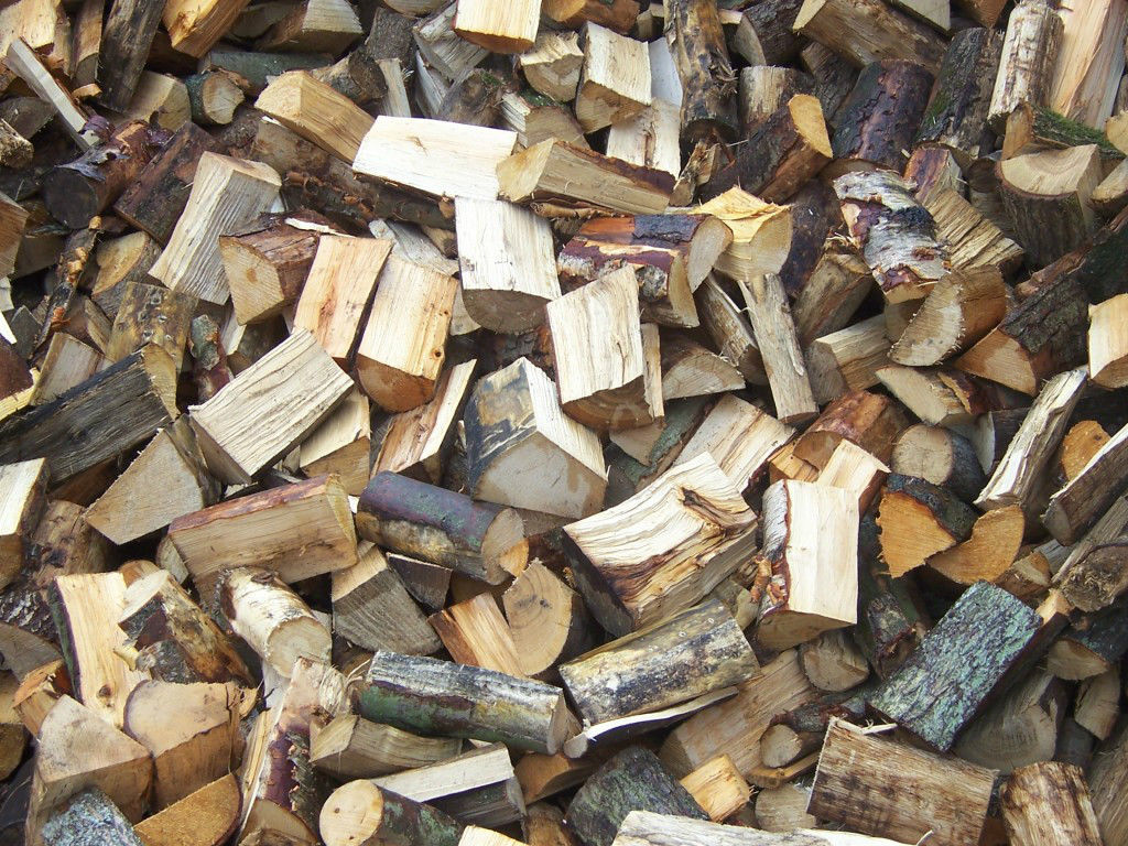
Then you build a pile of wood all over the fire grate using old sowed pallets and old timbres that are easily to handle.
- After the fire box is filled up with these bricks of scattered pallet wood, you now take a bucked of gasoline and some old shreds.
- You now put these shreds in the bucked of gasoline and submerge these shreds completely in the bucked of gasoline. Be sure these shreds are drowned with gasoline.
- Take the drowned shreds and wrap these shreds at some sticks or timbres of wood.
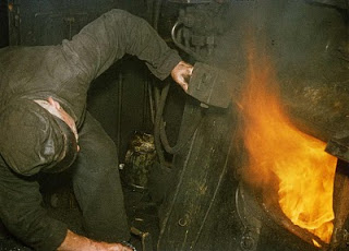
- Take a match or lighter and ignite the edge of a drowned shred at the wooden timbre. Wait a little and see the fire increasing.
- When the fire now starts to rage on the shred, you now throw this timbre with burning shred
into the pile of pallet wood under the fire arc. - Repeat the sequence 2 or 3 times but you throw the raging timbre to the right either to the left.
Now the fire is on and you need to watch the fire closely, Wood is a good fuel to fire up, but depending the state and sort of wood the fire can vanish at once then you have to start all over again.
2.04 – Proceed firing and creating pressure
Prior to the first run it is necessary to build up your pressure and fire. A good fire is one of the sources for a good production of steam.
First of all press [ N ] to increase the blower. This action increases the air flow by the develloping under pressure in the smoke box caused by the blower. The function of the blower is explained later on.
Press [ M ] to open the air damper valve/hatch under the fire grate at the ash pan.
By opening up the damper(s), the air flow then has free access through the fire grate which flows through the boiler (tubes). The damper are mounted at the rear and front side of the ash pan. Regarding the lever you will open the rear and / or frond damper when both dampers are installed.
Some engines uses a hand wheel and some uses a lever or handlebar. The hand wheel is however more precise and sophisticated in order to regulate the amount of air flow through the damper(s).
Some 3th party engines like the 4MT and 6MT Clan Class from Just Trains Expert Line uses a hand wheel to regulate the dampers. These requires special skills to drive this amazing engine properly and these skills are hardly needed at TS2015 as well. If you are not dealing carefully as it should be your engine will stuck on the run. To have the full understanding about the operations of the 4MT Standard Class and 6MT Clan Class, refer to Chapter 15 in this guide.
Now underneath the footplate there are some hatches to open up. This is not simulatied in TS2015, but in practice: you have to open up the that hatch and unscrew the nuts (if available) under the floor of the footplate just in front of the fire box. These nuts are not present on every engine. You now unlock the boiler to “move” or “slide” parralel along the frame bars of the engine. This prevent the boiler and frame bars to bend when firing up.
At both sides of the fire box a slider rail is mounted and slides over the frame bar section carrying the boiler. The boiler will expand in lenght by the increasement of the temperature. The material expand and at the end when the boiler is in hot state the boiler lenght has increased by about 3/4 inch when the engine is fired up after approx. 8 hours. When the boiler should be locked up by these nuts, the boiler and frame bars will bend.
The boiler has a fixed mounting point to the frame bar underneith the smoke box. This means that the boiler is supported at two places. Underneath the smoke box as a fixed point and at the slider bars at the side of the fire box or ash pan frame which is moveable by sliding over the frame bar, carrying the boiler.

The weight of the engine is now divided over the frame bars and wheel springs which are balanced out regulating the axle pressure.
Now the first measuremets are taken starting an engine in a warm state.
You now have to stir up the pressure and fire to get ready for the run.
Be aware if the conditions are normal, the steam engine will be under pressure after about 4 hours of firing up. The pressure is at that point not powerfull enough to drive on, but is useable to turn on the blower. This time period is based on regulair engines like a Black 5. Tender Engines needs lesser time to be pressurized.
Be shure you have open up the dampers, the blower and check the fire.
Use F4 to check the coal rate on the fire bed. If it is lesser then 75% start shoveling.
As you have done it all right the blower should be working right now.
Press [ F ] to open the fire box. (Press Shift – [ F ] to close)
Press [ R ] to increase the shovel rate. (Press Shift – [ R ] to decrease and stop)
However this is only to be done when the engine should be ready and under pressure in the shortest period of time. Though this operation to produce steam this fast, is far of the proper method to fire up the engine.
The boiler will heat up too fast and could cause servere problems later on damaging the boiler. The steal or brass will expand too fast causing tiny invisable cracks in the boiler material.
It is necessary to use the blower in order to avoid blow back, pressure drop and fire extinguishing.
Start up of a steam locomotive. Recorded in Paekakariki, New Zealand
Be shure your blower is working right now, otherwise you’ll have the risk of that blow back.
Keep the fire between 70 – 75 % !! Not exceeding 80%.
Press F4 to see the fire amount in the HUD display.
Press F5 to see the firemass in the text information left on top of your screen.
When you should exceed the amount of coal in the fire box, the chance of slack forming is increasing. At advanced engines like the Just Trains 4MT and the 6MT Class, this is simulated.
Coal slacks are unburnable contents of coal which will melt together blocking the air flow in the fire grate.

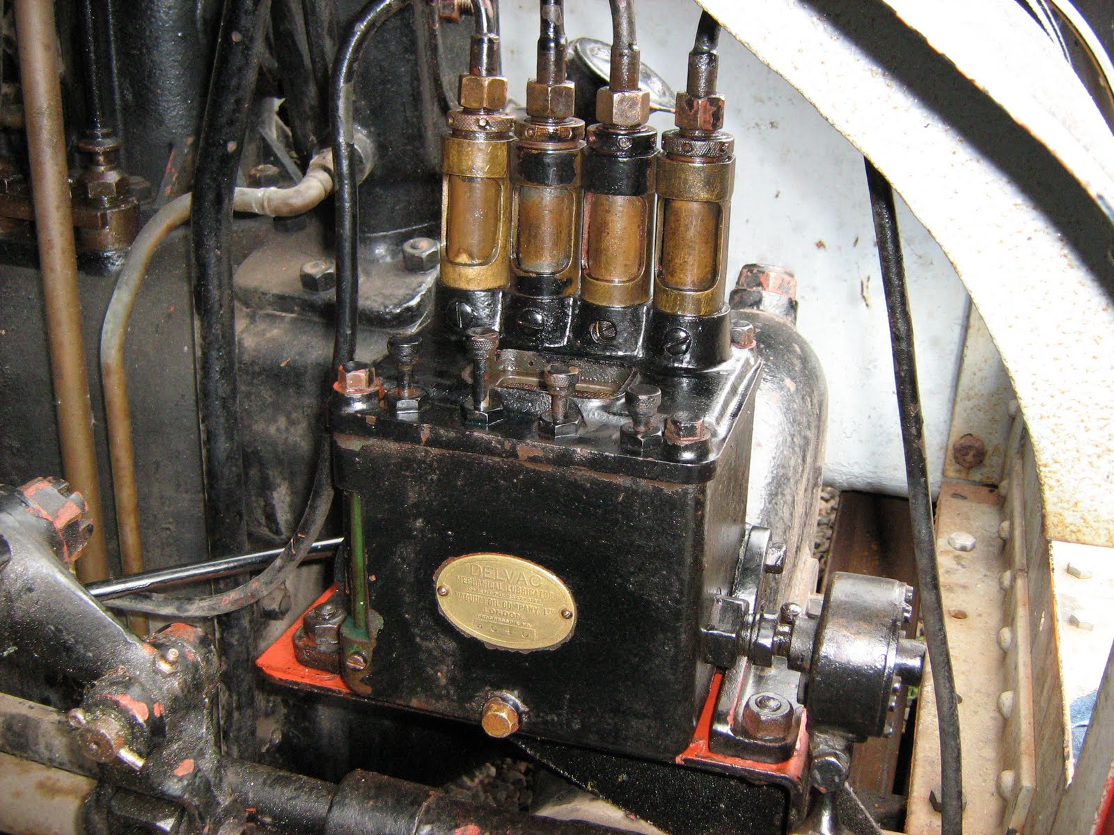
2.05 – Lubricating, an important issue
The majority of the TS2015 and 3rd party engines does not support the lubrication process.
Some 3rd party engines does have a lubrication process and within their scenario’s it is even required to use the lubricator prior to departure. The lubrication by hand, using an oil can, hand pump or grease injector for every rod, axle, bars, pins, etc, are not simulated, only the lubricator itself is operational.

Third party developer and software producer Just Trains provides the lubrication process with the Advanced 4MT and 6MT.
In order to use the lubricator make sure the engines handbrakes are set.
If you own a 4MT or 6MT from Just Trains, the lubricator is operational prior to the run when the hand brakes are set by pressing [ / ]. Then press [ Y ] for about 5 seconds.
Refer to Chapter 21 in this guide for more about the JT 4MT and 6MT Advances series.
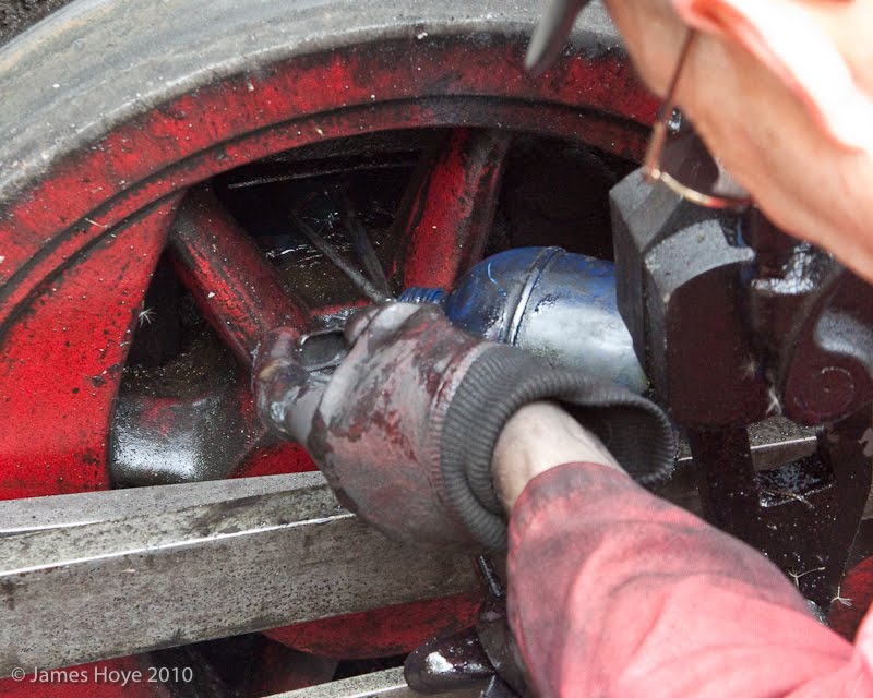
Oil is used to lubricate all motional parts at the engine. Motion is substitute to friction.
Friction causes heat and when steel becomes too hot, the steel will encounter severe damage. Axles and pistons needs to be lubricated by every time occasion. The driver checks always the temperature of the pistons, rods and bars due to frictional movements.
During the run, a rod is installed between the piston of the last axle and the lubricator. The rod operated the mechanical oil pump at every rotation of the last driving wheel. The mechanical pump then distributed the oil using a small brass pipe to the “unreachable” motional parts independently from each other.
The amount of oil for each motional part can be regulated separately depending the need and quantity of oil at every swing the rod is operating the lubricator.
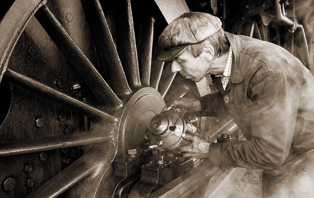
When the engine is stationary, the lubricator once and a while needs to be operated manually. Though after a period of time and prior for the next run, the lubricator spindle needs to be rotated manually as well to ensure the lube reaches of all the connecting points and surfaces of the motional parts.
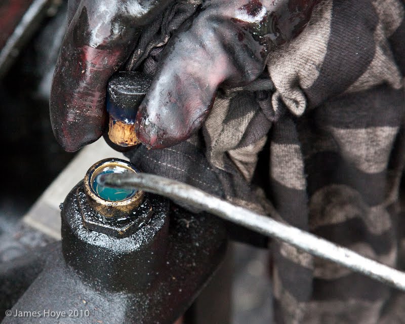
Depending the type of engine, railroad company and country you will start to lubricate when the boiler pressure starts to rise. All motional parts has to be lubricated. Once started to firing up, the oil cans needs to be filled up with the proper oil or grease. You just cannot use all sorts of mineral oil. The grease or oil must fulfil industrial lubrication requirements. Mostly this is special oil with an cohesive number.
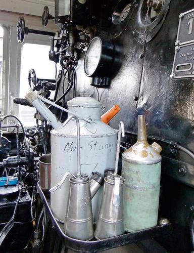
To lubricate an engine different type of oils ar used. The oil cans at German engines are assigned with colored lids for recognition.
1. Cylinder Oil (blank lid with a red A)
Oil (cohesive value: 1000) used for cylinders only, it can handle temperatures up to 400 degrees C.
2. Thick Oil (red lid)
Oil (cohesive value: 1000) used for water and air pump and can handle temperatures up to 400 degrees C.
3. Thin Oil (yellow lid)
Oil (cohesive value: 220) used at pistons, axles, rods, motional bars, levers, lubricators.
This oil is not suited for high temperatures, but can stand up to 130 degrees C.
4. Used oil.
A mixture of all oils to lubricate couplers, simple motional bars, truck pins, springs and door pins, coupler bars between tender and engine. This oil is not suited for the named equipment in the mentioned lines 1, 2 and 3 above.
5. Polishing oil.
A mixture of petrol, thin oil and think oil. This oil is slightly warm when used.
This oil is to polish the plate work of the boiler and engine. This will also preserve the plate work of the engine and prevents corroding and creates a thin layer of oil on top of the plating reflecting a half matt glossy shine effect by the sun glare or light poles.
6. Grease.
Used to lubricate buffers, coupler pins and bars, screw bars, truck studs, boiler sliders and locker nuts.
The melting of the white metal could occurred on the taps and pins connecting the pistons, rods and bars.


TS2015 simulator is quite basic, but within the range of TS2015 you can still achieve many issues concerning driving a steam engine as it should be.
2.06 – Operating the air brakes
Pressurizing the brake pipes is required to meet some important issues. After pressurisation of the pipes and reservoirs, the brakes can applied in order to release the hand brakes. Prior to that, rail shoes needs to be in place blocking one wheel of the engine. This prevents the engine (also rolling stock) to move uncontrolled, creating a run-away train.
To operate the brake pump, press [ J ] to start and run the pump or ejector.
Press [ Shift ] – [ J ] to shut down the pump or ejector. Air is filled in the air reservoir and helper reservoir.
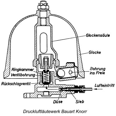
During the run, use the small ejector to keep the brake pipe pressurised. Engines equipped with a steam powered air pump runs automatically when the valve is closed. the pump remains operating because the valve does not close completely in order to keep the brake pipe pressurized.
A small bypass or small gap lets steam flow into the air pump that runs on low frequency.
This continuous operation causes the specific sound at the Knorr air pump
To fill the brake pipe quickly, use the large ejector. The large ejector does not work on all engines, but in most cases still static present. Do not forget to turn the large ejector off otherwise you will have loss of steam pressure.
When you are driving, keep up the pressure in the brake pipes by slightly open up the small ejector.
The pump feeds the main reservoir with compressed air. The main reservoir keep the compressed air to feed the brake pipes of the train, each wagon or coach does also have one main reservoir to support the brake system of the wagon or coach. Via a triple-vlave the brake reservoir, helper reservoir and brake pipes will be filled up.
The 2 steps water pump works quite the same as the water pump

The helper reservoir takes care of the direct operation of the brakes. When the air has being released out of the main brake pipe, the helper reservoir kicks in and pushes the brake shoes directly on the surface of the wheel rim. At main line engines hauling express trains, a 3-way or 4-way valve is installed on which the airflow is divided to regulate the pressure to the brake shoes to give the right amount of pressure to slow down a express train at high speed. This valve is only operated by hand and is mostly installed underneath the footplate at the driver’s side. At coaches and wagons this manual valve is also installed issuing the same function, but only for the use on the wagon or coach itself.

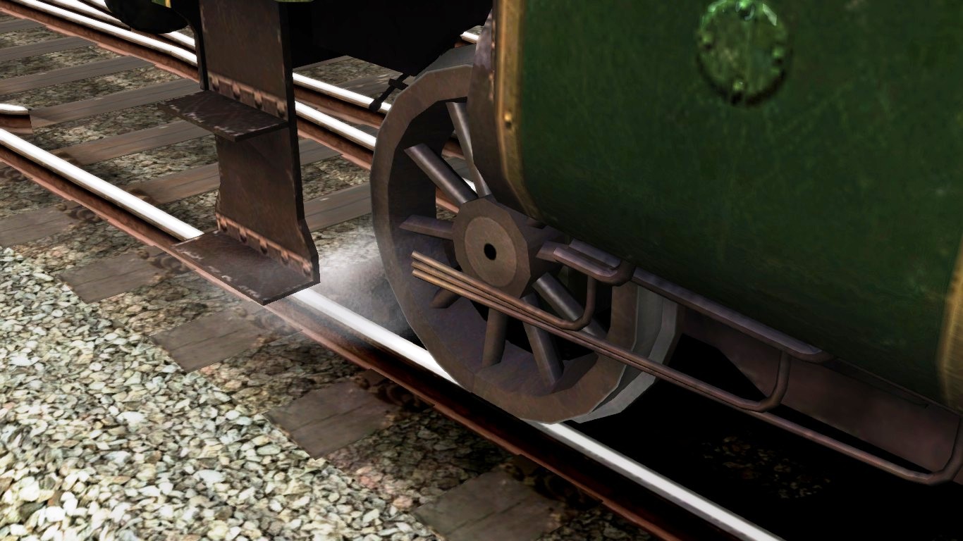
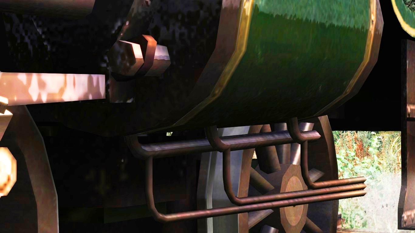
A steam engine has a divided pair of brake shoes installed to create a balance in the wheel rims of the driving wheels. The bars underneath the engine will also divide the brake power to each wheel separately, because not all axles uses the same brake force on slowing down.
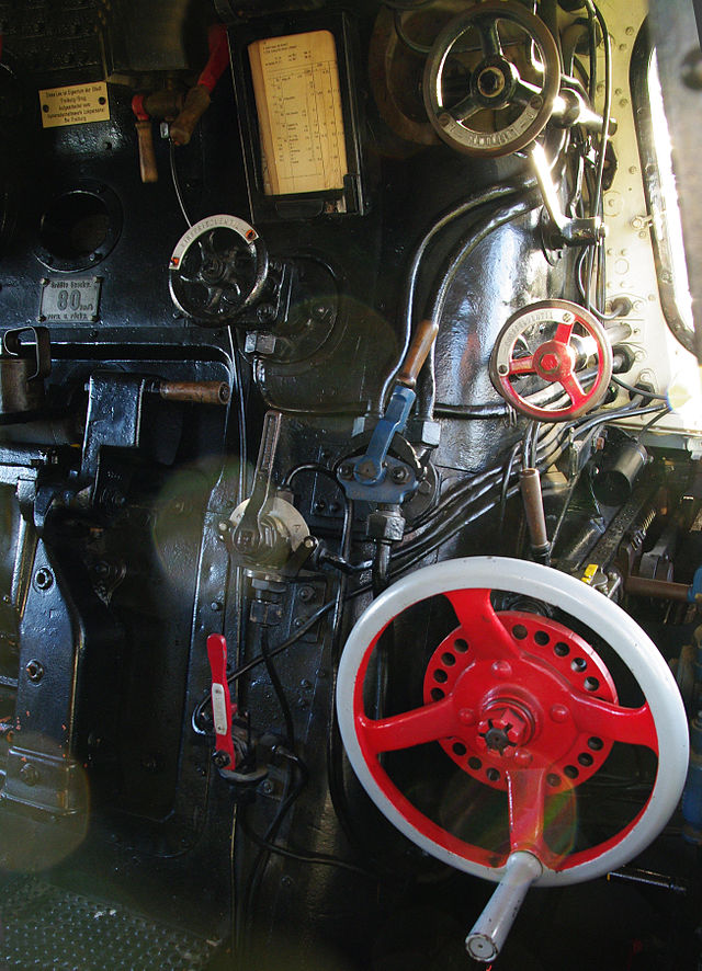
The air pump is mostly operated by an manual valve connecting to a hand wheel just above the regulator close to the front window at the drivers side.
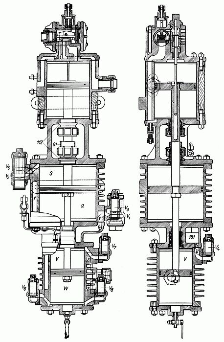
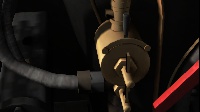
The counter-pressure brake (German: Gegendruckbremse), also named the Riggenbach counter-pressure brake after its inventor, Niklaus Riggenbach, is a dynamic railway brake on steam locomotives that brakes the locomotive using the driving cylinders. In doing so it reduces wear and tear and overheating of the driving wheel tyres and brake blocks and enables a continuously high brake force to be applied. The brake works by using the cylinders as air compressors and converting kinetic energy into heat. Steam is emitted during braking but this does not come from the boiler, it is produced by evaporation of water used to cool the cylinders.
The main part of the system is piping and regulation of atmospheric air drawn into the cylinders, into which cooling water and oil is injected. To use the cylinders as pumps necessitates complete reversal of the normal gas flow. Atmospheric air is drawn through the steam exhaust and compressed air ejected through the steam inlet. A separate chimney is provided, usually behind the main chimney, to exhaust the compressed air without increasing flow through the smoke box (which would cause increased draught of the fire).
Water injected into the incoming air evaporates during compression, carrying away much of the heat generated. Oil is also injected into the incoming air to maintain lubrication of the cylinders and contribute a minor cool down together with the mixed water. Though the use of water may not be exesive while the cylinder will encounter a drop down of the temperature. The false air will then create a draugh of false air into the cylinder and cools down severely which will result in a major cylinder block damage.
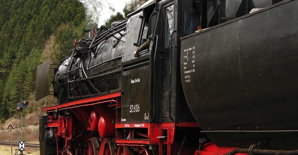
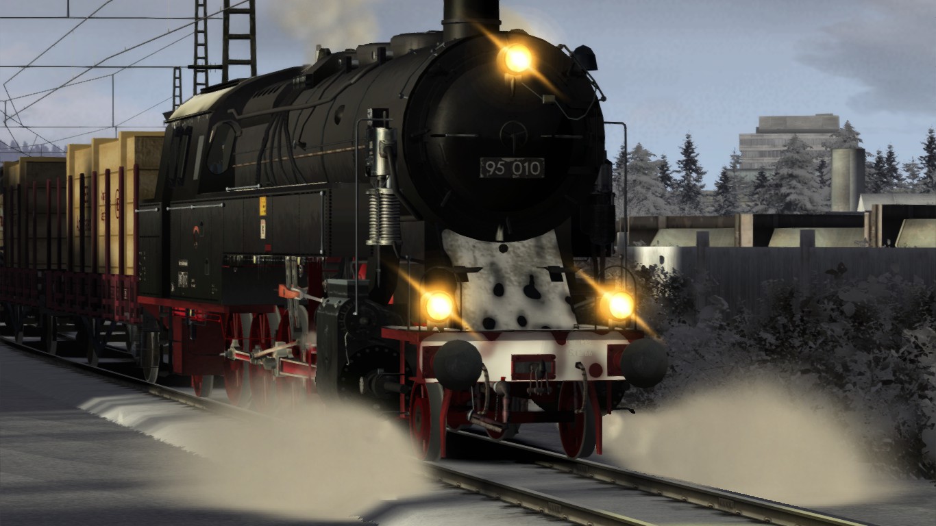
For those running the German class 95, refer to the manual provided with the German class 95 package how to use this engine and the Riggenbach brake properly. Scenarios aew included for the Seeberg Line. The Seeberg Line is available as freeware DLC in the workshop.
The German Class 95 gots a Riggenbach counter-pressure brake to slow down when the train goes down a steep slope. This Class 95 here on the Ruhr-Sieg line created by BeeKay
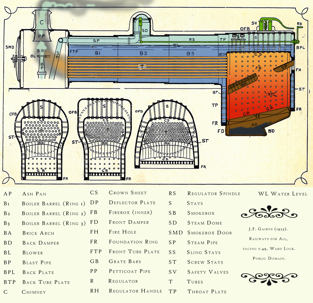
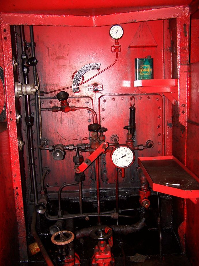
2.07 – Boiler equipment
The boiler is the power supply for the engine to get running. A boiler is a transportable power plant that delivers the energy source to the steam engine putting the train in motion.
At the boiler and around the boiler there is a lot of additional hardware, but required to get the best result of the boilers main target. “The production of steam” The inside of the boiler has been viewed already and now the external hardware is now magnified.
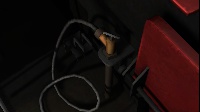
A steam driven turbo generator provides the electrical devices of electrical current. This current is needed to enlighten the cab, the head and rear lights, the AWS or other signal safety devices, the exterior light that lights the driving wheels and additional lights if necessary.
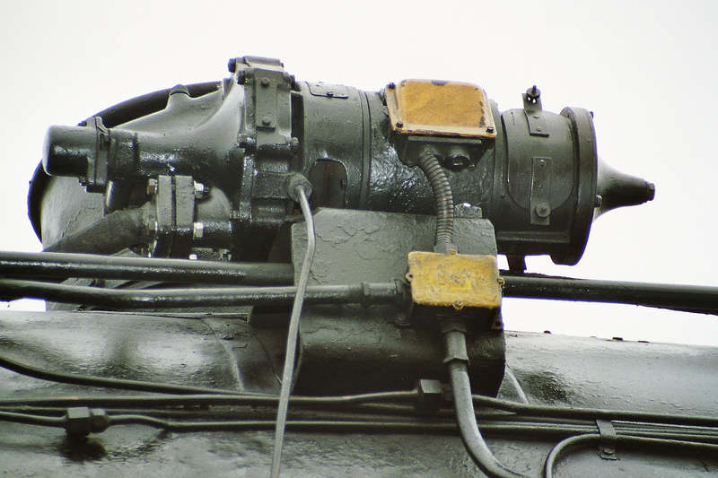
The turbo generates electrical power. The mass is directly connected with the boiler, that acts like the mass or negative pole at the engine.
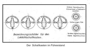
The wire is the plus (positive) pole that is fitted in a small tube that leads to the cab main switch board which is mostly mounted above the windows. The class 03 and 95 are equipped with a operational turbine driven generator and switchboard.
To operate the turbo and switch board, rotate very slowly the spindle valve clockwise that opens the steam flow to the turbo setting to rotator in motion. the rotating fan blades inside the rotator start to spin around picking up speed until about 5000 rpm producing mostly an 24V electrical current.
The switch board divides the currency to the desired devices and lights. On modern engines the electrical current is also in use for empowering the safety devices and to load battery pack in case of a malfunctioned turbo generator.
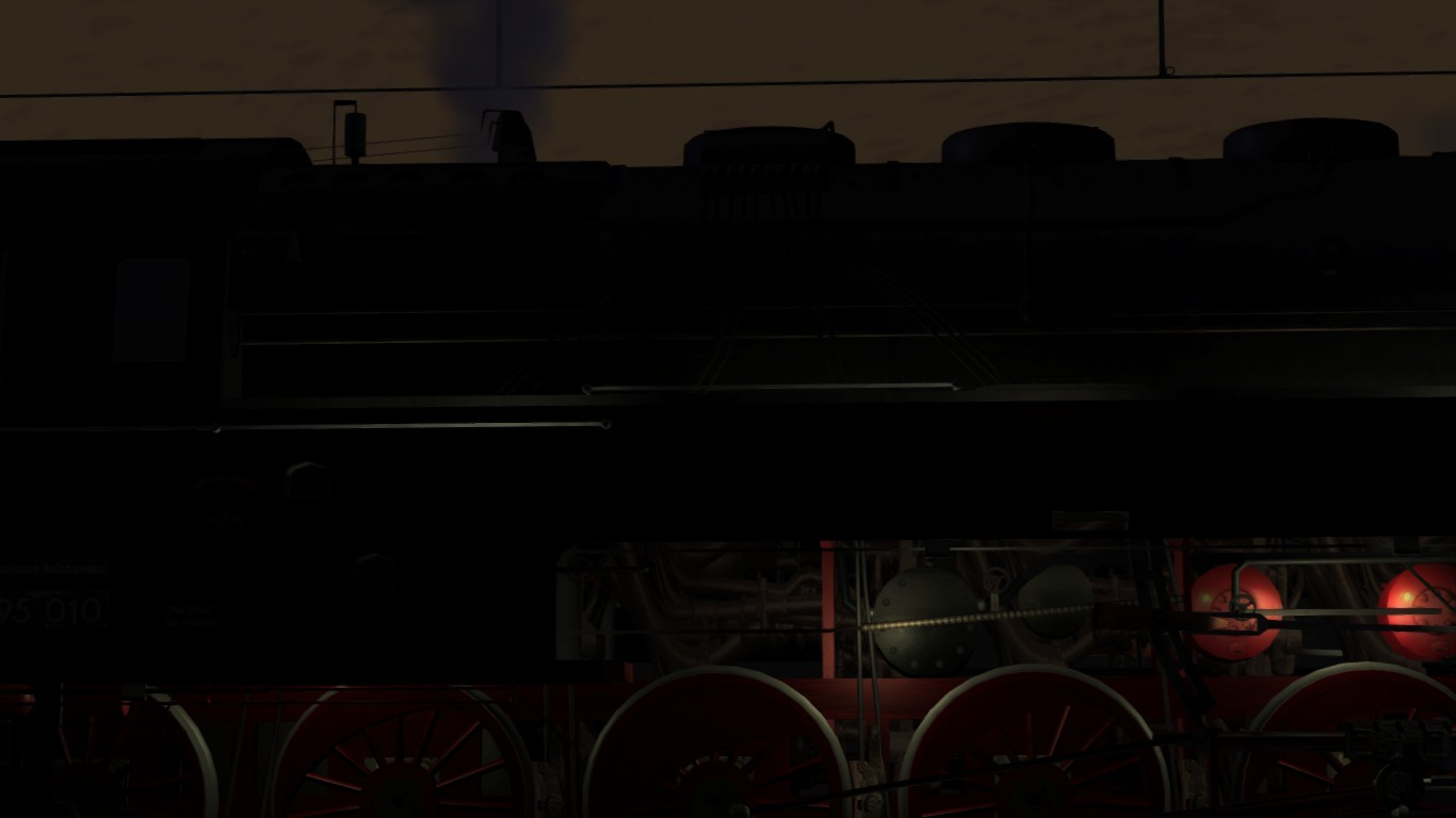
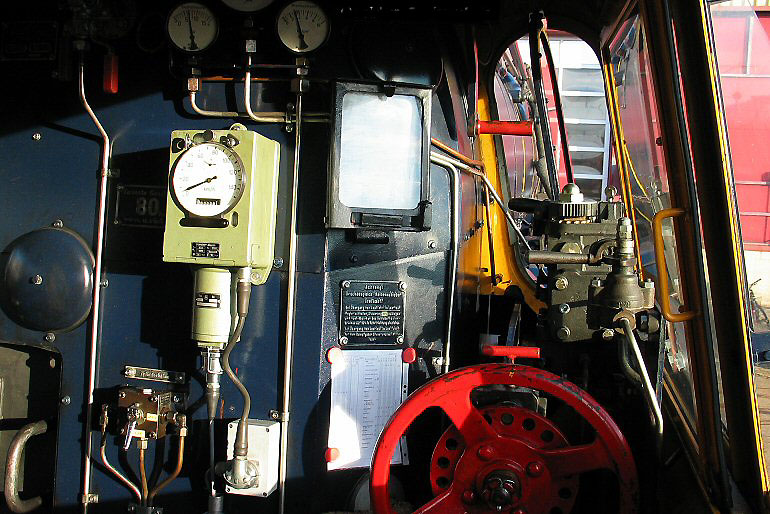
The screenshots of class 95 shows the use of the illumination of the driving wheels and the illumination of the gauges at the footplate.
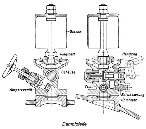
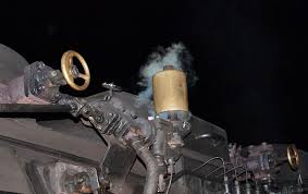
During the run the whistle is a hard and loud phonetic signal that can heard far away of.
The frequency in Hz of a whistle blow sound is widely audible and it will trigger the attention from almost everybody in the area close to the railroad. The right frequency is the source for the length in distance the sound carries away. This whistle is the common sound for approaching danger.
Secondly the whistle is to communicate between a double headed train. The first engine gives a certain whistle signal and the second engine respond to this whistle blow to confirm the signal from the first engine. Every country does have their own rules accordingly double head driving signals.
In TS2015 the [ “Spacebar” ] is in use to blow the whistle.
Some advanced engines uses the [ B ] or [ N ] for a short blow and the [ “Spacebar” ]
for a long blow.
The valve has to be open prior to the proper working of the whistle and needs to be closed when the engine is depressurized.
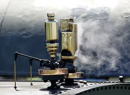
This whistle is used because of high whistle sound and often in use on local services on short distances and small engines. This type of whistle is mostly manufactured out of brass and copper. The polishing shinning effect the locomotive crew created was always known by everybody no matter which country or area the locomotive was running. The brass whistle was a famous point of recognition.
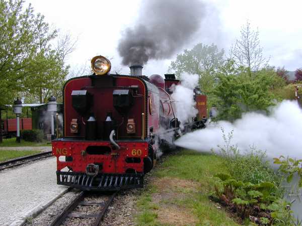
A bell gives the surrounding pedestrians a warning signal. This signal often in use on passing an unprotected level crossing which are regularly present on local lines and branch lines. All engines running on such a lines are required to have a warning bell. The driver operates the bell on approaching an unprotected level crossing.
The bell (if applicable) is in TS2015 operational by pressing the [ B ]
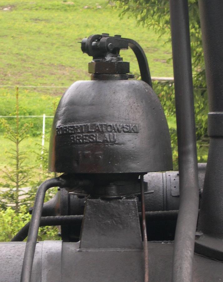
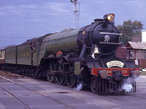
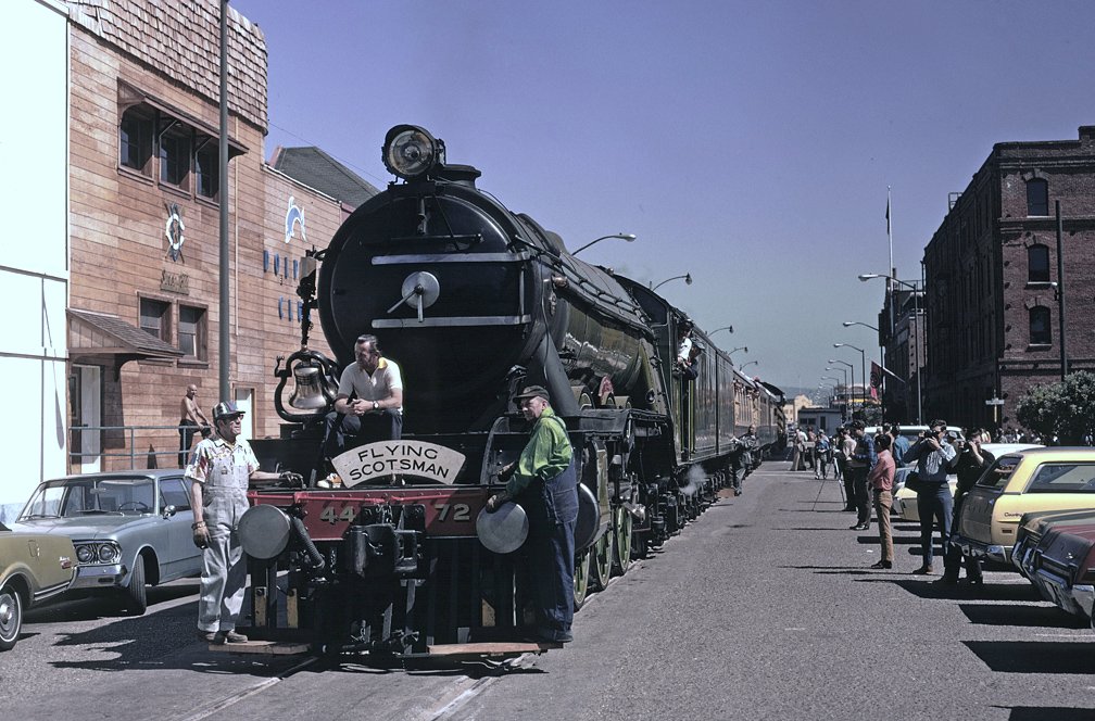
When in the 50’s the Flying Scotsman visited the USA the engine became a restricted bell and top light as well. After that visit the Flying Scotsman went back home and the bell came with the engine as a memorable gift to the BR.

Calcium sediment forms when water is boiled. After a while the calcium (limestone) will sink down to the bottom of the boiler ot on top of the crown plate. The sediment does not evaporate with the water into steam but remains behind in the boiler. During stationary periods, prior to a run or after a service when back on the shed, depot or workshop. A blow down is needed to release the sediment out of the boiler.
A special engineered valve by Ing. Gestra will release the sediment when operated.
The operation lever is installed at the footplate next to the fireman’s seat in German engines. Other engines does have other systems to release the sediment. The operational sequence.
- Inject water until 85-90% boiler content is reached.
- Unlock the lever wing screw
- Move the lever and hold for 10-30 seconds
- Set back the lever and screw the winged screw tithe to the screw holder that locks the lever.
- Inject water until the normal water level is reached.
If necessary repeat the sequence for a second time when the blow off could not be conducted in 30 minutes.
During the run use the Gestra valve about every 20-30 minutes when possible. This could be on departing the station (max. about 10 seconds), passing a bridge. in natural environment like wood areas, country sides, shunt yards when possible.

2.08 – Draining the cylinders
Steam will convert back into water when steam is cooled down. Steam on its own is invisible, but the condensation of steam is visible, This is seen and is commonly noticed as “smoke” or steam clouds. The steam particles will bound together (condensation) and becomes water again. Now Water is uncompressible and therefore dangerous in the cylinder if not drained of. The cylinder can explode when water is pressurized if not drained of.
Draining and warming the cylinders: Press [ C ] to open valve of the cylinder drain pipe.


Set the reverser at 10%. and open the regulator up to about 15%. This action drains the water out of the cylinder blocks by steam pressure and warms up the cylinder prior to your run. It is better to warm up the cylinder blocks when you are facing a non-stop long run. During the winter, at cold an rainy days, it is always required to pre-heat the cylinder blocks for about 5 minutes prior to departure, using the described method. Even more important when the temperatures sank down below zero. Always use this method to pre-heat the cylinders.
In some occasions you have to use a shred drained in oil and ignited with a match in order to de-ice the cylinder drain valves and pipes underneath the cylinder blocks.
Depending the type of loco and the scripting the creator/developer has implemented of the virtual loco have in your “shed” it will not always simulate the water draining unless the engines sets of. In reality the steam is blowing the water out of the drain pipes producing an amount of steam in front of the engine.
The water will be blown out by steam force.
Even though the cylinder blocks needs to warm up this will prevent the cylinders from malfunction. The difference in temperature inside and outside the cylinder can be that much the cylinders encounters the expanding friction of the steal which gives invisible fractures in the body of the cylinder. Even the lack of lubricating can harm the inner cylinder surface, the outcome of both issues will impact the run and cause server damage to the cylinder.
The cylinder could easily jam at once breaking the pistons off from the wheel taps.
When all the motional force is transmitted onto the piston when it comes off from the wheel tap, the weight and force of the train is released into the off coming piston. These pistons will become a fatal projectile. Striking and slicing everything that comes along the path of that piston. It easily cuts a “Peterbuild” 18-wheeler road truck in pieces.
When priming occurs. Water will get into the cylinder by steam force.
The springs however are tightly mounted and the spring are firmly pressing a valve at the small gap in the cylinder block.

This valve can stand a steam pressure easily, but will open the spring valve when water is pressing from out of the inside of the cylinder block by the tremendous water pressure and water is drained out under high pressure. When the water pressure continue to increase, the pressure will pushes on the surface of the cylinder lids, the spring holder, spring valve, the spring itself and the mechanical parts will still be ripped of by the power the water has at that moment. In the worst case the cylinder block will burst open causing a tremendous damage and could cause also a derailment during a run.
Opening the cylinder drain pipes on departure
2.09 – Topping up the supplies
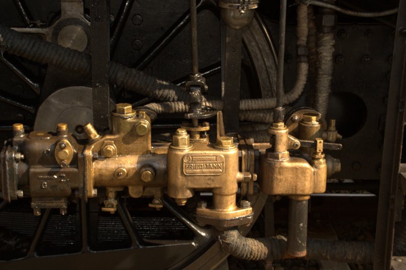
One of the basic important requirement to create steam is water, the most important substance needed at a steam engine. Now to inject water into the boiler you need to know how the injector works.
It is quite simple. Add steam to water through a narrow funnel or conic shape gap, then it expands and pushes the water with power. The gap is not bigger then a finger tip creating a tremendous force that overruns the steam pressure resulting the filling up of the water level. Based on this principle the boiler is feed by hot water.
Press [ L ] and hold to open the water flow to the Live injector until the valve is completely opened.
Press [ O ] to feed the injector with fresh steam.
Shut the injector down in opposite sequence.
Press [ O ] to close down the steam feed.
Press [ Shift ] – [ L ] and hold to close the water feed.
The exhaust injector is not working properly when the loco is not running,
because there is no exhaust steam.
To use the exhaust injector:
Press [ K ] and hold to open the water feed to the exhaust injector until the valve is completely opened.
Press [ I ] to open the exhaust steam feed.
Shut down is also in the opposite sequence:
Press [ I ] to close the exhaust steam feed.
Press Shift – [ K ] and hold to close the water feed and wait until the valve is completely closed.
Do not leave the water valves open. The water will flow through the injectors drain pipes on the track(side) and at a certain point by surprise you will encounter an empty tender while you had topped up
Always open up the water first, then steam. This prohibits the injector to get overheated.
An overheated injector will malfunction. In practice you should cool down the injector when
malfunction occurred. Take a bucket of water and throw the water over the malfunctioned injector. Do not do that too often, because a sudden cool down will crumble the injector as well.
Keep the water between 70 – 80% during a regular run.
In practice you have to be aware of the False Air flow Back which occurs when other values on the reverser remains present instead of the 30% and 70% positions. This is will cause “False Air” which will “suck” through the chimney into the cylinder and might damage the cylinders because of the sudden temperature drop.
The working of the injector is seen here in this sketch;
Steam feed (red colored) can be applied by pressing the [ O ] (Live/fresh steam)
Water feed is bleu and applicable by pressing the [ L ] (Live/fresh steam injector)
The white area is the water overflow.
Water is drained off when the balance between fresh water and fresh steam is incorrect.
When the water feed and the steam feed are in the right balance, the water will flow through the purple pipe into the boiler.
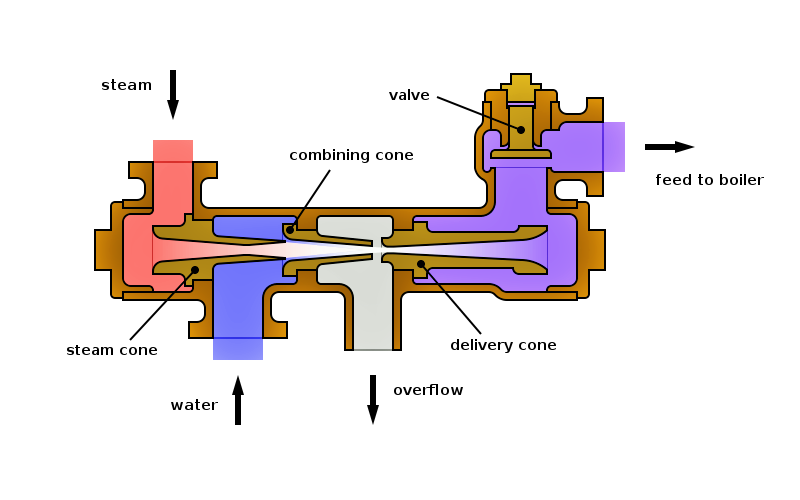
However the proper working of the injector depends on the balance between the temperature and the amount of pressure of fresh steam.
In order to get a better understanding, watch the next short educational film about the working of the injector.
During and after injection keep an eye on the water glass and if the water level does not meet the desired level. Stop injecting after 2-3 minutes to cool the injector, wait a little while and start over again injecting. if necessary use both injectors at the same time. Do not inject water for a long period of time.
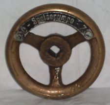
The water pump is a pump that excists out of three main parts. The steam cylinder, the water cylinder and the lubricator. The steam cylinder drives the water cylinder by fresh steam power. The water cylinder presses the water by force through the water feed pipe into the boiler. These water pumps are often in use on German engines.

Press [ T ] to fill the tender.
Press [ T ] to fill the coal in the tender.
In order to use the hose, at some engines turn on the sprinkler system of the ash pan or smoke box prior to the use of that hose, otherwise the water will not flow through the hose. This is not simulated.

The sprinkler in the smoke box is aimed to prevent the metal to get overheated en needs to be cool down to avoid damage on the bottom of the smoke box. An overheated smoke box can cause open gaps and will result in a false air inlet decreasing the low pressure as result of effecting the fire in a negative way.
The same sprinkler system is in use in the ash pan aiming the same reason as for the smoke box.
This sprinkler system is often in use on German engines, but in most cases static in TS2015.
When the water is topped up. Chemicals will be added. These chemicals will prevent foaming of water and will decrease the amount of calcium preventing the forming of lime scale which will stuck on the pipes and tubes causing a decrease of heat exchange into the water. If not treated well the pipes and tubes can be damaged and steam will have access directly into the pipes and tubes which will end up at least in an uncontrolled blow back giving the same effects as a molten led fuse. At depots and workshops the water in the water tower will already contain these chemicals.
Now in the post steam era at many museum lines and preserved working engines, this chemicals are present as powder or liquid. Mostly stores in the support coach for materials, supplies, equipment and employee facilities.
Sand
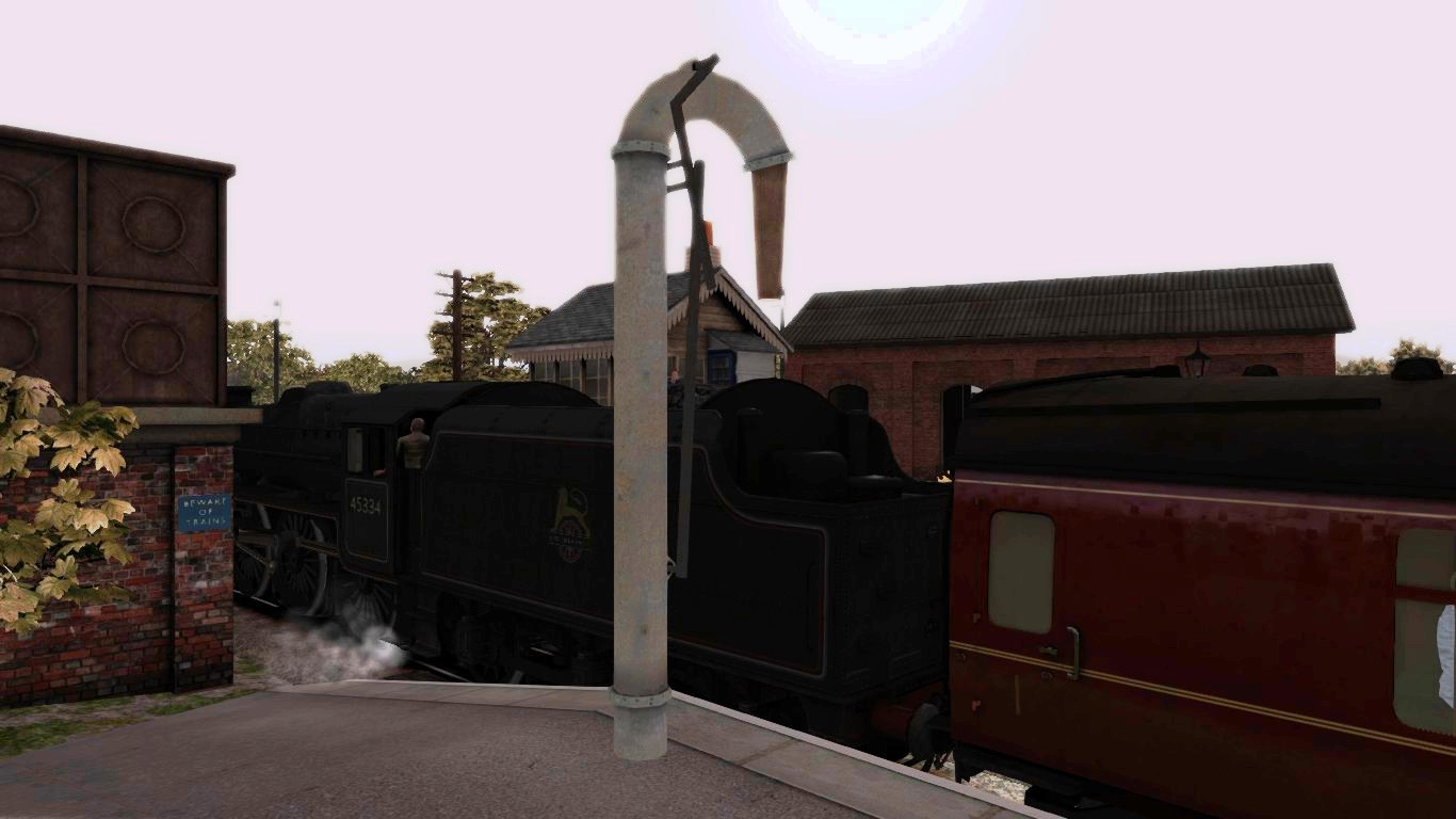
Sand is needed to increase the adhesive grip on the rail surface. The use of sand is also used to boost up the brake power in emergency cases. Sand is topped up on top of the boiler in a sand dome. The heat radiation of the boiler will dry the sand keeping out all moisture when present. Moisturized sand (mud) can block the down flow of sand through sand pipes. From the sand store, the sand is transported by air pressure through a pipe into the sand dome. To operate the sander press [ X ].
Some engines are enhanced with a sand loader system. To operate the sand loader drive the loco underneath the sand loader open the dome lid using [ Z ] and press [ T ] to load. This system is included at the Romantic Railroad Class 03 and Class 95 add-on’s from BeeKay / Just Trains.
When the sand, water and coal is topped up the engine is ready for departure. Do not forget to close the dome lid using [ Z ] when driving the class 95 or class 03.
2.11 – Departing, acceleration and stoking
211 – Departing, acceleration and stoking
On departing, open the cylinder drain pipes as mentioned in Chapter 6.
Open the regulator up to 75%.
Set the reverser at 70% according the direction you need to go and release your brakes
by pressing [ ; ]. Decrease the blower rate using [ Shift ] – [ N ]
Do not inject water on departure !
You need your steam (chest) pressure right now in order to accelerate and gain speed.
Do not forget to release the hand brake as well when applied !
Press [ / ] to release the hand brake if applied.
Decrease the reverser rate in balance of picking up speed and check you main pressure gauge.
Increase the blower.
When driving at about 10 Mph / 15 Kmh.
Close the cylinder drain pipes by pressing [ C ].
Reduce the regulator until about 60%, this is the most efficient position for a regular engine.
When running a tender engine, 30-35% will do fine.
Decrease the reverser accordingly:
Although you have to “feel” then you know when to reduce the reverser.
Check out the speedometer. When the meter stuck at a certain speed.
Reduce the reverser and the engine picks up speed again.
Here you discover the working expansion of steam in the cylinders.
Engines has a lock-up lever connected to a nudge which locks up the reverser.
Mostly press [ E ] to lock / unlock the locker if applicable and/or working.
The use of the lock prevents the pistons to “swing” on their own resetting the reverser in opposite direction. In history some major accidents has been taken place due to the lack of locking the reverser. The forces on the pistons will have “feedback” in the reverser causes the bars and the pistons of the lever to adjust the position of the reverser. In the case of the disaster the pistons has moved the reverser in opposite direction causing the engine to run backwards causing a server disaster with many casualties.
On slippery rail/track use sand by pressing [ X ] and hold the sand for a while.
When the train slips (skimming), cut off the regulator and slightly open up again until the train picks up traction. Do not use sand when passing point and slips causing the moving parts to stuck by the amount of sand.
You will need sand on climbing slopes, heavy trains avoiding slipping and loose of traction
Reduce the blower rate in balance with the use of the exhaust, regulator and reverser.
Stoke the engine during acceleration and keep the fire between 75 – 80% !
On small tank engines like the J94 of 3F keep the fire between 60 – 70 % !
Do not stoke when stationary at public stations and platforms unless it is really necessary.
You will pay the laundry for the passengers near the engine.
The tiny coal dust and particles unable to be catched by the spark arrestor will exit the chimney and settling into the water condense, the coal particles will come down with the condensed water as fine rain creating tiny black spots and dots on the clothes of the surrounded pedestrians.
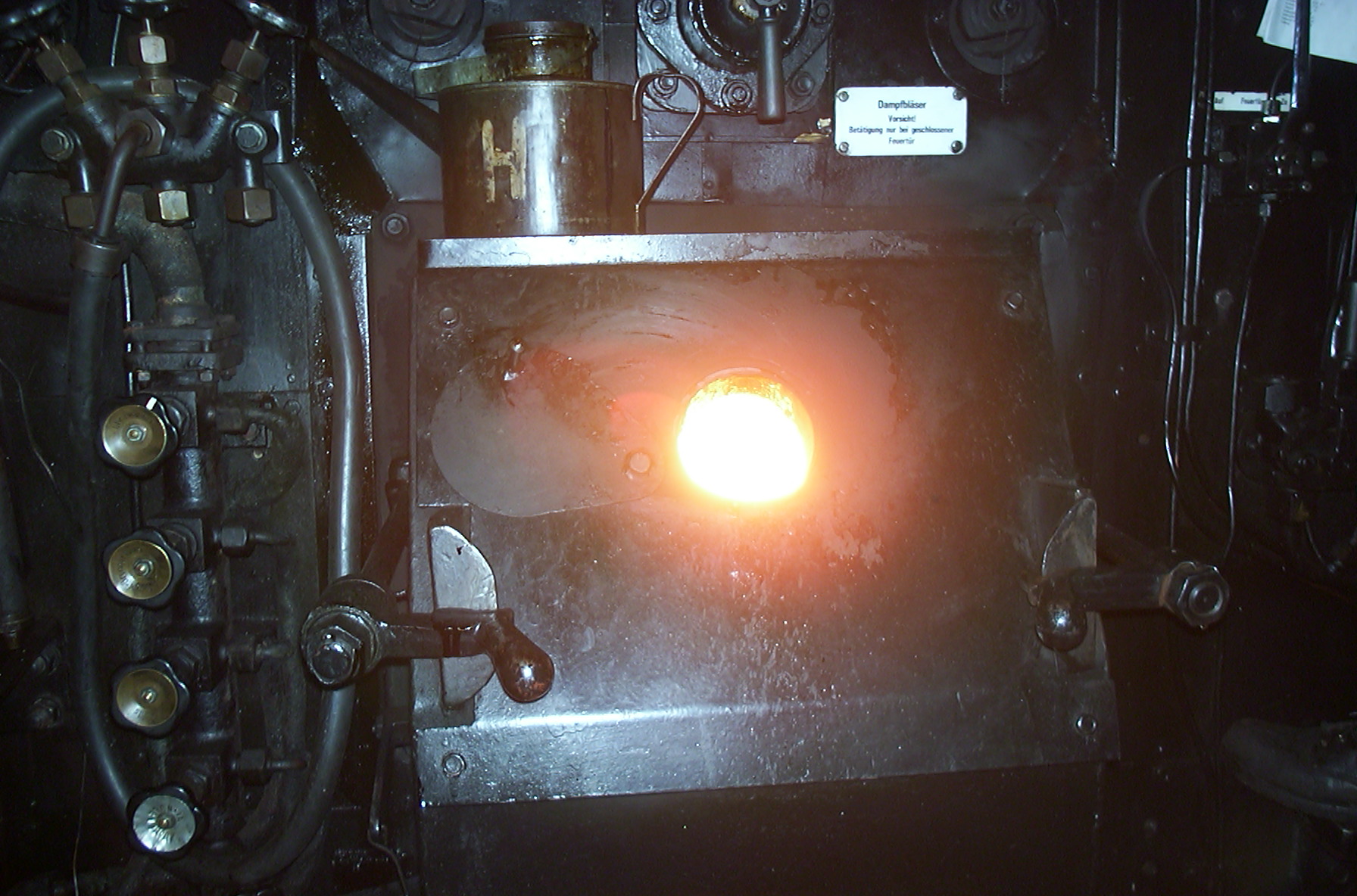
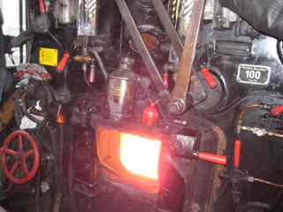
During stoking, the temperature in the centre of the fire will increase during acceleration and run, the temperature then will last up to 1500 degrees Celsius which is even hotter than lava.
The colour of the fire is then bright white and hard to look at. The arc mounted at the back of the fire box will create a “tornado” like airflow mixing up all hot gases prior to their motion through the pipes and tubes.

Watch the colour of the smoke coming out of the chimney. If the colour is light grey almost white, then start shovel. You need all your steam power to accelerate and hauling your train.
The exhaust will act like a blower as well. Now the blower will act only as an adjustable blower.
The working of the blower has been taken over by the natural exhaust of the engine.
The exhaust works when fresh steam feed is decreased. The exhaust is the expansion of the steam at the moment the reverser rate is decreased. Due to that expansion the engine get the full result from the power of steam. Though the reverser and regulator has been cut off, the engine still picks up speed. This is the final result of expansion. To keep the speed you have to decrease the reverser even more. The motional pistons now “translate” this power onto the wheels into a circular movement causing the train to drive.
Do not inject water and stoking simultaneously in order to prevent malfunctions of the injector and the possibility of a blow back.
Unless extremely nessesary, use both to top up when the water level has dropped that much facing a dry crown plate of the fire box.
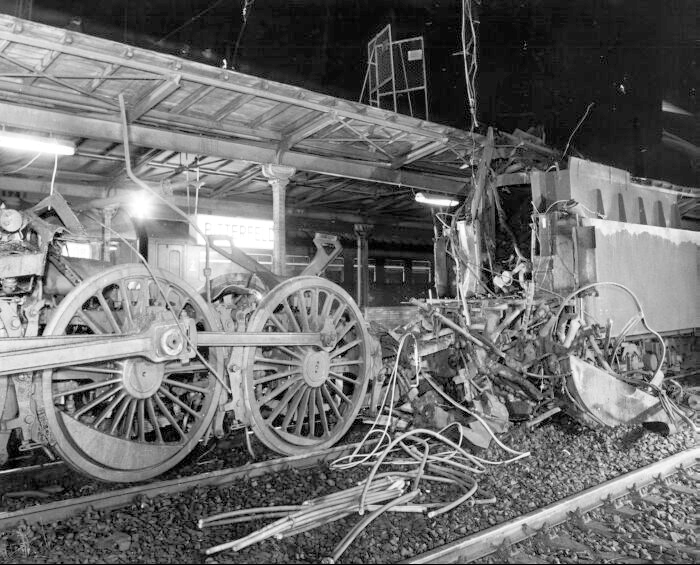
The fuse plus was covered up with calcium. The low water level was still covering the crown plate. The stopping train resulted that the water moved to the front away from the crown plate. Because the fuse plug was covered up with calcium, the fuse plug was malfunctioning.
The boiler ripped open and depressurisation causes the water to turn into steam immediately.
When the pressure is at 220 PSI / 16 Bar, the boiling point of the water is then at about 200 degrees Celsius.
Because the pressure dropped at once to normal conditions (about 20 PSI / 1 Bar) the boiling point of that water in that boiler is dropped with it to the common 100 degrees C. and turned into steam at once creating the major explosion.
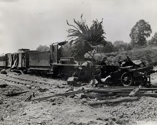
These are just some examples of boiler explosion. There has been more explosions in the past, mostly because of human failures or mechanical causes. In most cases driver and fireman lost their lives.
2.12 – Stoking using heavy oil
212 Stoking using heavy oil
Engineers were continuously seeking for method to overcome economical issues trying to find the best advantages and profitable ways to create steam effectively. Even after the war the request to get the best for the lowest price resulted in overhauling engines to re-establish the transportation and infra structures and economical contribution in the shortest period of time.
To achieve this target engineers start to reconstruct the steam boilers in high performance boilers that could last longer producing more steam on an average steam locomotive. Coal became ineffective and was expensive. The solution was to install special burners into the firebox to burn heavy oil. Heavy oil was cheaper than coal.
The profit rate of heavy oil was even higher than the profit rate of coal. Firing the engine became much easier and the use of heavy oil made it possible to switch off the fire when the engine is stationary. New steal boilers were welded instead of riveting and lesser steam domes were present. The fireman has less work to do and the physical stress due to the duration of shovelling was eliminated.
Engines that remains on coal firing were scrapped 5 to 6 years earlier prior to the scrapping of oil fired engines.
The oil firing in TS2015 works the same as coal firing. Actually the meaning is different
- Open the oil valve press [ F ]
- Closing th oil valve press [ Shift ] – [ F ]
- Increase oil amount press [ R ]
- Decrease oil amount press [ Shift] – [ R ]
To fire up a oil fired steam locomotive you need to have pre heated oil the viscosity of heavy oil is like thick syrup and needs to be warmed up to get the oil liquid to flow. Now when a pre heat system is not present the oil needs to warm up by an extended heat source. This is usually a coal fired engine. The steam produced by the coal fired engines will heat up the oil in the tender up to a 110 degrees C.
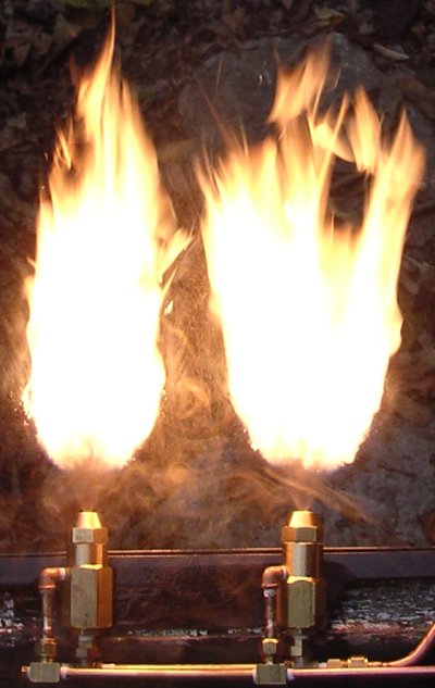
The oil now can be pumped with the use of the external steam source through the atomizers that are installed just above the fire grate. This fire grate does not have the coal grates but does have a few bars between left and right to let the air through.
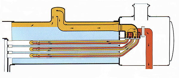
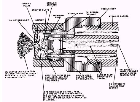
An atomizer sprays the oil into the fire box using two nozzles. The nozzles are mentioned in the diagram and shows the working of the oil atomizer.
The firedoors does have a small gap for two reasons.
1 – To check the fire.
2 – To insert sand.
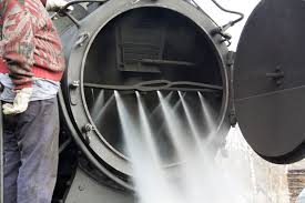
Sand is used to insert into the fire box to clean out the tubes and pipes. The sand acts like a grinder that “grinds” tubes and pipes surfaces from adhering oil and/or tar. The sand forms small chunks of tar that is blowing out through the chimney or falling down in the smoke box. These oil components are non-combustible and if not cleaned these oil/tar will result in the same effect as lime scale in the boiler itself.
The two nozzles / atomizers are separately adjustable. Every nozzle works fine when the oil pressure is balanced at about 2 Atm. per nozzle. The high temperature ignites the oil directly creating the super hot gasses that is lead into the tubes and pipes generating steam. The pressure that the nozzles contains are separately readable by gauges that are installed in front of the fireman.
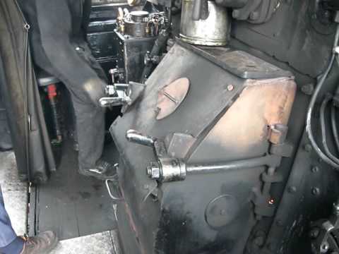
Close to the fireman a bucked of sand with a small shovel that is used for insert sand through the gap in the fire box door. The fire box door is only opened for maintenance and is locked up with the lockers that are present at the side of the fire door.
When heavy oil is pushed through the nozzles in the fire box a second nozzle blows steam under high pressure against the oil stream from underneath that atomize the oil which ignites immediately. the steam injection and the oil flow can be operated separately and can be fine tuned due to a series of valves which is installed left from the fire door.
It was even possible to top up the oil supply directly from the wagon itself if a bunker storage was not present.

The 52 8055 is recreated by the Swiss compagny DLM at Winterthur. The engine is fired by
light oil and one-man-operational. The sliders at the crosshead contains roller bearers and approved for 62 Mph / 100 km/h.

2.13 – During the run
Now you are running on the track, you now have to deal with a lot of situations.

Keep also monitoring the water level regularly.
Do not inject water until the run becomes stable.
This is also the reason to top the water up when the boiler is in state of “rest”.
Press [ K ] to open the water feed of the exhaust injector. (Press Shift – [ K ] to close)
Press [ I ] to open the exhaust steam feed.
Press [ I ] once again to close the steam feed when ready
Do not use two injectors at the same time as mentioned before. This will cause a steam pressure drop unless it is necessary due to some tremendous drop of water level in the boiler.
During the run, use the Exhaust injector. When stopped, use the live injector.
Prevent the drop of water level less than 70%.
Less water will result in unnecessary usage of steam.
The evaporation surface will increase on the decreasing of the water level which causes more stoking in order to keep up the water level.
You need to inject more causing steam usage which is resulting in a increasing rate of coal consuming. You then need more coal to keep up the pressure.
This is why you have to keep up your fire and water level
Easy to remeber: Keep it up above 70%
An exception is the Challenger and Big Boy. Keep the water level above 96%. The amount of water use is tremendous. To keep the water evaporation surface as small as possible, it is necessary to keep the water level as high as possible.

- Stoke 8-10 shovels at about 10 kg of coal per shovel you throw.
- Check pressure
- Inject water (Exhaust steam)
- additional Inject water (Live steam) only at low water level.
- Check steam chest pressure when driving.
- Check brake pressures.
- Adjust the use of the small ejector
- Check water level
Before you set off. Test the injector use by using the HUD display. After checking and taking notice the motion and position of the valves, you now can rely on the manual use or by mouse. Check the water valves if they are closed well after closing the steam valves of the injectors. Pressing F5 after closing the steam valve shows the tender water level slowly decreasing. This means a valve is still open when the injectors are not running.
Another way of checking the water overflow is by hanging out the window and look down. Here you better go outside next the cabin using camview by pressing [ 2 ] and aim the view on the injectors. when water comes out, the water valve is open.
Make adjustments to the blower rate if necessary in addition of the exhaust.
Increase the blower rate in balance of the decrease rate of the regulator and/or reverser.
Check the colour of the smoke, when the smoke is light grey, it is time to shovel again. Stoke about 10 shovels at a time until the smoke is dark grey.
The use of steam and water depends on the use of additional equipment resulting in about 4 – 5 cubic meter of water extra over a distance of 125 miles / 200 km. In the winter even more because of the steam heating when you haul a passenger train. Then you can last up to 125 miles / 200 km.
You shovel about 1000 kg of coal at a distance of 35 miles / 50 km. Every 2 – 3 minutes depending the weight of the train, the type of landscape, the weather conditions and the state of the engine could also results to shovel every 1 – 2 minutes shovelling the coal on the fire grate.
With a rate of 10 shovels in the frequency of 1 – 2 minutes, every shovel contains up to 15 kg. of coal depending the size of the shovel. After 125 miles / 200 km. 4 tons of coal are consumed by the engine in normal conditions. Also in the winter the amount of coal consuming increases and is in balance with the use of water. Depending your stoking experience you are able to stoke and safe coal consuming.
The best way to stoke is to maintain the Horse Shoe fire. Less amount coal in the front and middle of the fire grate and a high amount of coal at the left and right side of the fire box and grate and high amount of coal just underneath the fire door opening.
The coal will scatter down to the front by the humping and bumping motions of the engine.
Now the fireman have to stoke at the front edges of the fire box, but still covering the fire grate to prevent a cold air flow in the fire. Looking top down on the fire grate will recover a “Horse Shoe” shape at the coal bed.
When approaching a tunnel, be sure your blower is on and the fire door closed. Open the fire door will result in a blow back. During a passing through a tunnel, your fire should be in an state of “Rest” with no fresh coal on the fire bed. Keep the blower running during the tunnel passing. Use if necessary the live injector to feed the boiler. Also to prevent the waste of pressure when present in the boiler When exiting the tunnel start to stoke immediately.

This shows the direct need of cylinder drain pipes in case of doubt, just open the water drain to drain off the water.
Better you lose pressure instead of loosing water.
Loosing water will cause a boiler explosion causing casualties an injuries.
If you are doubting. Stop that train! no matter what!
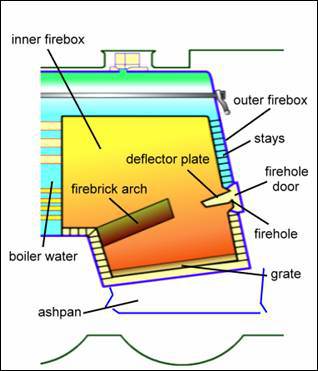
Then: In practice. Open the ash pan and rock the fire away from the grate. Safety first at all times. On top of the fire box there is a safety plug of lead. When the water level drops below the top surface of the fire box the plug will melt and steam fills the firebox with high pressure. Causing the fire to extinguish. When this safety plug should not work a boiler explosion will occur.
2.14 – Stopping a train, a skilled performance
“It is not how to drive a train, but how to stop a train.”
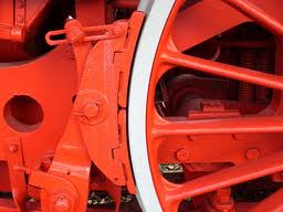
Before you start ot slow down your train, you have to be aware about the working of the brake system.
The brake system at steam locomotives contains a several major issues;
– Air pump / ejector
– Main reservoir
– Helper reservoir
– Main brake pipe
– Mechanical brake system
– Brake shoes
– Hand brake
– Locomotive brake with the additional reservoir and pipes.
– Main control equipment
– Emergency brake system
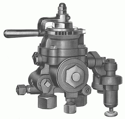
Additional;
– Vacuum brake
– Steam brake
Non steam brake system (electric and diesel only):
– Dynamic brake
– Electrical brake
– Regeneration brakes
– Magnetic brake
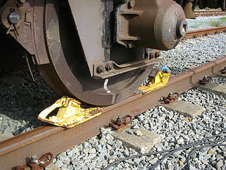
These are used to block a wheel directly, mostly used when shunting.
and trains with no brakes.
Check out the ejector. The brake pressure in the brake pipes should be at 21 PSI or 6 ATM.
Press [ J ] when the ejector does not work. You will recognize this on braking because the brake does not release and the pressure remains equal or drops further.
Decrease the regulator until about 15-20% and reduce the reverser completely to 0% open the cylinder drain pipes so water can be drained off. Your regulator is open causing steam to appear at of the cylinder drain pipes blowing out water condensation.
Open up the injector and feed the boiler with water because steam pressure should be rising now, make adjustments to the blower and check out the air damper.
Brake positions : (See sketches)
Press F4 for HUD to show the brake pressure.
Just above the pressure gauge you read out the present value of the active braking;
Working:
Releases the pressure out of the brake pipes accordingly the shown amount in % (Broken Yellow)
The helper reservoir activate the brakes (red)
Self lapped:
Brake pipes does not fill, helper reservoir does not fill. brake amount does not change
Running:
Brake pipe does not fill up. Helper reservoir is filling (light bleu)
Release:
Brakes are released. Brake pipe is filled up at 21 PSI / 6 ATM (Yellow)
from the main reservoir
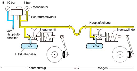

Read your brake gauge, when the needle is at 0 (Zero) then turn on the ejector.
If done the brake gauge will increase until 21 PSI (6 ATM)
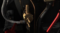

Continue to reduce the pressure and at the start of a platform you should have reached a max. speed of 20 Mph / 35 Kmh.
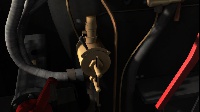
apply the brakes on the train.
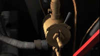

At German engines, you have the brake controls at the right side of the cab and are mostly equal to the Knorr controls.
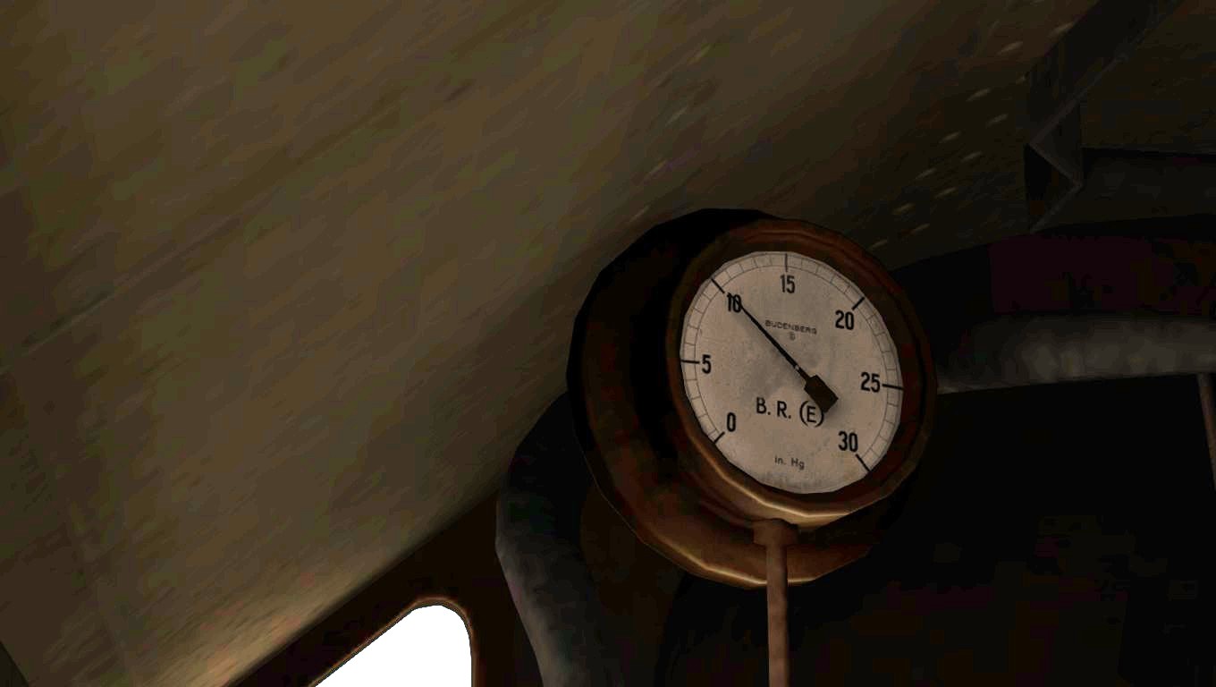
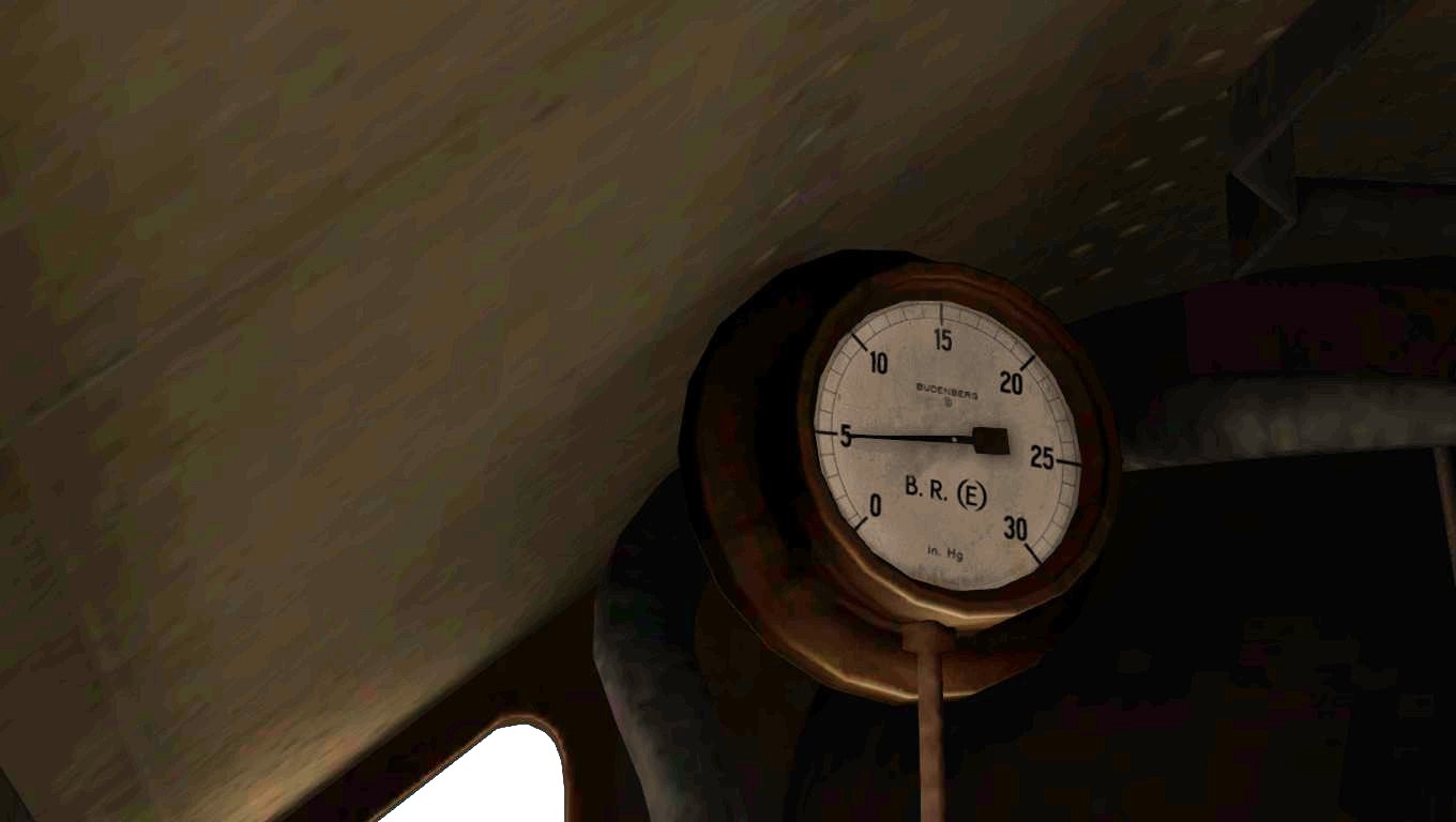
Avoid emergency brake. An emergency brake occures on:
– a passenger has pulled the emergency brake due to some major occasion.
– AWS kicks in.
– Air depressurisation due to a leakage. mostly in the coupled hoses between the brake pipes.
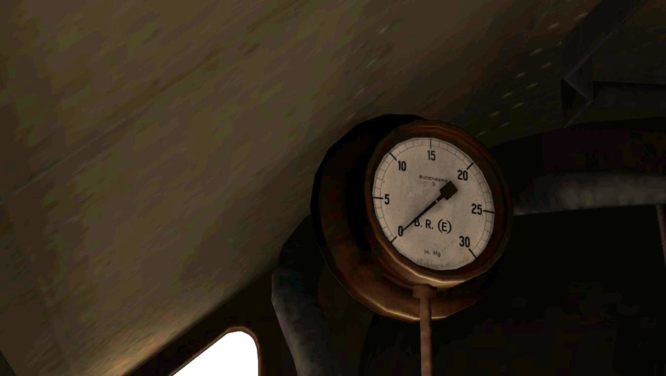
When the flat spot is too much flattened out, the wagon or locomotive needs to go the to workshop and needs to be restored or replaced. A flat spot on the wheel surface will also demolish the rail surface of the track when the wagon or engine is continuing running.
Every loop-around of that wheel will slam the surface of the rail causing tiny cracks and finally will end in a broken rail.
Cracks in the wheel will also appear in a broken wheel rim that is able comes of the wheel.
One of the major accidents that has occurred due to a broken wheel rim was the ICE accident near Eschede (Germany) where ICE type 1 at full speed (125 Mph / 200 km/h) derailed and smashed into a bridge pillar. The bridge did collapse and the most of the train crashes causing many casualties.
This small documentary shows you the cause of this major accident in 1998

In this case you have “failed” the brake sequence as it should be. This requires all your skills.
Now when you are overrun a platform that occurred due to some or a follow up from many issues. make contact with CTC and report the overrun. Inform the train chief. He will notify the passengers.
When you are driving a EMU or DMU or in ,most cases an electric or diesel locomotive mostly have a communication system to inform the passengers about the ongoing things.
Another issue is slippery rail surface. Slippery rail is often cause by oil and grease or by weather conditions. After a dry period a sudden rain fall can cause the dried oil on the rail surface to come loose and causing slipping and spinning that can avoid the whole train to stop at a platform and can even be the cause of overrunning signal at danger.
The use of sand on these type of conditions will not always pay the desired effects. When the weather conditions are changing slow down by just cutting off and brake down slowly much earlier as usual in normal conditions.
In the autumn, falling leaves will even result on slippery rail surface. Special when you are passing areas with forest and fields, expect slippery rail surface due to fallen leaves. Act on this spots like above. Using sand in addition.
Braking needs the most attention of stopping a train properly. Dealing with the issue in order to prohibit any failure will result in some negative results. The use of the brake is therefore magnificent important.
It is not because you are now running a simulation or driving a vehicle, but regardless the vehicle you drive on, the brake system of your vehicle needs to be in proper condition. It is because of your own safety and others.
2.15 – Stopping at a station, short platforms.
At the most platforms at stations it is always required in TS2015 to stop at the end of a platform.
This is usually the most common place to stop a train. In practice a passenger trains always stops as close as possible to the main exit / main entrance for passengers have rapid access to the train and exits of the station. Passengers will always hold up close to the exits, stairways and elevators.
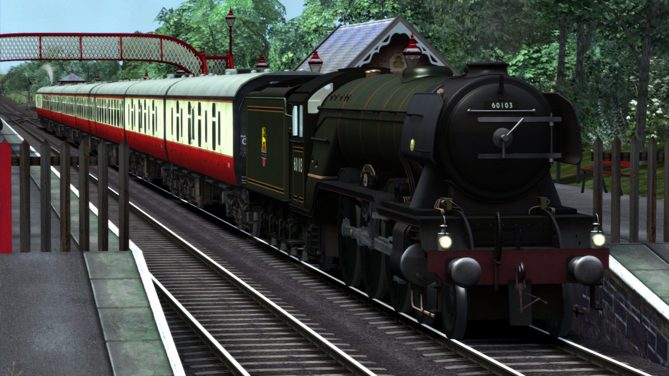
You have to be aware of the wishes of the passengers. Most passengers does not walk too far from the main exit and they always try to poses a chair close to the door, facing the driving direction and depending the left or right hand traffic either on the left or right side of the train and mostly direct behind the driver. If the coach has compartments. the passenger always find an empty compartment. close the door behind it and hopes no one will enter to gain silence and rest. The passenger experiences this spot as the most comfortable in the whole train.
Every Railroad company does have their own regulations for a specific train to stop at a determined position along the platform. This is usually a sign post wtih a number shown.
The number is equal to the amount of coaches the train consists. The engine or first EMU or DMU has to stop at about 1 yard for that stopping sign accordingly the correct train length or amount of coaches. The position of the doors now is the most economical position for train and passengers to embark / disembark.
There are occasions a train is too large for a certain platform to stop at. When a train is too large then you have to act as follow;
- Pass slowly the platform with your engine completely until the first door of the coach stops just at the edge of the platform head.
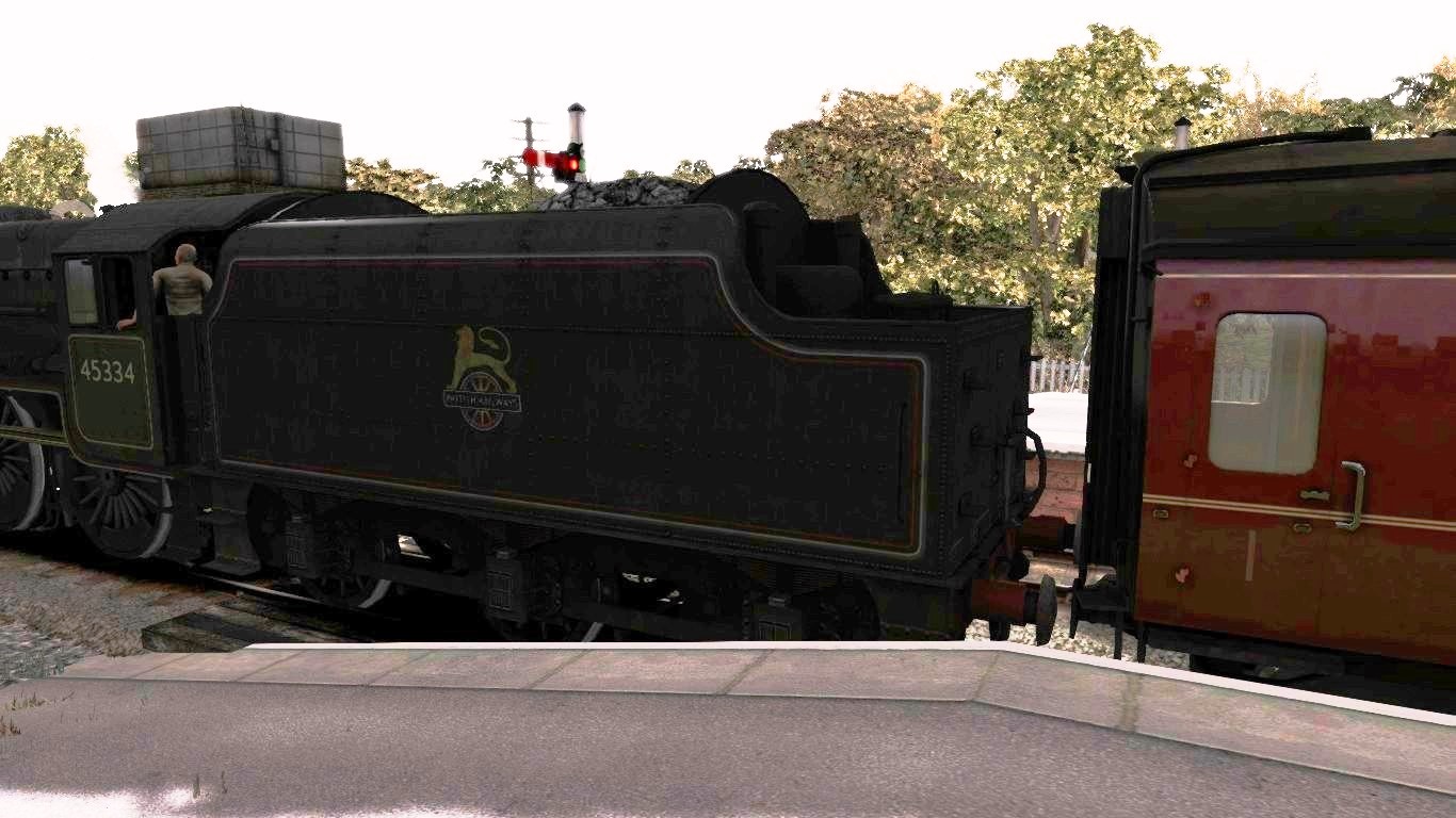
When a signal prohibit to stop the train at the proper place then the signal may not be passed.
This can be overruled when the signal man gives a SPAD order. However the last coaches are still from the platform. In some occasions the chief of the trains directs the passengers to move on to the first coach on their move which came to a stop at the platform.
In some occasions the coach could be too far from the platform. In this case the chief of the train provides the passenger a collapsible stair to position in the track ballast. Now the passengers can (dis)embark more easily instead of “jumping” on the stair or ground. This situation however is quite rare, though this (dis)embarking method is often use at tracks with a passenger train once a week in the far outer backs of countries with low population and small communities.
An example is the method used by the Alaska Railroad.
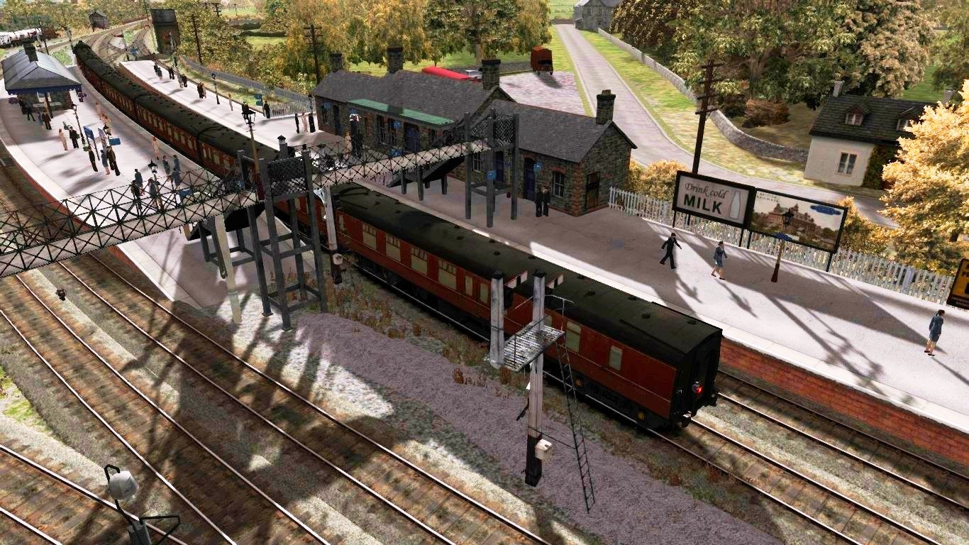
It is important to mention the things that are going around at stations and platforms. People are moving around when arriving at the station almost touching the arriving or departing train. Children running around unaware of the danger a moving trains contains. A passenger busy with other issue will miss the doorstep once and a while. In the worst cases they fall in between the platform edge and the train.
As driver and fireman you need to hang out the window when arriving at the platform, to monitor the situation. If necessary blow the whistle to avoid an accident. Do not stoke at station and try to keep up the pressure and maintain a “rest” fire. The water pumps should not be used only if necessary.
Press [ T ] To (un)load the passengers. On departure hang out the window at the platform side. Not only to watch the station / platform supervisor or, but especialy to monitor the situation. Depart with ease and softly not exceeding 25 mph (40 km/h).
When the last coach has left the platform, gain speed as usual, acting as notified in Chapter 10
2.21 – After the run
2.21 – After the run
Every shift starts and ends and it is not only driving the steam train, but nmaintaining the steam locomotive is a major task for both driver and fireman. Even in TS2015 the shut down is issues.
At the end of your shift (scenario) there are different ways to finish your shift.
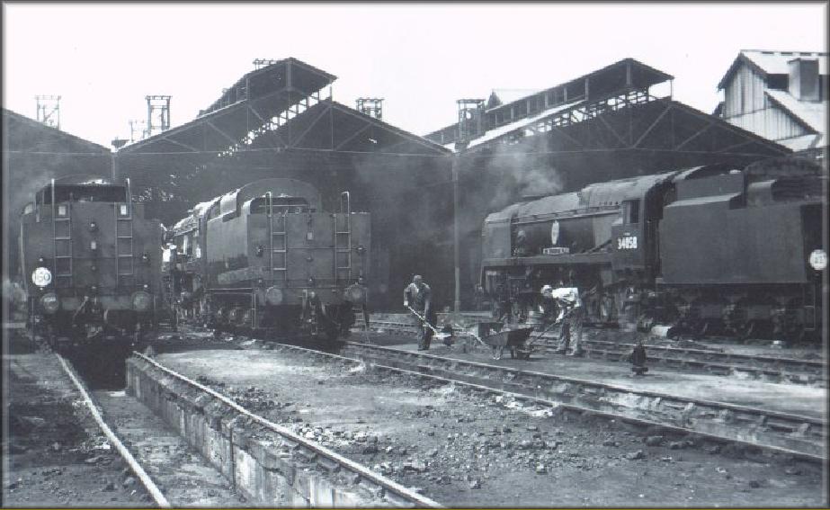
- Your shift will be taken over by the next crew.
- You shift ends at the depot or yard.
- Your shift ends at the workshop
There are many issues you have tyo deal before the fresh crew will continue the run or shift.
Before you enter the station in the last 5 – 10 miles create a resting fire, but be sure you do not gain pressure unless desired. Drive smoothly by expansion this means to cut of the reverser, cut off the blower and dampers to prevent the increase of pressure and shovel with tiny amounts of coal to prevent pressure drop and to prevent the grate to get visable. Try to keep the pressure at a constant level.

When arriving at the station and your run and shift will end prepare the engine for the fresh crew to take over.
If the locomotive is coupled and moved away to the depot you have to do some cleaning as well.
Mention the water level, if necessary inject the water until 2/3-3/4 of the water level.
Prepare the fire for a direct take over by creating a ring fire.
Prepare the fire if taken over by the fresh crew later on by creating a rest fire.
Creating a ring fire with coal
Clean the fire in the middle of the grate and move all coal towards all sides and create a gap in the middle of the fire. This is called a ring fire. Shovel some coal just under the door and keep the sides filled with a small amount of coal.
Check your water level is necessary inject water until the water scope shows 2/3 – 3/4 of the water is visable and make adjustments to the blower. the blower now may not blow too hard but just slightly.
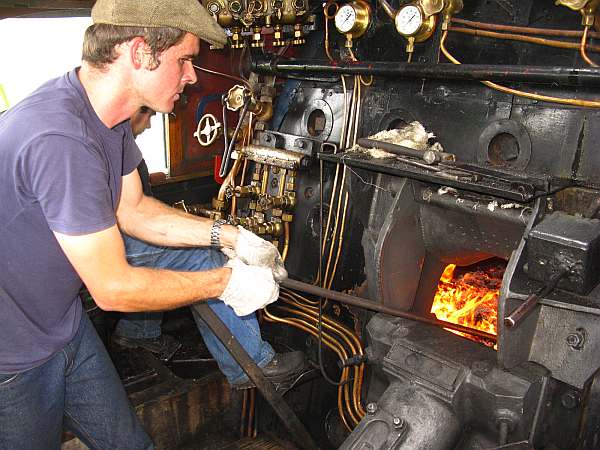
When now the fresh crew comes aboard the engine, the engine is now ready to take over by that fresh crew. All you do is handing over the key and the log book talking the issues that are going on at the moment. Then take your stuff with your companion and you report to the dispatcher and you have you time all for yourselves.

When the engine is needed at the depot you do almost the same as above,
but first you uncouple the engine
- Shunt into the yard.
- Rock the fire.
- Dump the ash in the ash pit.
- Create a ring fire and then a rest fire, or remove the fire through the fire grate hatch.
- depending the engine to get shut down completely due to maintenance works.
- Perform a blow down.
- Top up the water level.
- Clean the ash pan.
- Clean the pipes and tubes by an air lance.
- Clean the smoke box.
- Clean the footplate
- Close all valves and lids
- Move into the shed
- Cover up the chimney with a chimney lid.
- Fixate the engine by setting rail shoes blocking the wheels to roll.
- Release all brake pressure in the brake pipes and vessels.
- Cover the chimney to keep the smoke box dry from the weather conditions.
When the engine becomes unpressurized, drain the water off the boiler.

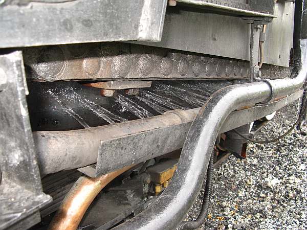

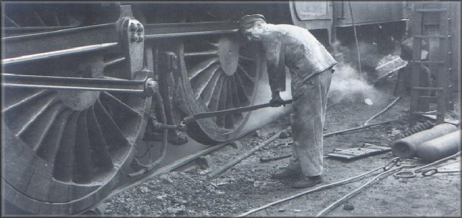
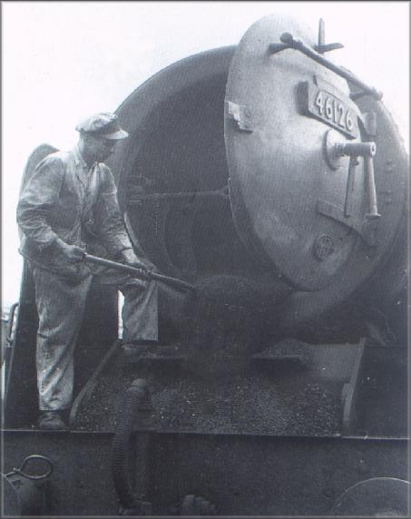
Indeed it is hard work and labouring to achieve the expected targets during your shift, but it is all part of your job.
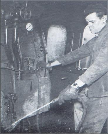
During the shutting down procedure all mechanical parts needs inspection as well especially when something has occurred the next crew needs to know about it.
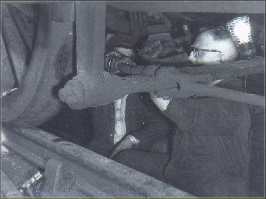
After the fire went down the pressure has dropped. the engine will now be in a state of rest.
It is better to keep the engine pressurized. This will expand the boilers life time.
After the run still check the brake shoes and other mechanical parts in order to detect any damage. Spraying the frame and mechanical parts is highly necessary to undo all parts from ashes. However water is not a good issue to use due to corrosion and rust. make sure all the parts are lubricated. The lubrication of non motional parts will have the advantage that all steal, iron and other materials painted or not, is kept free from rust and corrosion. Oil will reject water naturally and is therefore perfectly suited to preserve all the parts of a steam locomotive.
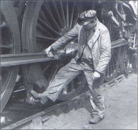
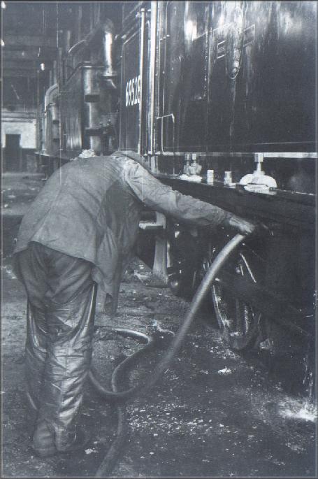
Necessary train household to be done prior to every shift or at the end of every shift.
This is also a part of the job of a railroad man also a career at the railroad company and country independent. Especially when a club or society runs a steam train the mentioned video is to notify you that these works is be done by volunteers of the club or society:
3.00 – The Signal guide
Signalling is one of the important main parts that regulates and maintain safety along the railroad.
Study
3.01 – Signals, the history and importance
The whole run and shift you are driving you have continuously to do with signals telling you the present situation about the track you are about to enter. Signals notifies drivers what to do and how to act and react to avoid any harm and maintain safety. The signals notified in the upcoming chapters contains all basic information about the signal aspects that mainly concerns TS2015.
Other signal related sited are explaining the most deep and technical aspects concerning railway signalling, Refer to Appendix C for the signal related websites in this guide.
If you run a scenario in career Mode the scenario is over when overrunning a signal without request or by order. To request a SPAD press [ TAB ] to activate the SPAD request. When you are running tender first (or backwards) press [ Ctrl ] – [ TAB ] to pass.
Do not use [ Shift ] – [ TAB ] unless you drive MSTS, otherwise the “Steamcommunity” screen appears and you have your SPAD and game-over if driving Career Mode.
Mention: in MSTS the SPAD can not be disabled while in TS20xx, the Free Roam, Standard and Quick Drive mode the “Game Over at SPAD” can be disabled.
Since the very first beginning of railroading signals exist. It started as telegraph signals signalling the telegraph man on events that are about to take place. Telegraph poles were installed parallel to the railroad track. There were no specific rules to keep.
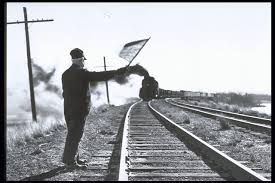
The signal man uses a flag to signal the train. Depending the colour of the flag the driver anticipate on the signal aspect.
Train drivers has to scout the line and anticipate at expected situations. Some countries started with police authorities to maintain safety using flags and time interval system, some had a telegraph man that even scout the line when a train did pass to monitor any damage to rail, sleeper and ballast and other unexpected issues.
The flag system and the time interval system were not reliable enough and men started to experiment with other systems like the High Ball or multiple signals under each other
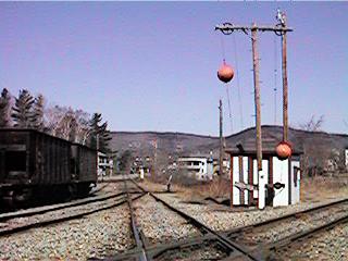
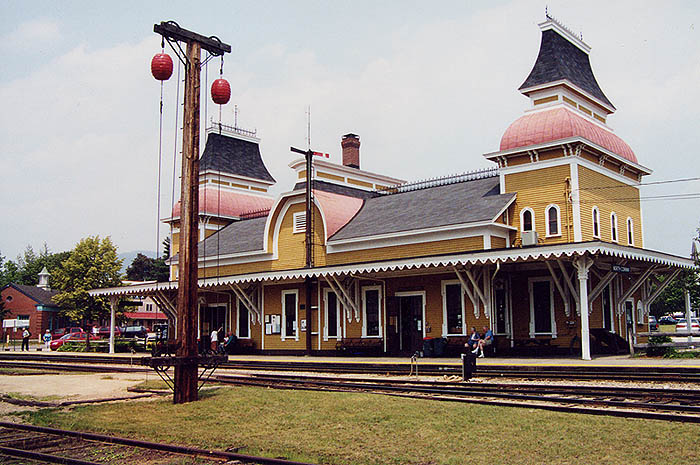
The visibility of signals was often misunderstood by the distance and quite often a train overruns a signal at danger (SPAD) To overcome the issue of visibility, engineers found a solution by using semaphores. The use of semaphores was an off-spring of these of nautical signals to signal an oncoming ship using flags in certain positions.

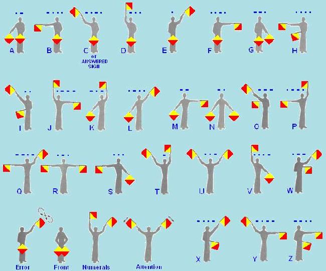
A Navy signals with flags to other vessels
For each position a case-letter was assigned. The need of signalling a ship that heads for the harbour needs information if allowed for entering or not. To overcome the lack of visability lighthouses with a semaphore on the top were installed and became operational.
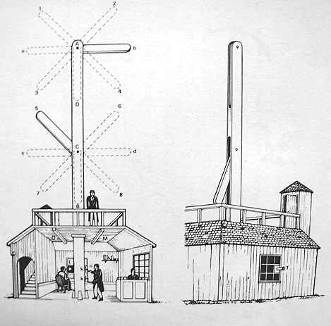
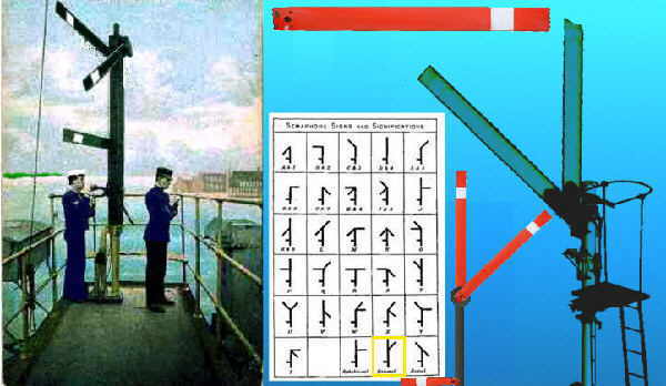
To improve visibility the signal arm of the semaphore were painted red with a white marker. This was an indicator and improved the visibility even more.
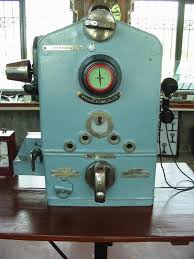
The railroad took the idea to use a semaphore to signal the driver by the position of the signal arm. At night railroads companies installed red, white and green signals, yellow was not very used as signal. Red means stop, white means passing allowed and green means approach and hold at the next signal unless the signal changed into a better signal instead of a danger aspect.
The British reinvention of the train due to the industrial revolution and needed also a standard of safety. The Romans has actually invented the train, but it never came to complete transport revolution. The train is the synonym for mass transportation. Because of the economical weight the train has, safety became the major priority.
All signals started with colours from scratch on. White and red were the first used colours to show an aspect. The semaphores later were equipped with coloured signal lenses. The signal lenses are indicating the red or green colour could be broken easily.
Railroad companies now struggles to find a deep and rigid solution. At the start of the last century engineers of railroad companies tried to find other more reliable solutions.
Experimental signals were testen and also installed prior to the coming of the semaphore. Engineers invented the disc signals showing a coloured disc issuing an particular aspect. Continue the disc signals the USA railroad companies started to cover the disc signals into a wooden cover shaped like a Banjo which became commonly known as “The Banjo”

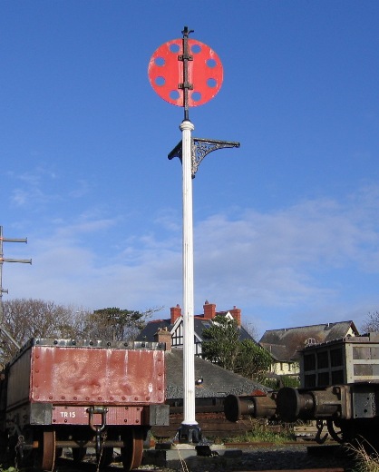
The old disc signal showing a danger aspect. The black and white photo shows a double Banjo signal able to show multiple aspects by a rotating enlightened disc inside the “Banjo”
Disc signals are still in use in several countries like Germany and Britain. The British signal discs are used to show shunting aspects.
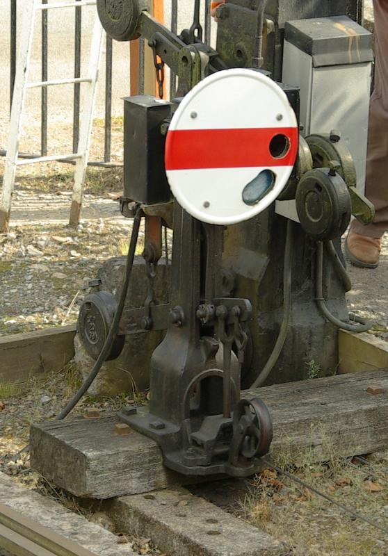

The yellow stripe shows a Permissive signal with a yellow light.
The German main signal is a high placed single or double arm and uses the disc signal as an distance / approach signal these signal are still operational today at several lines and stations.
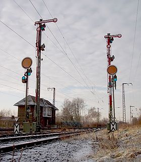
Now when a red lens was broken the light shows a white light indicating the signal indicates the track ahead as a safe block. However on passing this signal at night with a broken glass is actually an adverse signal. Broken lenses gives the driver the ability to misunderstand the signal and overruns it, with disastrous consequences. During this conference, engineers came up with 3 major colours and became standard in the most countries. Even road traffic started to use the same colours with almost the same meaning. The main colours are with either the important common meaning:
- – Red, stop, danger.
- – Yellow, caution, approach.
- – Green, track free no obstructions.
- – White, indicates the signal out of order or simplified clearance aspect at low speed (Shunting)
- – Blue, Stop for shunting engine
Though the last signals is per railroad companies very different.
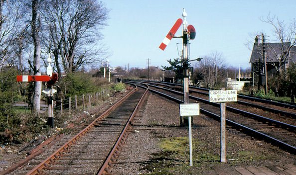
3.02 – Signals, light signals, interlocking
Now the signal arms semaphores became widely spread and used in different ways and shapes. The renowned semaphore shapes are the British and the German signal types. Germany uses upper quadrants only while the BR uses depending the line and area upper and lower quadrants.
The lower quadrant signals “falls” or pointing down when showing a clear aspect. When the signal shows a danger aspect, the arm is levelled horizontally. A counter weight has been installed to level the arm horizontally showing a danger aspect. The Upper quadrants does not need the counter weight but the natural gravitational forces pulls the arm downwards without the need of a counterweight. However behind the arm of a upper quadrant semaphore contains mostly a small counter weight is installed to ensure the arm to function properly.
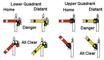
The USA and some countries uses a three position signal showing the main aspects danger, caution and clear. This are the very basic meanings of the three position signals:
- The horizontal arm shows a danger aspect = Stop,
- The diagonal arm shows a caution aspect = caution and expect to stop at the next signal.
- The upright arm shows a clear aspect = clear to pass
More arms underneath each other shows aspects that aims route diverging via designated points. It also regulate the speed of the train unless the speed is given as a stationary speed post. The signals are quite easy to understand and contains very basic regulations.

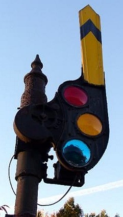
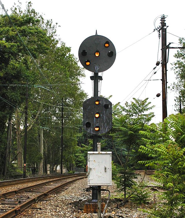

The driver should know the route the train has to go, then the driver anticipate on the proper signal. When a signal shows an aspect that does not fit the route the train has to run, the driver contacts CTC using telephone or radio communication and the route and converging signals will be reset. Though the most semaphore signals are disappeared, three position signals are now taken over by position light signals.

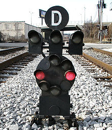
If a combination is lights up, a complete different meaning can be given to the original aspect.
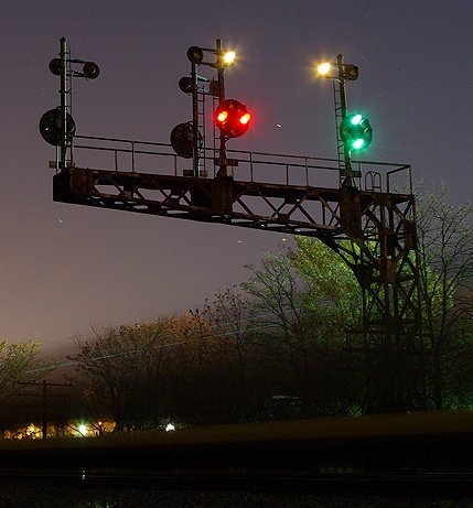
Searchlight signals are one of the best visible signals ever created. At signal boxes the light can be tempered by a switch. At night time searchlight sometimes are too bright to spot. A switch that lead the current via a resistant will reduce the intensity of the light beam.
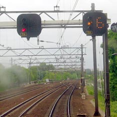

< Dutch signal showing a caution aspect the number shown here is the speed restriction multiplied by 10. The next oncoming signal does not show a danger aspect.
There is no high speed signal given here is not given here instead a white light eliminates the high speed indication.
The second and the third lights shows a green aspect. The train now has to slow down from medium speed to low speed. Later on this system ceased and merged into a more simpler signal system. The signal are now mostly replaced by the modern Dutch standard signals.
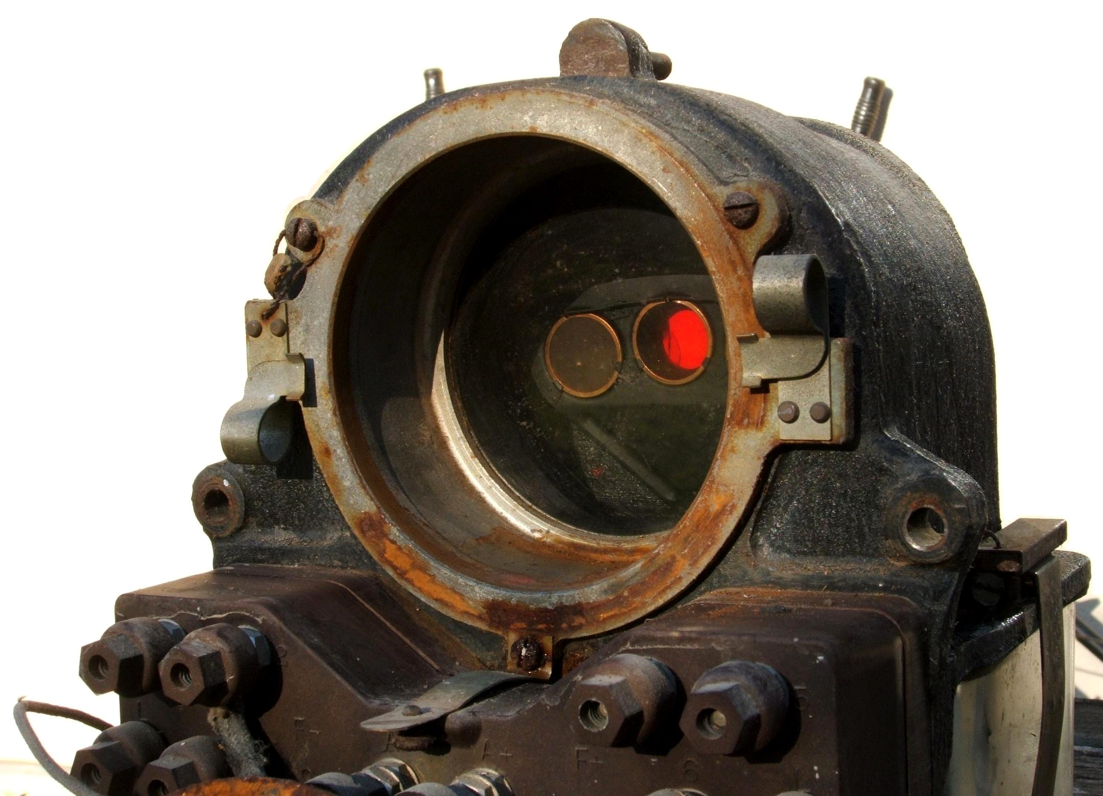
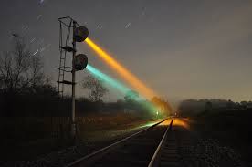
The light beam is highly visible from a far distance.
The 3 colour light mechanic with the small lenses fitted in a half-disc
Mechanical signals are operated by levers pulling a strain, electro-pneumatic or electric.
Signal boxes contains interlocking systems that prohibit failures in signalling and point settings.
A interlocking is quite simple but still complicated. A simple example: When a point is set into a certain direction, a signal that should give an adverse aspects is impossible by the interlocking system. In IT terms when point X is set to direction A the signal in the opposite direction can not show a clear aspect. In other words: if A=1 then B=0.
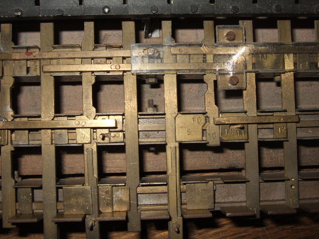
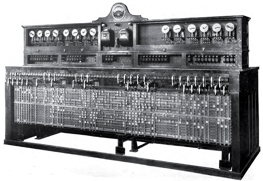
An interlocking device. Notice the rod cabinet. An interlocking system in operational order. Mention the notches that locks other rods
The strains pulled by the levers in the signal box are guided through rollers and guiders along and aside the track. A counter weight mechanical device pulls the strain through rollers and guiders to keep the strain tensioned.
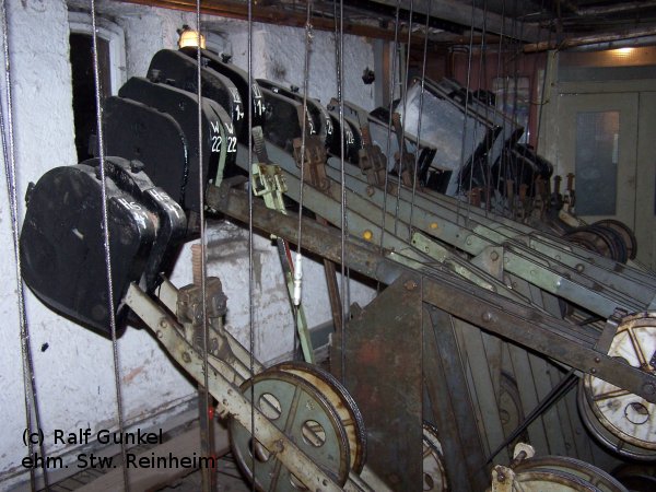
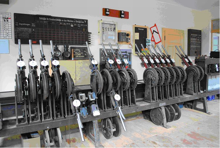

To regain services after WW2, signal boxes were recreated out of available materials at that moment. Old or partly damaged wagons or coaches took over the shelter from signal boxes if destroyed. An example is the bridge signal box that is formed out of former wagons or coaches.

The use of strains and rods is effective in mechanical operation of points and signals. Strains are more flexible but is more inherit to malfunction due to broken strains or malfunction tension devices. Rods however are more rigid but more heavier to operate in the winter period.
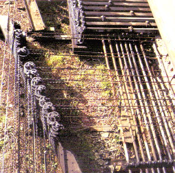
3.03 – Modern signalling and steam locomotives
303 Modern signalling and steam locomotives
The safety technique does not stop and the preserved steam locomotives needs to stay equal to the standards of today. In some occasions it is hard to catch up with these standard rules of safety and steam locomotives has to be adapted to these modern standards as well.
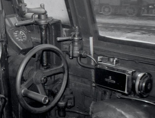

An air cylinder will force the regulator to cut off when the emergency brake kicks in, but will not close the regulator completely to keep some steam in the cylinder blocks.
Indusi is a point-to-point signalling transmission, This system was already present in the steam era and was build at every steam locomotive throughout Germany. A powered magnet with a single frequency or multi frequency was beamed up to a magnetic receiver that was installed at the engine or tender. The signal just knew three different frequencies:
- 500 Hz for distance or approach speed limiter
- 1000 Hz at distance and approach at main signals
- 2000 Hz for a overrunned signal causing an emergency stop
This system is a proven system and since the 30’s installed at German engines.
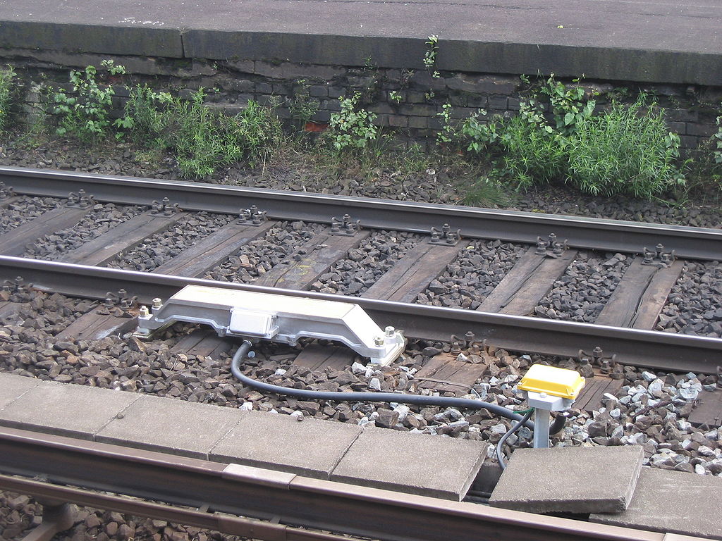
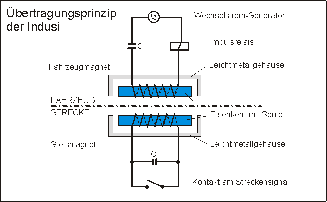
Trains has to pick up the signal from the rail magnet into the receiver magnet and gives a lamp indication at the Indusi device.

An acoustic signal will sound when you overrun an activated track magnet. Within 4 seconds, press [ Q ] or drag the “Freigabe” (Acknowledge) knob to interact on the given signal, otherwise the emergency brake kicks in.
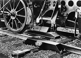
An electric wire leads to the Indusi device in the cabin itself.
Now you have to (re)act on the acknowledgement [ Q ] in order to avoid an emergency brake within the range of 185 meter from the main signal. Be sure you slow down the train within reasonable limits of comfort. Ensure the speed has drop down to stop within the required distance. If you have not respond to the second magnet warning will activate the emergency brake still.
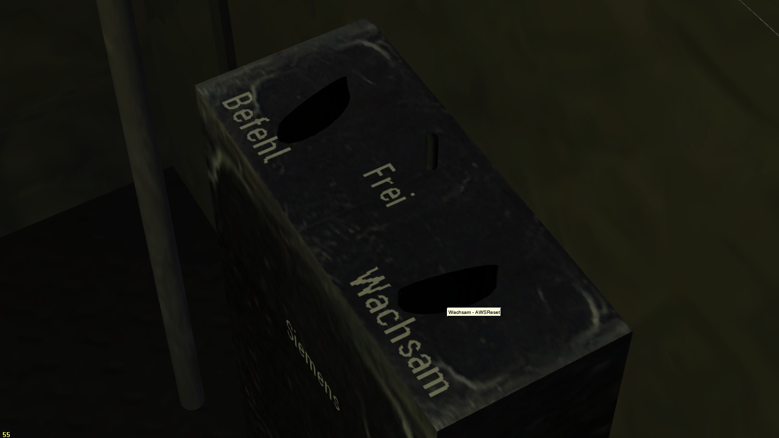
It can also be used on a malfunctioning Indusi. Normally you have to report the malfunctioning Indusi system.

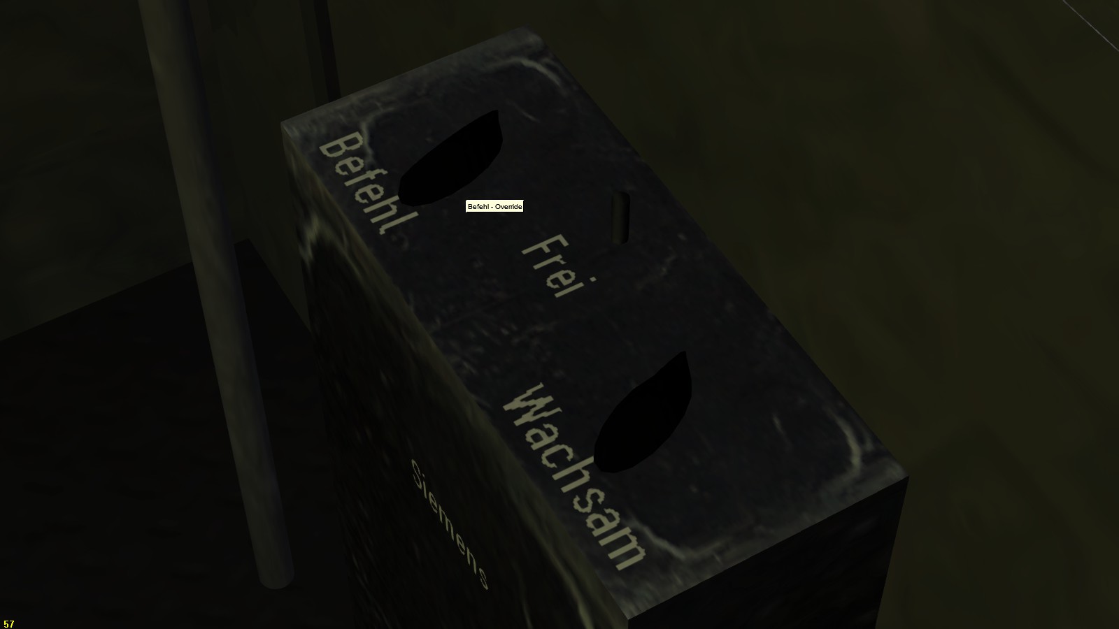

When a Indusi magnet is reached after the distance warring at 1000 Hz a second 500 Hz signal is given to remind the driver to stop at the oncoming main signal. The Indusi indicator shows a red lamp showing 500 (Hz).
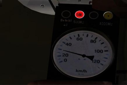

A new installed Indusi / PZB receiver magnet that fits the modern standards of today’s safety rules. The magnet is installed at the tender.
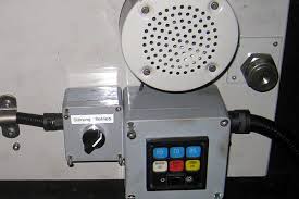
The British Rail uses a similar sort of warning system that translates a signal into the cab a same sort of point to point signal transmission. But it still has their differences as well. The AWS is in widely used in Britain, but is very limited in signalling the driver. The signal only shows a yellow/black rose after acknowledging the buzzer signal. When the driver does not respond to the buzzer within 4 seconds the emergency brake kicks in. When the buzzer is sounding press [ Q ] to acknowledge.
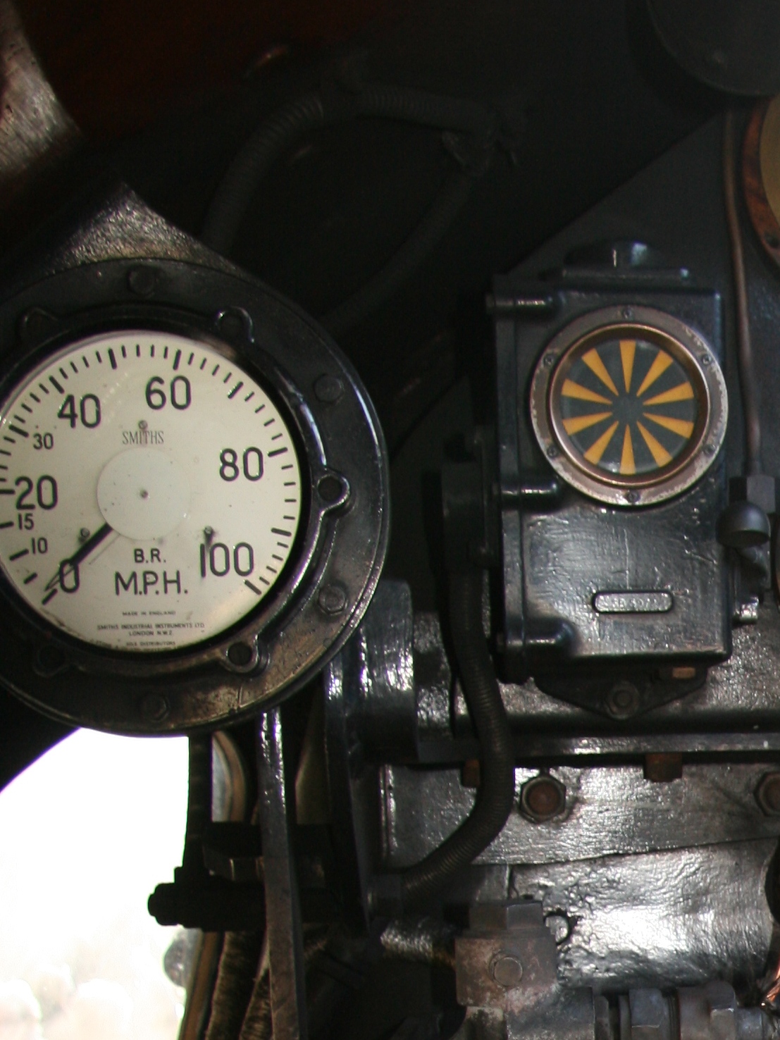
TPWS is not working in TS2015 yet, but the AWS system is operational. On passing a beacon in between the rail a acoustic signal is sounding. Depending the type of sound which is a bell or either a loud buzzer which demands a reaction to operate the AWS system by press down a lever. The AWS visible signal shows a black/yellow rose to remind a caution or restriction.
The caution warning indicated a danger aspect ahead. but can not show other aspects.
The USA started with cab signalling early in the 20’s of the last century. A frequency signal was given in both rails of the track. Each rail has a different frequency. When a train passes the track a receiver “sucks” the signal out of the rail and leaving the rail behind without the frequency signal.


Two different frequencies are beamed the variety of frequency signals is objective to a designated speed limitation. The signal beamed from out of the rail itself has been “sucked” into a receiver that transmits the signal to and through a range of electronic filters that detects the frequency. When a certain frequency is measured and recognized, a designated cab signal lights up and if necessary with an acoustic signal as well. If the left rail beams out a frequency signal of 40Hz and the right rail beams a frequency signal of 80Hz is equal to a certain speed limitation depending the system, for example: 60 Mph.

The board computer expects these signals as mentioned. When the train should run with the same signal but in opposite direction the frequency signal does not change but the train direction is. The board computer espect the signals in the right direction but does not get the right information and blocks the trains driving path, but could give a limited clearance aspect or a restricted aspect for slow speed (15 Mph for example).
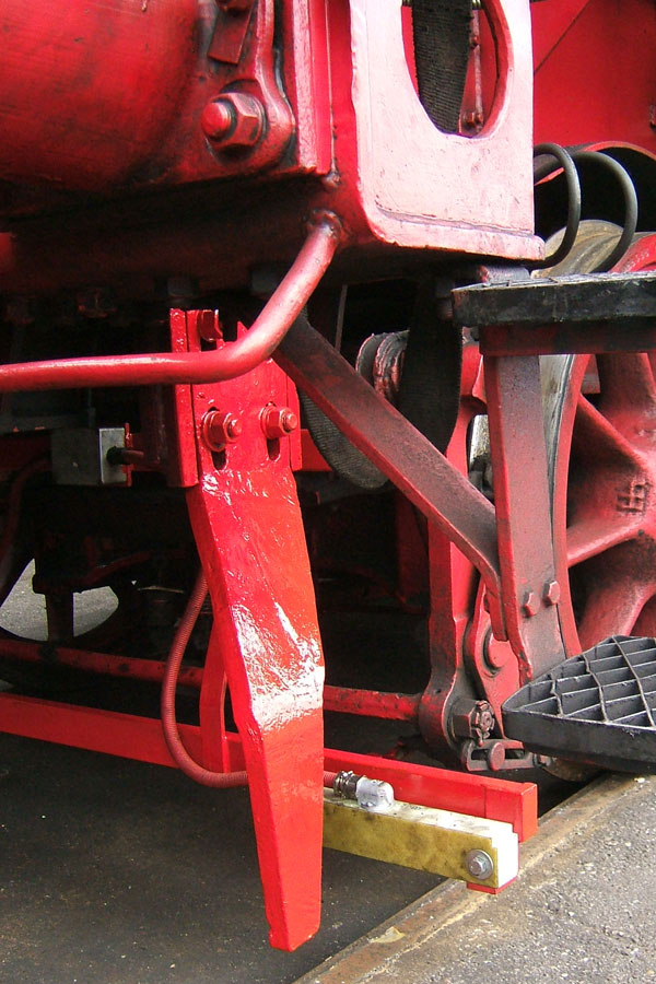

3.11 – USA NORAC light signal aspects
All the DLC and 2rd party add-ons contains signals as originated. The regulations still remains the same as defined by the original rules, regulations and restrictions at they has been governed by the particular country. Each country has their own restrictions and rules.

Taking a closer look and all the signals after study are basically the same and quite equal to each other, but the design of appearances of much different, the aspects remains basically the same
All the common and most basic signal aspects are shows as far as necessary and needed within TS2015. It should be hugh to pay attention to all signal systems in the world. while the most signalling aspects around the world are plainly based at the signal system of the heritage signal and rail system of the British Railway companies
First important issues what you need to know how to drive on signals.
There are 10 different types of signals.
- Main signals
- Approach and distance signals
- Speed signals
- Shuntong signals
- Temporarely signals (maintenance, track work, infrastructure, etc)
- Hand signals
- Stationary signals (whistle posts, electrical traction, stopping markers. mileage / kilometre posts, etc)
- Acoustic signals, (Bell, whistle, horn, typhoon, hand whistle, explosion signals)
- Cab signals.
- Radio / GPS signals (related to cab signalling)
This chapter mentions the signals as they are in use and regulated by the MORAC rules which is covering all rules from every railroad company throughout the USA and Canada
____________________________________________________________________________
Proceed Not exceeding normal Speed.
USA: NORAC 281
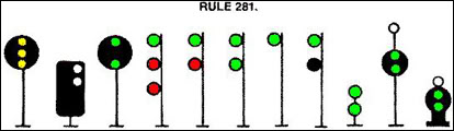
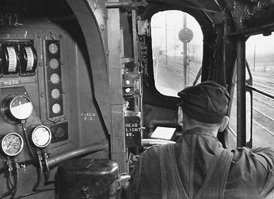
A driver of a GG1 receives a Clear Aspect
____________________________________________________________________________
Proceed approaching the next signal at limited speed.
USA: NORAC 281b
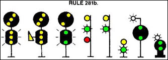
____________________________________________________________________________
Proceed at Limited speed until entire train clears all interlocking and spring switches,
then proceed at normal speed.
USA: NORAC 281c
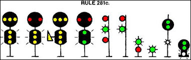
____________________________________________________________________________
Proceed Approaching next signal at medium speed. (Max. 30 Mph.)
USA: NORAC 282:
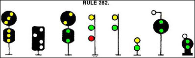
____________________________________________________________________________
Proceed prepared to stop at the second signal. Trains exceeding Limited Speed must begin reduction to limited speed as soon as the engine passes the Advanced Approach Signal.
NORAC 282a:
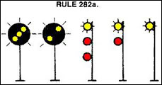
____________________________________________________________________________
Proceed at medium speed until entire train clears all interlocking and spring switches, proceed at normal speed.
USA: NORAC 283:
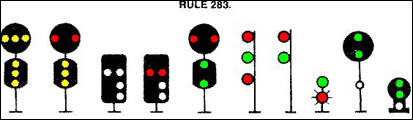
____________________________________________________________________________
Proceed approaching the next signal at Slow Speed.
Trains exceeding Limited Speed must begin reduction to limited speed as soon as the engine passes the Approach Signal
USA NORAC 284:

____________________________________________________________________________
Proceed prepared to stop at the next signal.
Trains exceeding Medium Speed must begin reduction to Medium Speed as soon as the engine passes the Approach Signal.
USA NORAC 285:

____________________________________________________________________________
Proceed prepared to stop at the next signal
Trains exceeding Medium Speed must begin reduction to Medium Speed as soon as the Medium Approach signal is clearly visible.
USA NORAC 286:
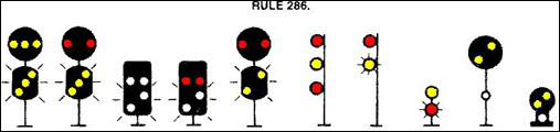
____________________________________________________________________________
Proceed at Slow Speed until entire train clears interlocking limits or turnouts, then proceed at Normal Speed.
In CSS territory with fixed automatic block signals, trains not equipped with operative cab signals must approach the next signal at Medium Speed once they have left interlocking limits.
USA NORAC 287:
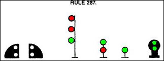
____________________________________________________________________________
Proceed prepared to stop at the next signal. Slow Speed applies within interlocking limits or through turnouts, then Medium Speed applies.
USA NORAC 288:

____________________________________________________________________________
Proceed at Restricted Speed until the entire train has:
1. Passed a more favourable fixed signal. or
2. Entered non-signalled DCS territory. or
3. Passed a location where a more favourable cab signal was received.
USA NORAC 290:
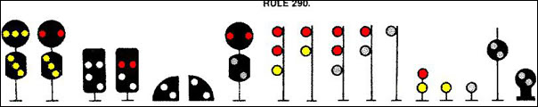
____________________________________________________________________________
Stop, then proceed at Restricted Speed until the entire train has:
1. Passed a more favourable fixed signal. or
2. Entered non-signalled DCS territory or
3. Passed a location where a more favourable cab signal was received.
Where a letter G (grade marker) or a letter R (restricting marker) is displayed in addition to number plate as part of these aspects, freight trains may observe the signals as though restricting, Rule 290, were displayed.
USA NORAC 291:
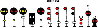
____________________________________________________________________________
Stop before the signal.
The signal is not allowed to pass unless the signal can not be cleared. The Signaller will hand over a confirmed and signed warrant to pass the signal at danger. When the signal is too far from the signal box, the driver contacts the signalman to receive clearance by telephone or radio.
USA NORAC 292:

____________________________________________________________________________
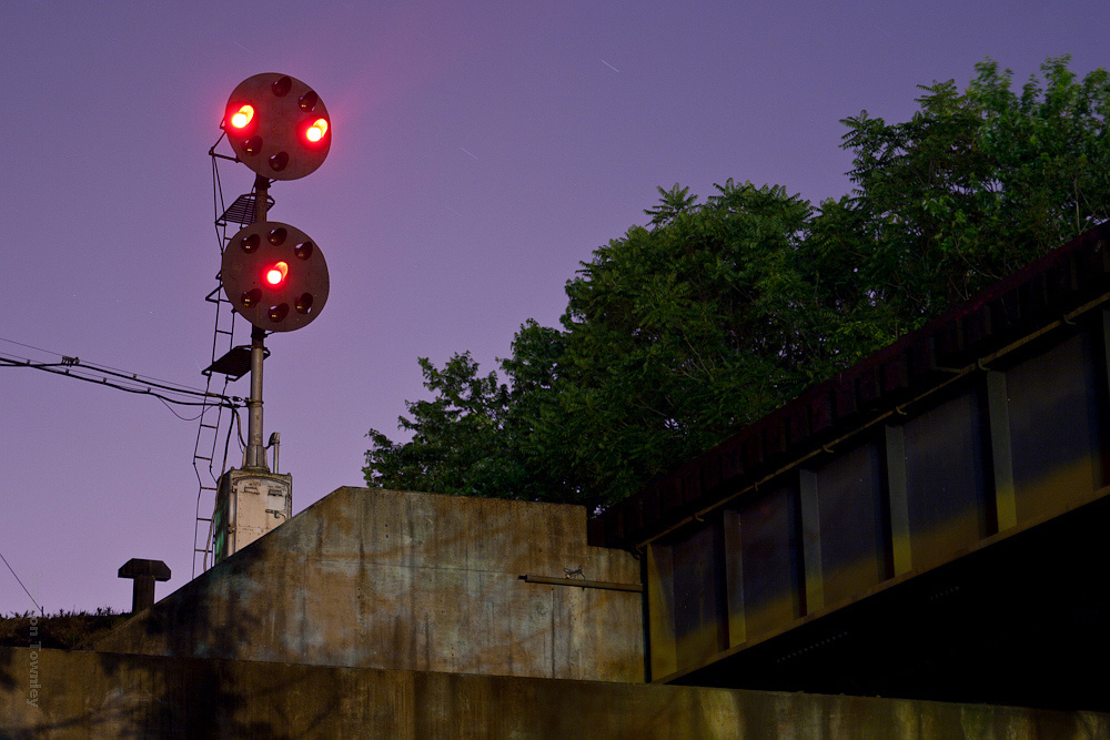
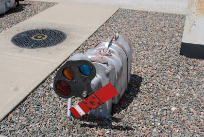
3.12 – USA NORAC permanent signal aspects
312 USA NORAC permanent signal aspects
The USA signals are all combined in the NORAC rule book. This rulebook is valid for all railroad compagnies in the USA and is governed by the federal law. The rules remains the same for all compagnies, but the signal lay-out can be very different. However the signals will have the same regulations and restrictions when the NORAC rules are applied.
____________________________________________________________________________
Proceed prepared to operate at posted speed through permanent speed restriction.
USA: NORAC 296

____________________________________________________________________________
Approach the Speed Limit Sign at a speed not exceeding the speed posted on the Approach Speed Limit Sign.
USA: NORAC 296a
____________________________________________________________________________
Proceed at speed posted on the Approach Speed Limit Sign.
USA: NORAC 296b
____________________________________________________________________________
____________________________________________________________________________
If routed to affected track, approach the Speed Limit Sign not exceeding the speed on the Diverging Approach Speed Limit Sign.
USA: NORAC 296d
____________________________________________________________________________
If routed to affected track, approach the Speed Limit Sign not exceeding the speed on the Diverging Approach Speed Limit Sign.
USA: NORAC 296d
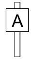
____________________________________________________________________________
____________________________________________________________________________
Proceed prepared to stop at the Stop Sign.
Slow down and be prepared to stop at the oncoming stop posts 297a.
USA: NORAC 297
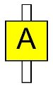
____________________________________________________________________________
Stop, unless permission is received.
Permission in the case of TS2015 can be given by pressing [ Tab ] or by a notification,
then proceeding according the given order or notification is then allowed.
USA: NORAC 297b
____________________________________________________________________________
____________________________________________________________________________
Proceed not exceeding 30 MPH until passing a Working Limits Resume Speed Sign.
If otherwise instructed by the employee in charge maintain the speed limitation of 30 Mph.
is not to exceed.
USA: NORAC 297b
____________________________________________________________________________
Resume speed after the entire train has passed the Working Limits Resume Speed Sign.
USA: NORAC 297c
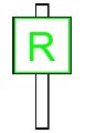
____________________________________________________________________________
____________________________________________________________________________
Proceed approaching the next signal at limited speed.
USA: NORAC 298
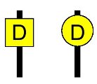
____________________________________________________________________________
Visual reminder to push-pull trains that applies NORAC Rule 504 to station stops made at this station.
The following restrictions do not apply to trains that have cab signals in service
for the direction of movement, or that have experienced a cab signal failure in Rule
These signal posts are located at or near the end of passenger stations in blocks between distant signals and home signals and mentioned for push and pull train operations.
The use of cab signals is actually disengaged and not in service.
The maximum speed is set at 30 Mph and only valid for Push and Pull trains
USA: NORAC 298a
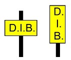
____________________________________________________________________________
3.13 – USA NORAC Cab signalling
Cab signalling was already mentioned in this guide. But due to some DLC’s that contains cab driving signalling aspects it is obvious to pay attention to the rules and regulation as well.
Some steam locomotives like the PRR K4 and the UP FEF-3 contains a cab signal display.


The PRR shows white light Cab signals that are equil to the position lights the PRR uses.
However the signal lay-out does noty show any color.the NORAC rules remains the same.
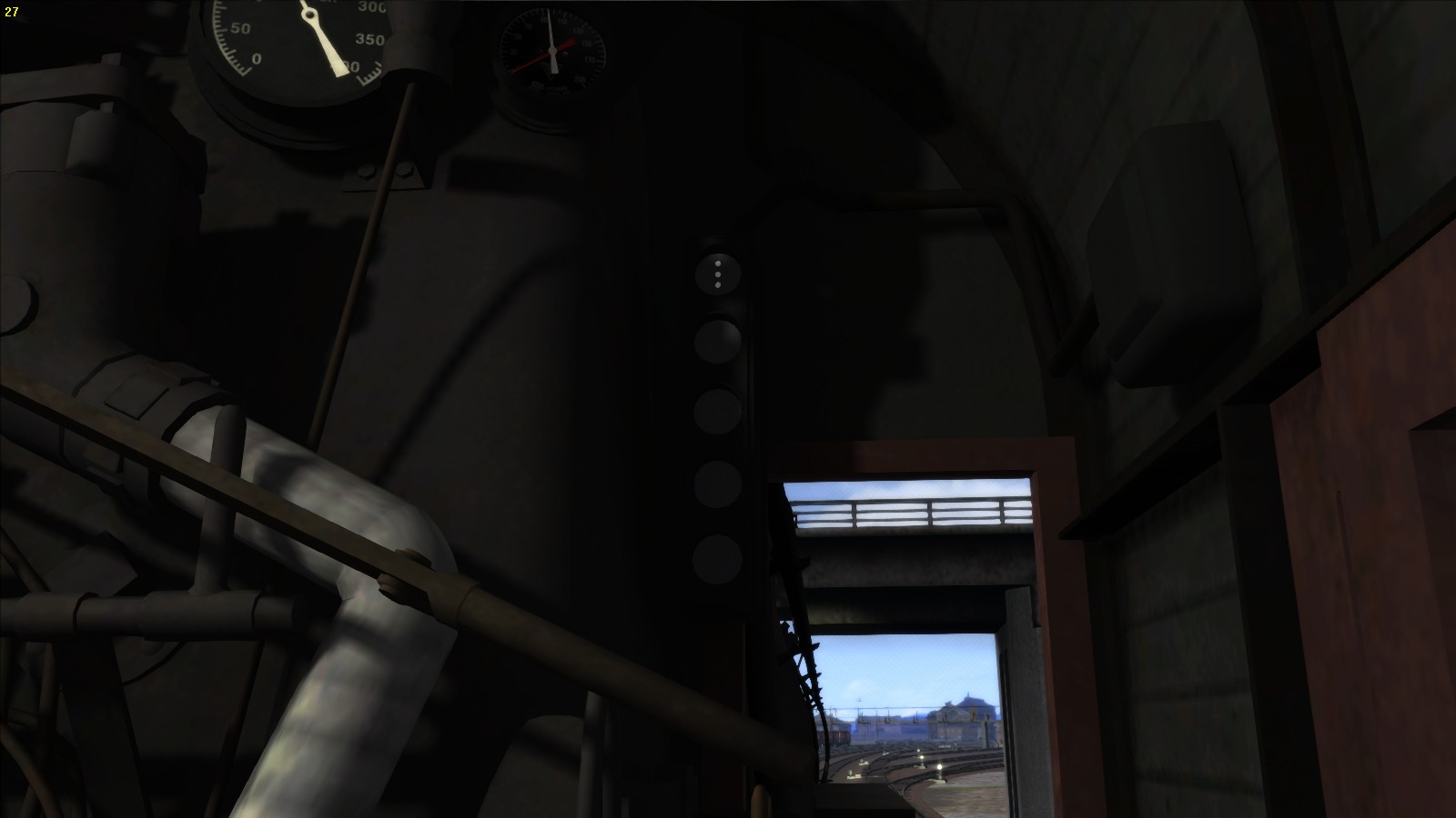
On track clearance the display will show a PRR style “Clear” aspect.
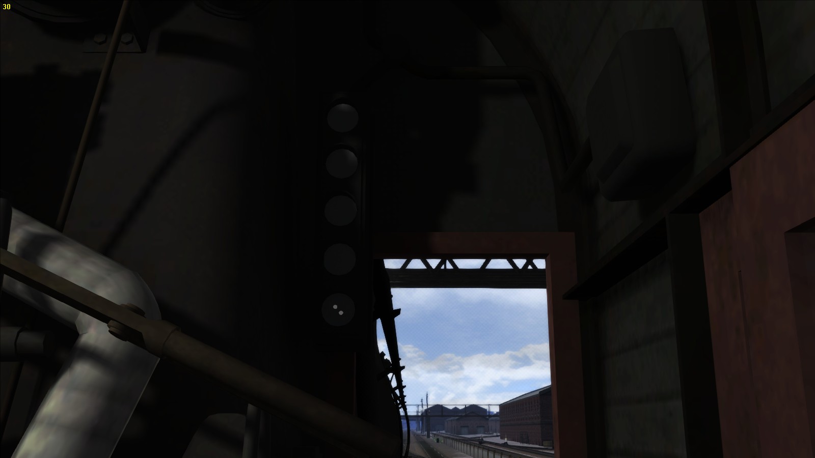
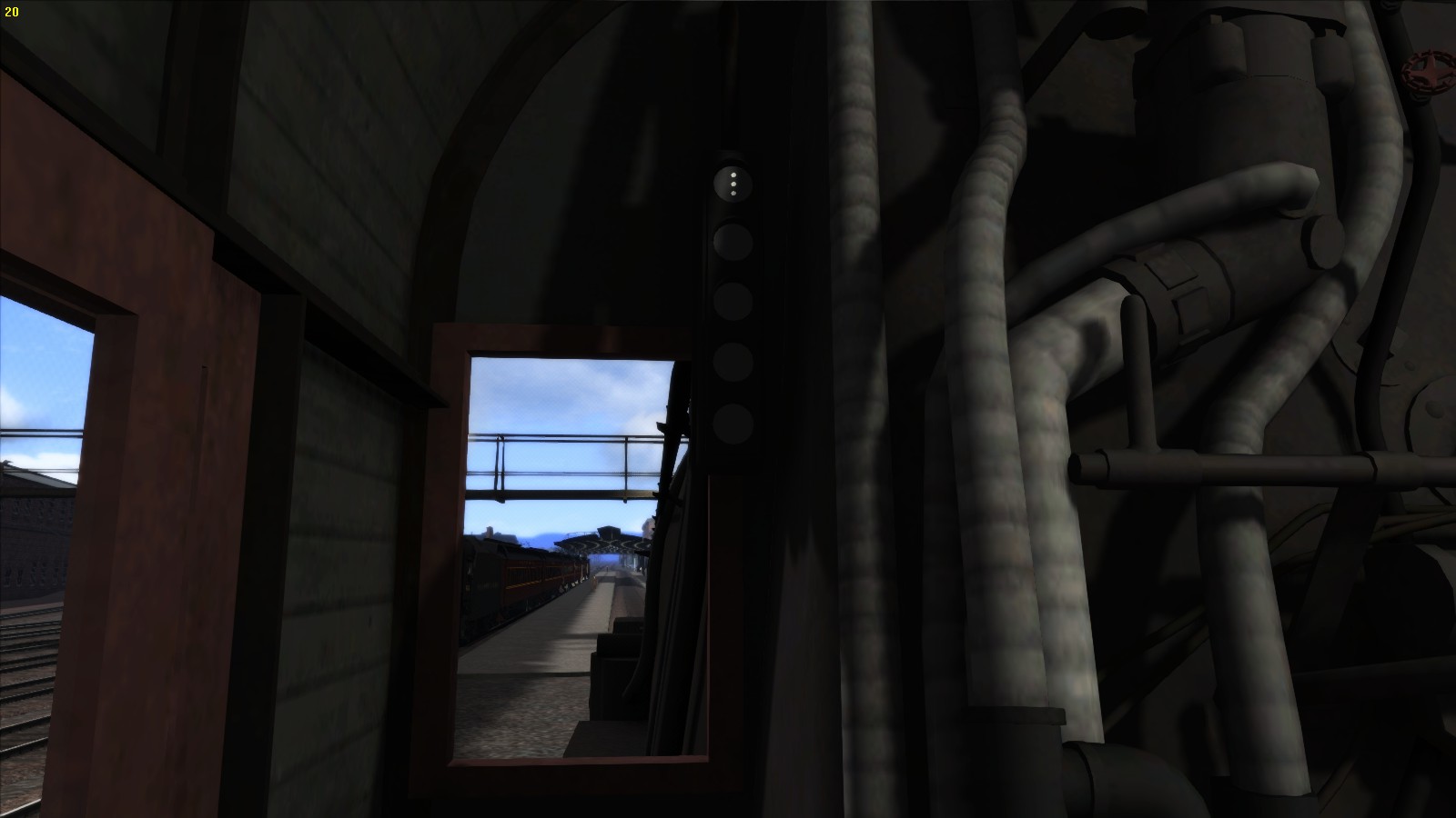
The principal is actually quite simple and there are different reasons to have cab signalling.
- The driver reminder of the last shown signal aspect.
- The espected signal aspect
- The system can kick in if the driver fails to do so.
- The track speed
- The signal speed
In the present advanced systems the target distance is mentioned as well.
Modern engines does contain a SDU Display that shows two signals and two numeral displays.
These displays shoews either the numbers in different colors wither different meanings and targets. These numeral displays are often not present at steam locomotives.
An SDU Display in an Acela cab:
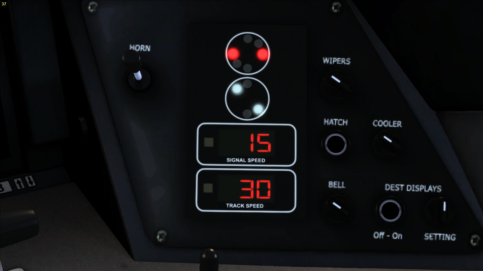
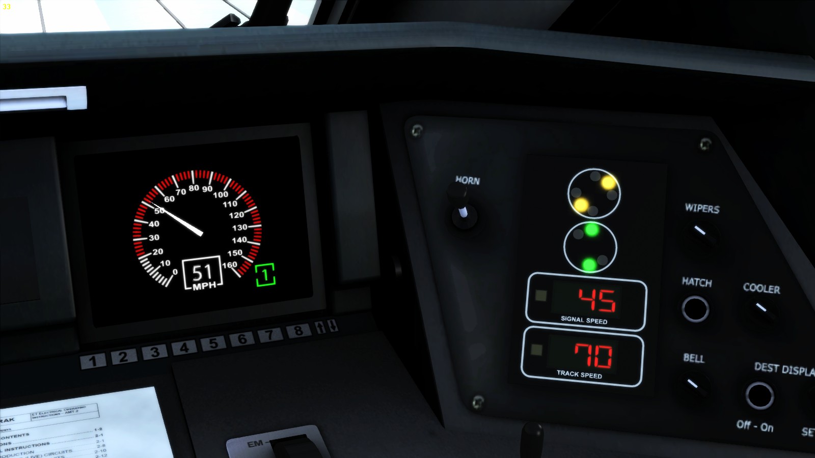
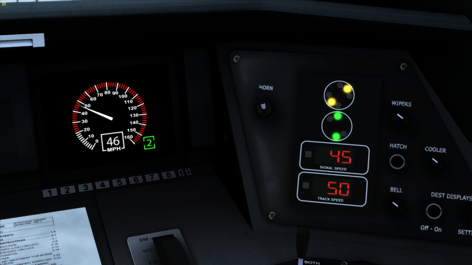
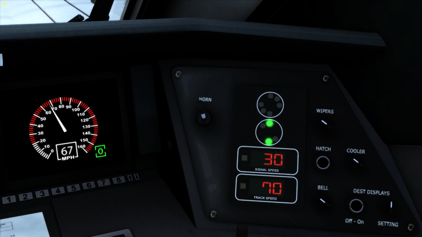
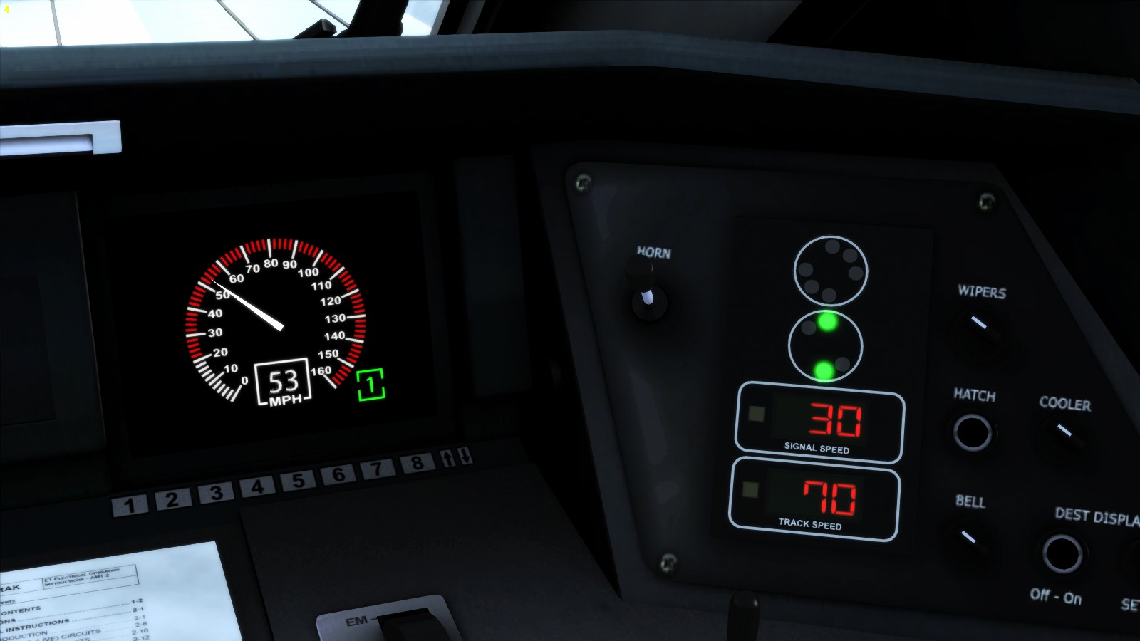
____________________________________________________________________________
2
Refferes to:
- NORAC rule 281: Clear
Definition SDU Display: The center speedometer numbers are mentioned in green

____________________________________________________________________________
3
Refferes to:
- NORAC rule 281: Clear
- NORAC rule 281a: Cab Speed
- NORAC rule 281b: Approach Limited
- NORAC rule828: Approach Medium
Definition SDU Display:

____________________________________________________________________________
4
Refferes to:
- NORAC rule 281b: Approach Limited
- NORAC rule 282: Approach Medium
- NORAC rule 282a: Advanced Approach
Definition SDU Display: A green band 0 to 45 MPH
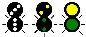
____________________________________________________________________________
5
Refferes to:
- NORAC rule 281b: Approach Limited
- NORAC rule 282: Approach Medium
Definition SDU Display: A green band 0 to 45 MPH
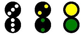
____________________________________________________________________________
6
Refferes to:
- NORAC rule 285: Approach
- NORAC rule 284: Approach slow
- NORAC rule 283a: Approach Medium
Definition SDU Display: A green band 0 to 30 MPH

____________________________________________________________________________
8
Refferes to:
- NORAC rule 287: Slow clear
- NORAC rule 288: Slow Approach
- NORAC rule 290: Restricting
- NORAC rule 291: Stop and proceed
- NORAC rule 292: Stop
Definition SDU Display: A green band 0 to 20 MPH, Lunar White band at 0
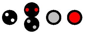
____________________________________________________________________________
9
Proceed apporaching the next signal at normal speed.
Refferes to:
- NORAC rule 292: Stop
Definition: A green band 0 to 60 or 80 MPH

____________________________________________________________________________
3.21 – BR: Shunting signals and speed signs
314 BR Shunting signals and speed signs
Shunting signals or dwarf signals are destined to guide shunting movements only. Every engine can be set for shunting purposes, but special engines are better equipped to do the shunting job.

The old style shunting signals
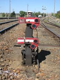
To regulate safe shunting, special signals are installed to guide shunters properly on their job. However the speed is low and restricted, an accident can still occur during shunting causing a derailment.
____________________________________________________________________________
Absolute shunting signals:
When a shunting signal shows a red beam on a white disk or a red/white and either red/red light combination, then any shunting movement beyond the signal is strictly forbidden in any circumstances. Unless the signal is malfunction, then the proceeding restriction is given by warrant or radio order directly from the signalman or CTC
- A red light horizontal next to a white light.
- Two red lights horizontal next to each other.
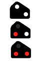
Unlike other railroad companies. the route which are set could show a cleared shunting aspects, however the meaning of a cleared shunting signal does not tell the driver to proceed.
A white shunting signal indicates the points are set instead of permission to proceed.
____________________________________________________________________________
Permissive shunting signals
When a shunter signal shows a yellow beam on a white disk or a yellow/white and either yellow/yellow light combination you are allowed to maintain shunting in certain circumstances.
When you have to continue to shunt to another yard, siding or headshunt directly ahead of you without crossing or endangering the mainline you are then allowed to continue.
- A yellow light horizontal next to a white light.
- Two yellow lights horizontal next to each other.
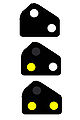
The yellow shunting signals are in use at sidings or headshunts when another siding or yard is connected which is not endangering the mainline. The driver is allowed to pass the yellow signal when the points are set to another yard or siding. The driver has to scout the track after all.
____________________________________________________________________________
Shunting signals showing a clear aspect but only tells the driver the points are set correctly.
However a clear to go is not mentioned when the shunting signal shows a white light or a red arm on a white disk that is equal to a upper or lower quadrant position.
The shunting disk signals is not to be mixed up with a repeater signal. The difference between a repeater signal and a shunting signal is the position of the signal. A shunting signals is always positioned close to the ground or underneath a main signal.
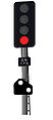


____________________________________________________________________________
Diverging Shunting Signals
Shunting signals covering a point can also cover diverted routes that leads to different directions of shunting. In this case more disks are installed underneath each other the lower shunting shows then a point clear aspect when the route is set into a diverted direction.
____________________________________________________________________________
All the routes which are recreated on real routes does have also the original signalling aspects as close as possible like the original route. Most aspects remains the same as they appear along the route.
Speed announcement posts
A Speed announcement post is a triangular shaped speedpost with a yellow edge at a white plate. in the centre of the plate a number is visible. The number represent the speed in miles per hour. Now you have to slow down and at the next speed post you are not allowed to exceed the restricted speed limit.


____________________________________________________________________________
Absolute speed posts
After the announcement of reducing speed you will have the second speed posts which is an absolute speed posts. from this point the restricted maximum speed might not be exceeded.


Speed posts with a double number refers to the difference between passengers trains and freight trains. The upper number is valid for freight trains. The lower number is valid for passenger trains.
____________________________________________________________________________


Speed posts for diverging routes
The speed post containing an arrow or letter are referred to a certain designated direction. When diverted the given speed may not be exceeded as well.


____________________________________________________________________________
3.22 – BR: RETB Radio token signalling aspects
322 – BR RETB Radio token signalling aspects
The northern regions in Scotland at lines between Inverness – Wick / Thurso, Fort William – Mallaigh (The Jacobite) and some other lines has RETB signalling to regulate low frequent train traffic The west Highlands between Fort William and Mallaigh over Glenn Finnan contains this type of signalling.
The basics of RETB are mentioned in this chapter how to deal with the signalling system of RETB. Entering a station protected with the signalling below will demand the driver to request a radio token. This unique number is a special number and cannot be given twice. the radio token will be attached to the train that needs to drive on a particular route between certain points. The radio token is available in a screen and activated. As long as that particular radio token identification number is valid. No other train can enter the area with a second number or another identification number (Radio Token)
When entering the first station that is protected with the signalling below the driver only can proceed after the release of the first radio token and then in sequence when the second token is received and activated.
However the whole system is actually based in the old magnetically token system which is almost working in the same way but mechanical . The signaller received a token that needs to be entered in a “reader” that enables the signalman to set points and signals.
When passing the distance marker get prepared to stop at the next signal (marker).


< A red light is persisting having the same purpose as the yellow flashing light indicating the point(s) is(are) set correctly and safe to pass.

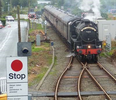
The oncoming diagrams below shows the working of the RETB style signalling. Mention the sequence of signalling as they appear when approach a station or yard protected by RETB signalling

The RETB signalling at a single line with a small station.
The RETB signalling at a station with a loop.
The RETB signalling covering a point or junction.
____________________________________________________________________________
3.23 – British Rail signal aspects
Signals of the British Rail is the oldest signal system in the world. though the signalling system is very basical and quite simpel to understand. Some signals needs special attention.
Adjust the speed of your train when you are driving correctly according the given signa laspect.
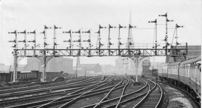
____________________________________________________________________________
1
Danger aspect: Stop before the signal
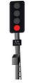
Semaphore signal:
Upper quadrant and lower quadrant showing a horizontal red arm and either red light.
Semaphore arm with black ring to indicate the aspect is valid for freigh trains only.
Diagram of ringed semaphore signals valid for freight trains
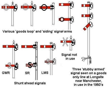
On approaching a signal that indicates a danger aspects, the signal could change aspects into a proceed at low speed aspect when a route is set into a diverted direction. You then are allowed to release the brakes and continue to proceed with resticted speed untill the poin(s) is (are) cleared by your train you drive, then normal track speed is allowed.
____________________________________________________________________________
2
Repeater signals indicaties a Danger aspect at the oncoming main signal. Mostly these signals are situated at blind curves and at the beginning of platforms


____________________________________________________________________________
Distance or approach signal: Caution, prepare to stop at the next signal.

Semaphore signal: Upper and lower quadrant yellow arm in horizontal position.
As single signal post on lines with low traffic and simplified signal system:

____________________________________________________________________________
Distance or approach signal: Double yellow: Prepare to stop at the second signal;
This signal is given at lines with high speed. The signal indicates a pre-caution aspect Drivers now has to slow down slowly and earliy and to get prepared to stop at the second signal. The first oncoming signal wil show a single yellow aspect.
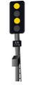
____________________________________________________________________________
Repeater signals indicaties an approach or distance aspect The only differance is the fish tail end tro indicate the approach of an approach or distance signal.

____________________________________________________________________________
Clear aspect: main signal

Semaphore signal: Upper quardrant: diagonally postioned red arm pointing upwards with a green light.
Semaphore signal: Lower quardrant: diagonally postioned red arm pointing downwards with a green light.
____________________________________________________________________________
Clear aspect; Distance or apporach signal
Semaphore signal: Upper quardrant: diagonally postioned yellow arm pointing upwards with a green light.

Semaphore signal: Lower quardrant: diagonally postioned yellow arm pointing downwards with a green light.
____________________________________________________________________________
Repeater signal showing an oncoming clear aspect


____________________________________________________________________________
Route diverging aspects: A Green signal with a white litted stripe on top of the signal
Diagram with examples:
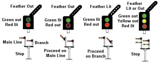
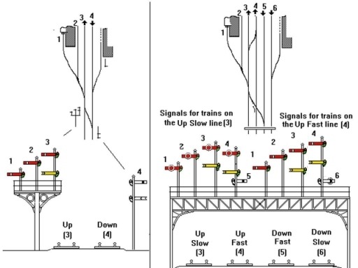


Route diverging uasing a double signal on a rack. The green positioned light indicating the route diverging to the right or to the left depending the position of the light aside the yellow lights.


Route indicators showing a number mainly at station or yard entrance signals indicated the route which is set to a certain tracknumer corresponding with the number shown at the signal. The letter indicates a route set to a certain city or village, mostly the first letter of the city name.


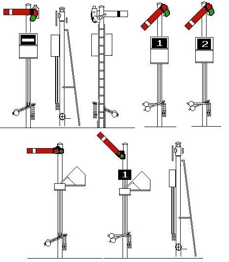
Repeater signal showing the clearance onto a diverted direction
3.24 – British Rail Headcodes
324 British Rail Head codes
The typical head codes the British Rail uses is unique in the world. The system is in use since around 1850 based on the former Time-Interval block system. This sophisticated system enables the signallers to verify the train to the time time from a far distance. On proper use the signals and points can be set accordingly the routing of the train.
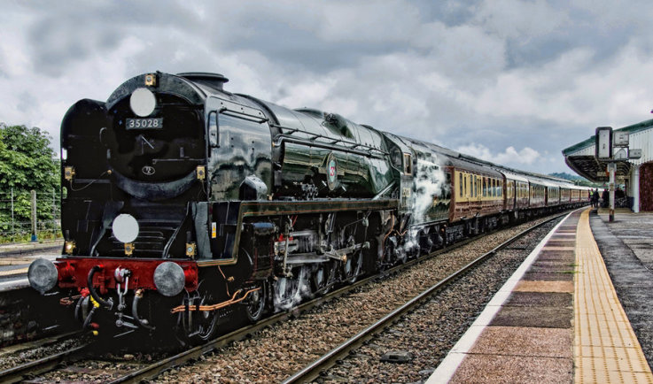
Lamp codes and disc codes are typically British and in use since about 1850
Depending the locomotive you use in train simulator (TS2015 only) you can change the head codes and lamp codes. For every engine you have to refer to the manual in order to have he proper head codes on your train. Steam locomotives migh have the possibility to change during the run. Head code change at the 4MT and 6MT Advanced class of Just Trains can be achieved by using the key combination by pressing [ Ctrl ] and:
- [ 1 ] left-under,
- [ 2 ] Middle-under,
- [ 3 ] right-under and/or
- [ 8 ] top light.
[/b]
[/list]
Some Advanced British RSC/DTG engines uses instead of the [ 8 ] the [ 4 ]
The sequence is different:
- [ 1 ] Top-light
- [ 2 ] Left-under
- [ 3 ] Middle-under
- [ 4 ] Right-under
[/b]
[/list]
The diagram below shows the classes for use of lamp codes at steam locomotives; Using the lists above will give the right lamp codes on the train you drive.
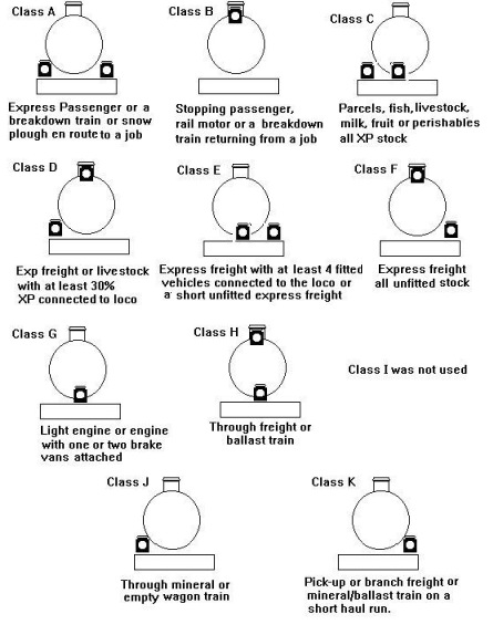
This creates the ability to “change” your head codes during the run of a scenario. Of course, lamp codes should be set when the engine is not rolling. the engine crew does not change the lamps during a run.
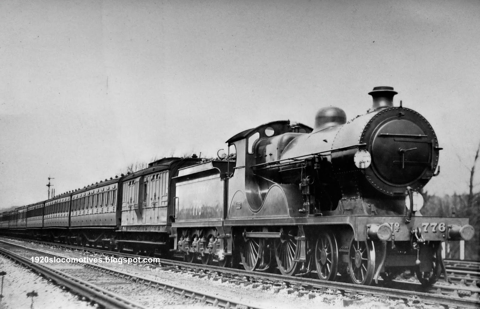
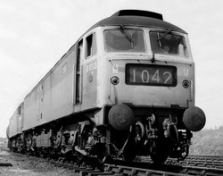
Lamp codes and disc codes are part of the standard British Rail signalling aspects.
With the coming of absolute block signalling, the class-based head codes allowed signallers to identify and regulate trains properly. However on some busy lines, particularly busy suburban ones, the head code denoted the route of the train rather than the class of train. In these areas junctions were complex and timetables were intense: it was more important that signallers routed the trains correctly than regulated trains by class. This was prevalent in the south of England, where companies used six headlamp positions to show the route of train. Some companies had their own code format which led to some confusion where trains from one company ran onto other companies’ lines.
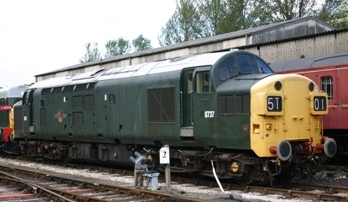
For operational reasons, certain trains have priority in running. To help operating staff, they are grouped into classes; these were formerly identified using letters. When the letter groups were replaced by numerals on 18 June 1962, the classifications became. According to the list you can group your trains and set your head- and/or head codes
- Class A: Express passenger, newspaper, or breakdown train; express diesel car; snow plough on duty; light engine proceeding to assist disabled train.
- Class B: Local and regional passenger services, branch passenger or “mixed” train; rail motor (loaded or empty); ordinary passenger or parcels diesel car; breakdown train not on duty.
- Class C: Parcels, fish, fruit, livestock, milk or other perishable train composed entirely of vehicles conforming to coaching stock requirements; empty coaching stock (not specially authorised to carry a Class A code).
- Class C: Express freight, livestock, perishable or ballast train pipe-fitted throughout with the automatic vacuum brake operative on 90 per cent of the vehicles.
- Class D: Express freight, livestock, perishable or ballast train with not less than 50 per cent vacuum braked vehicles piped to the engine.
- Class E: Express freight, livestock, perishable or ballast train with 20 per cent vacuum braked vehicles piped to the engine.
- Class F: Express freight, livestock, or ballast train not fitted with continuous brake.
- Class H: Through freight or ballast trains not running under C, D, E or F conditions.
- Class J: Mineral or empty wagon train.
- Class K: Pick-up branch freight, mineral or ballast train.
- Class G: Light engine(s) with not more than two brake vans.
The classes are periodically revised, Since December 2013, the classes have been:
- Express passenger train;
- Nominated postal or parcels train;
- Breakdown or overhead line equipment train going to clear the line (headcode 1Z99);
- Traction unit going to assist a failed train (1Z99);
- Snow plough going to clear the line (1Z99)
- Local and regional passenger train; Officers’ special train (2Z01)
- Freight train if specially authorised; a parcels train; autumn-railhead treatment train; empty coaching stock train if specially authorised
- Freight train which can run up to 75 mph
- Empty coaching stock train
- Freight train which can run up to 60 mph
- Freight train which can run up to 45 mph
- Freight train which can run up to 35 mph
- Class 373 train; other passenger train if specially authorised
- Light locomotive or locomotives
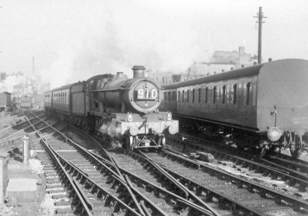
For long distance trains, the country is split up into areas based upon the old British Rail regions. Each one is assigned a letter as follow:
- E: Eastern
- L: Anglia
- M: Midland
- O: Southern
- S: Scotland
- V: Western
A train going from one region to another is given the letter of the destination region in its head code. Prior to 1967 N was used to signify trains destined for the erstwhile North Eastern region. For trains internal to a region, the remaining letters can be used to indicate either:
- A destination zone inside that region,
- A route within that region.
Some areas within the Midland region are:
- A: London
- D: North Wales
- G: Birmingham
- H: Manchester
Other regions can use these letters for different areas, but the inter-regional codes have the same meaning throughout the country.
In 2007, a special letter Q was introduced for track recording trains, such as the Network Rail New Measurement Train. This emphasises to signallers that the train is to run its booked route as it is recording, not to be diverted without the prior knowledge of the Controller. Prior to this, trains operated by British Rail Research Division used the letter T. The letters X and Z are generally reserved for special use like steam specials, shunting engines and other
Because there are many trains of the same type heading for similar destinations (for example, most expresses to Scotland have head codes beginning with 1S) the last two digits are used to separate individual services or to indicate the route (generally for suburban services).
There is sometimes duplication because there are only two digits, so for individually numbered trains that there must be six hours between services with the same head code.
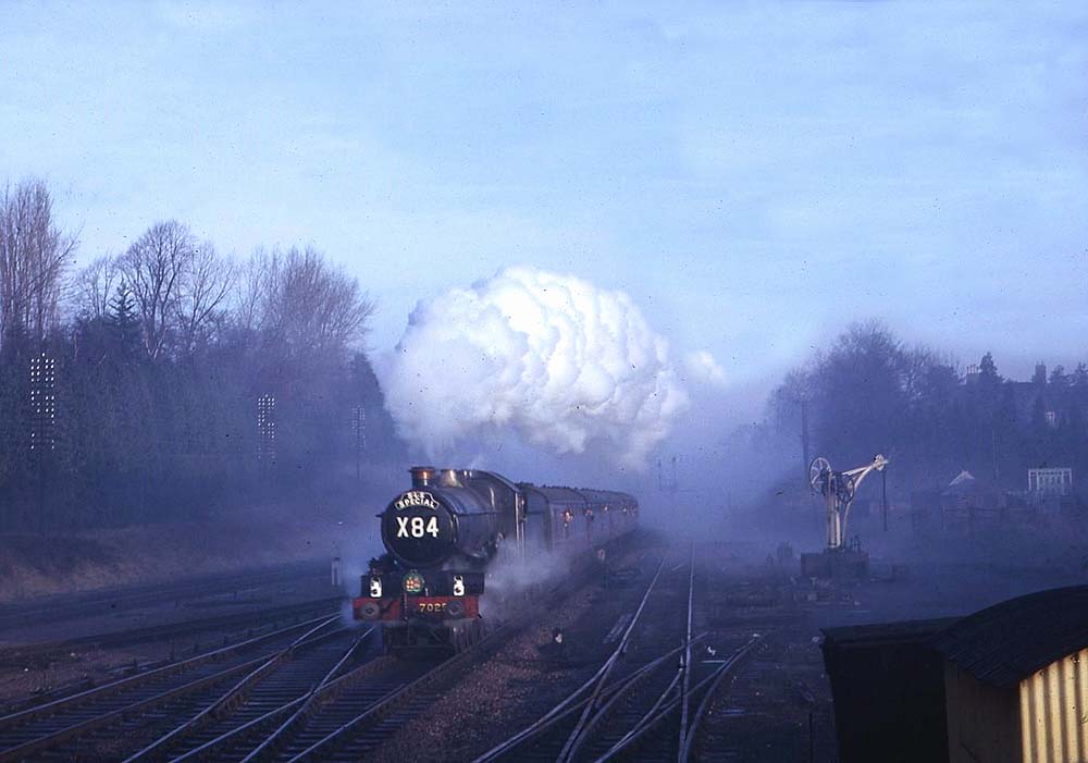
3.31 – The German signal system
The German signals are the most known signals. This signals are widely spread because of the majority of model trains Germany has produced. Famous and well know model train manufacturers like Märklin, Minitrix and Fleischmann has produced a vast amount of model trains including enhanced scenery that of course contains the German signal system Most model trains are based at the German railroad companies. KPEV, Kon.Bay.St.B, Kon.Pr.St.B, DRG, DR, DB and DBAG and in addition the German private companies.
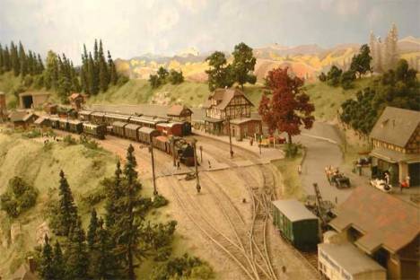
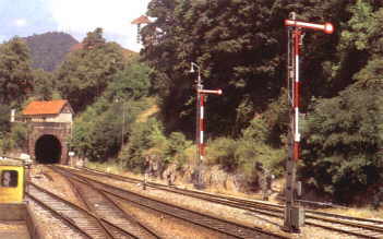
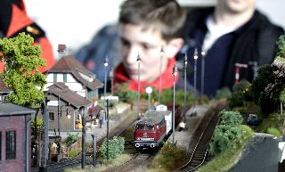
Model railroaders often has their theme based at the landscape of Germany during the steam era which demands actually the installing of the German signal system as well. The last two decades other countries are raising and the models are rapidly growing.
TS2015 provides a several lines that are straight from Germany. One of these lines is the Ruhr-Sieg line which has a fine scenically view. Since the coming of the RS Line. the number of available routes has increased and now the coming of the last route between Köln-Koblenz brought even one of the beautiful lines of Germany. Though the route is not finished.
To get the full understanding of the German signals you have to practice them. However the German signal system is quite simple to understand, but needs some attention in order to interpret the signals and anticipate in a proper way.
The Buchfahrplan” contains the speed limitation accordingly the kilometerpost along the route. Each kilometre/hectometre post is notified in the “buchfahrplan” and notifies every speed restriction that has to be achieved accordingly the kilometre post in the “Buchfahrplan”.
The German signal system partly depends on the “Buchfahrplan”. Every track and line got their own number and “rulebook” this rulebook is present in every engine driving the area of thier designation. Behind the driver there is a library with almost all available lines and routes in Germany. Each route and line is described with their own special occasions and situations.
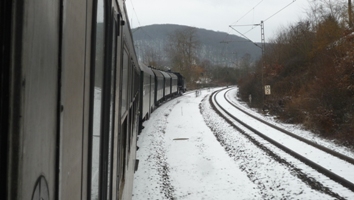
In modern days all these information is now stored on Hard Disks on the train computer and can be accessed by the main screen of the leading cab. In the past a card holder covered with glass did contain the track notifications and the “buchfahrplan” and either the brake sheets, orders and warrants if present.
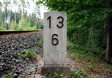

They are installed at every 200 yards spacing between the posts. The yellow markers above and underneath the kilometre post are in use at high speed lines and ordering the driver to overrule the emergency brake system when entering a tunnel.
The issue is that when an situation occurs in a tunnel almost no other services can reach the train when an emergency brake has been applied. The train needs to get out the tunnel in the first place to perform an evacuation.
If the Buchfahrplan mentioned 60 km/h at km. post 60.3 you are not allowed to exceed the speed restrictions at that point.
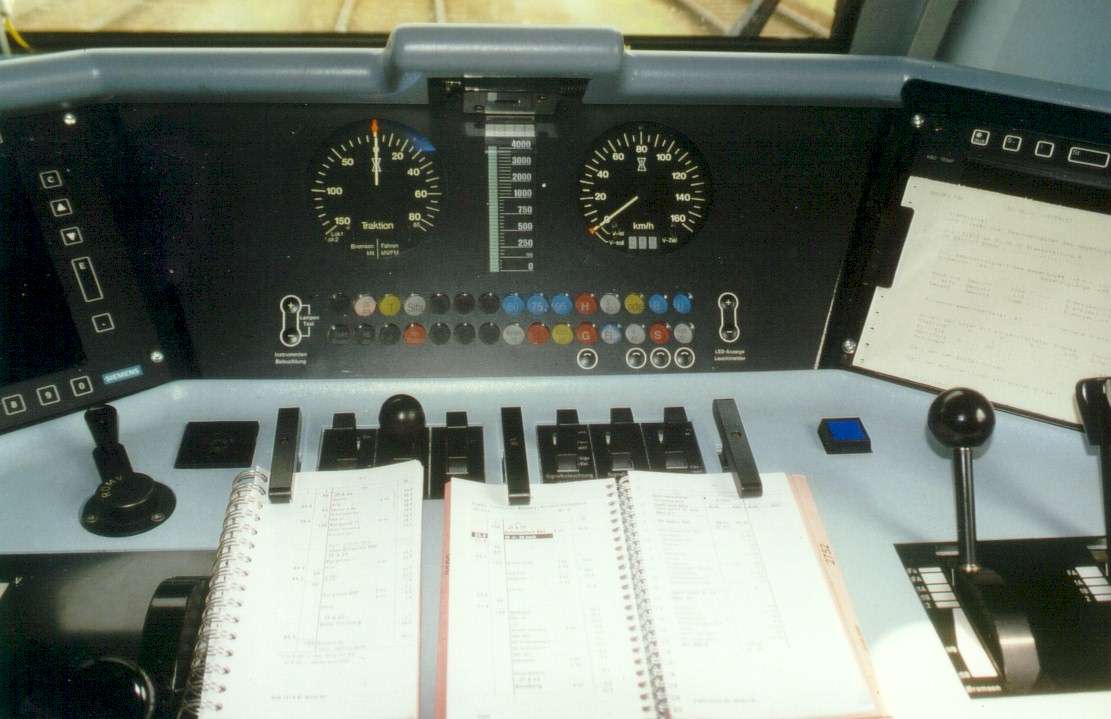
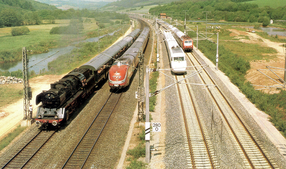
3.32 – German main and distance signal aspects
Signal markers are in use to show the state of the signal and to recognize the type of signal which will determine the action of the driver after notifying the markers. The coloured markers are installed at the signal post half way the pole.
____________________________________________________________________________
The signal is not to be passed at red unless a warrant is given or ordered by a communication method.

____________________________________________________________________________
The signal is allowed to pass if the signal remains in a danger aspect and when no communication is available. Proceed not to exceed 40 km/h while scouting the track.

____________________________________________________________________________
The signal shows a 3 aspect Ks signal and is combined with one of the markers above.

____________________________________________________________________________
Grade crossing protection. If remains red communicate with the CTC if no communication is possible act as a permissive signal. Stop before the grade crossing and secure the grade crossing to pass safely not exceeding 15 km/h. Then continue scouting the track until the next signal.

____________________________________________________________________________
Stop before the signal.
DBAG Signal book DV301; Hp 0;
.


The main signal here shows a danger aspects and tells the driver to stop before the signal.
There is no need to show the next aspect at the distance signal because the main signal here shows the danger aspects and the distance signal however shows a “Prepared to stop at the next signal” remains invalid. In order to avoid any confusion and probably clear aspects at the next main signal, the distance signal remain in the default “Prepared to stop at the next signal” aspects, until the line is cleared and the main signal changes aspects, the distance signal aspects changes with it. At the moment the main signal shows a “proceed” aspect the distance signal becomes valid no matter the aspects the distance signal shows at that moment.
The marker posts at ground lever just before the distance signal tells the driver what kind of distance signal this is. This signal marker is mentioned later in this chapter.
____________________________________________________________________________
Prepare to stop at the next main signal.
DBAG Signal book DV301; Vr0:


____________________________________________________________________________
Proceed with track speed.
DBAG Signal book DV301; Hp 1;

____________________________________________________________________________
Expect clear aspect at the next main signal.
DBAG Signal book DV301; Vr 1;

____________________________________________________________________________
Proceed not exceeding 40 km/h.
DBAG Signal book DV301; Hp 2;


____________________________________________________________________________
Reduce speed, not exceeding 40 km/h at next signal.
DBAG Signalbook DV301; Vr2;


____________________________________________________________________________
Ks Signals now taking over the older light and semaphore signals as they are in use at DB and DR (now all converted into DBAG) This signals shows the follow up sequence combined with “Zs” speed restrictions. This new signals are installed and operational on new build and upgraded lines. Every line that is undergoing an upgrade will have Ks signals installed as well.
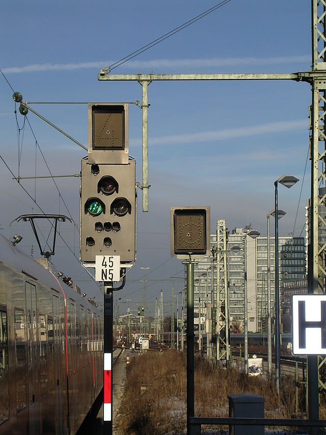
The new signals are based at the same design as the last redesigned Hp and Vr signals as they are installed and operational at the Köln-Frankfurt High Speed Line for example.
The numbers shows the speed which should be multiplied by ten. The yellow number indicated an approach speed that should be held and not exceeded at the next signal.
The yellow speed indicators are always installed at a distance signal underneath the signal
The white speed indicators shows the absolute speed that should not be exceeded and is installed on top of the main signal.
____________________________________________________________________________
The approach to a distance signal is markered with 3 white beacons either with a different amount of diagonal positioned black bars. The distance is set for each bar at 75 meter. The last beacon is situated 100 meter prior to the distance signal.

- 3 bars = 250 meter
- 2 bars = 175 meter
- 1 bar = 100 meter
____________________________________________________________________________
The Bavarian signal is a main signal with a different arm . The signal shows beside the regular aspects also a “Resting” aspect. (Ru = Ruhe = Resting)
When the arm points downwards and a bleu light is visable the track remains in a situation of “Rest” which determine the track does not contain active traffic or movements. The signal remains now only in museums and heritage lines.
3.33 – German shunting signals and point indicators.
The German Railroad uses a simple system of shunting signals. However the most shunting signals used in TS2015 as displayed here. Now as already notified the German Railroad became famous due to Model train manufacturers like “Märklin”, “Fleischmann”, “Minitrix” and others.
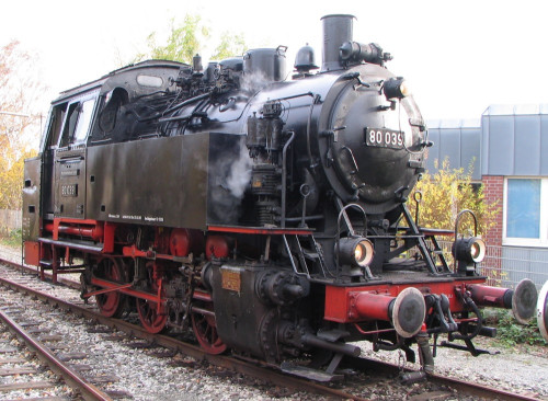
____________________________________________________________________________
Passing is prohibited
DBAG Signal book DV301; Sh 0;


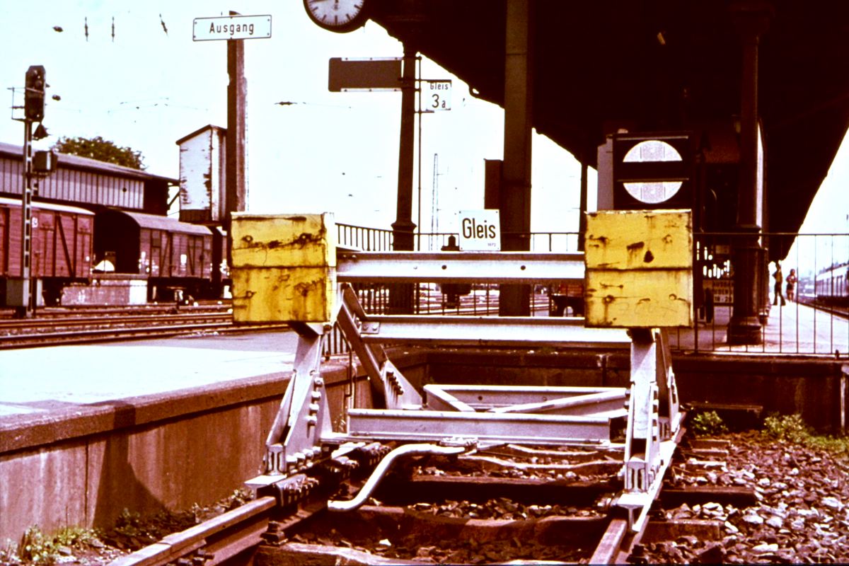
____________________________________________________________________________
Passing the signal is allowed
DBAG Signal book DV301; Sh 1;


____________________________________________________________________________
Shunting movements are prohibited to pass the marker.
“Halt fur rangierfahrten” means: Shunting limit!
DBAG Signalbook DV301; Ra 10:
____________________________________________________________________________
The spacing marker indicated the limit not to pass by trains that will eventually remain stationary at the track the marker is positioned.
Shunting movements are prohibited to pass this marker if the train will remain stationary at this track and the track directly next to the track on which the marker is placed in between both tracks. This is to remind the free spacing in between trains. Passing could cause a side collision and derailment.
DBAG Signal book DV301; Ra 11;
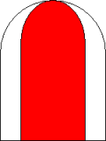

____________________________________________________________________________
Stop and wait before the signal
The signal is positioned aside tracks that does not have much shunting traffic. The clearance to proceed is given by a warrant or other communication device.
If the white lights are installed showing a light position signal is then equal to Sh 1 and passing is allowed when Sh 1 shown
DBAG Signal book DV301; Ra 11;
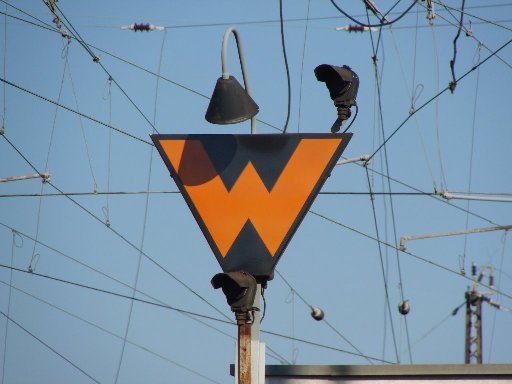
____________________________________________________________________________
Stop before the marker.
This marker often positioned at entrances, closed doorways, closed fences and closed tracks.
In some occasions the absolute stop marker is connected with a mechanic device connected to a fence, gate or door that will operate the absolute stop marker and will show a lunar white light.
DBAG Signal book DV301; Sh 2;


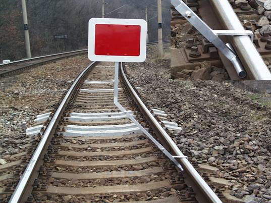

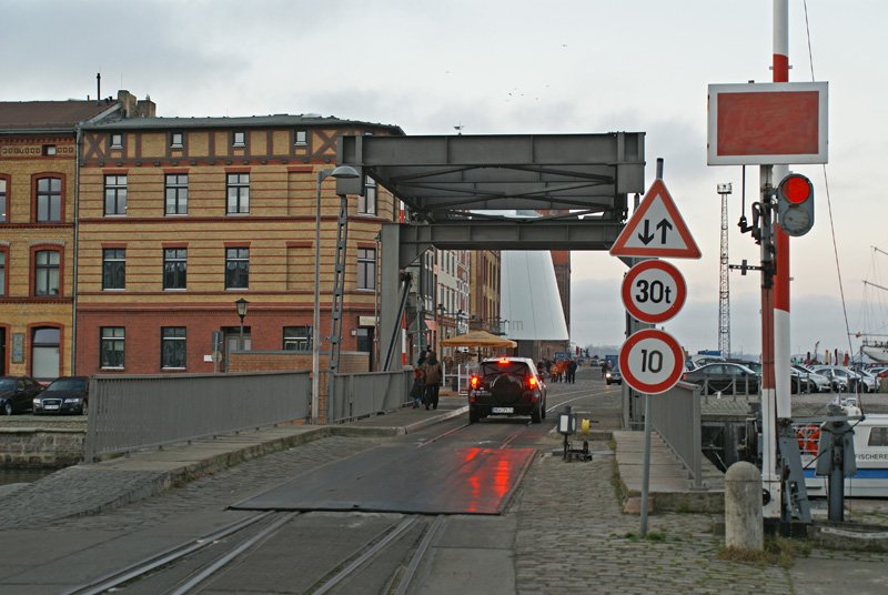
____________________________________________________________________________
The German Railroad company has always used point indicators. This is necessary due to snowfall. Points can be covered up by snow and the driver is unable to determine if the set route is indeed properly set well. The installation of point indicators at every point single-slip or double-slip is excecuted at every point within Germany, Austria and Switzerland. There are more countries using point indicators to give a better view and insight to the driver to determine if the proper route is set.
DBAG Signal book DV301; Wn 1;


DBAG Signalbook DV301; Wn 2;
The arrows indicates the diverted route either to the left or right.


DBAG Signal book DV301; Wn 3;
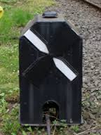
____________________________________________________________________________
Although in TS2015 these catch points ar inactive but it is possible they appear as static asset within a route or scenario. However the do not affect the scenario. In practice the catch points are to protect main line for run-away wagons. Run-away wagons will derail away from the main track to prevent severe accidents on the mainline. Though derailment could cause damage as well to the wagon and siding, but an accident with casualties will not appear.
DBAG Signal book DV301; Gsp 2;

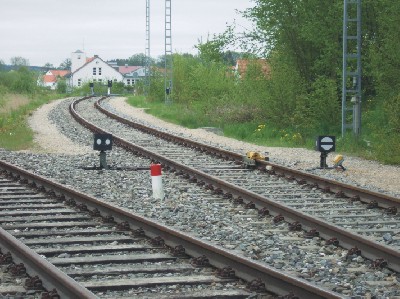
____________________________________________________________________________
3.34 – German permanent signal aspects
Distance and approach markers are installed just in front to the distance signal to indicate the type of distance signal.
- When a marker is not placed right next to the signal, the signal then is a repeater signal.
- When the marker is visible only, the marker then represent a distance signal: the driver now must get prepared to stop at the oncoming main signal. This is mostly the case on branch and local lines with a sparse amount of running trains.

- Distance signal marker: 2 aspects
- Distance signal marker: shortened brake distance to the main signal.
- Distance signal marker: 3 aspects
- Distance signal marker: 2 aspects used at DR lines with PZB magnet.
The use of distance markers only is mainly used at lines with low frequency of traffic.
____________________________________________________________________________
Ne Markers and posts overview chart
The use of distance markers without distance signals is in use at lines without a lot of rail traffic, mostly operational at local lines and branch lines. To regulate local lines and branch lines with low rail traffic a simplified signal system is in use.
The Letters “Ne” represents the phrase “Nebenbahn” (Local track or Branch line)
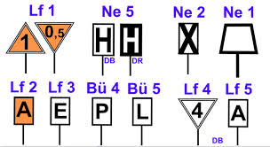
____________________________________________________________________________
Proceed prepared to stop at the oncoming “H” post.
DBAG Signalbook DV301; Ne 1;


____________________________________________________________________________
Stop before the “H” marker.
(The “H” represents the word “Halt”)
The “H” marker is similar to departure signals and covers (spring)points. The marker is to be passed after permission of the local station chief, signal box in charge of the line or other authorized crew responsible for that line. The authorisation can be given by phone, radio or a warrant (Befehl)
The signal is also in use at platforms, an additional marker contains text like “Kurzzug” (short train), “Vollzug (Medium train) and “Langzug” (Large train) and determine the place to stop according a certain amound of coaches the trains has.
DBAG Signal book DV301; Ne 5;
____________________________________________________________________________
Proceed and if scheduled prepare to stop at the station within braking distance.
DBAG Signal book DV301; Ne 6;
____________________________________________________________________________
Whistle for at least 3 seconds.
DBAG Signal book DV301; Bü 4;
- The regular post: aspect: Whistle for at least 3 seconds
- The regular post inversed with the same aspect as above
- A double “P” whistle post: aspect: whistle two time in sequence each whistle at least 3 seconds.
- The additional white plate with two black bars indicates to whistle if not stopped at a unprotected grade crossing.
The “P” represents the word “Pfeifen” (Blowing the horn)
____________________________________________________________________________
Ring the bell when passing a grade crossing remain ringing until the whole train has cleared the grade crossing
DBAG Signal book DV301; BÜ 5;

The “L” represents the word “Lauten” (ringing)
____________________________________________________________________________
Proceed prepared to stop at the next “H” signal post.
DBAG Signal book DV301; Lf 4;

____________________________________________________________________________
Proceed, not exceeding posted track speed.
The number represents the speed in kilometres per hour multiplied by 10
DBAG Signal book DV301; Lf 7;
____________________________________________________________________________
Proceed prepared to stop at the next “H” signal post.
DBAG Signal book DV301; Lf 4 DR;
Speed posts DR style does mention:
- The track speed if the post is positioned at a signal or at the start of a local, main or branch line.
- Approach Speed announcement posts that announced a restrictive speed when posted at a line or point where higher speed is the track speed, then proceed prepared to operate at posted speed (Lf 5) through permanent speed restriction.
The track speed is given in Kilometres per hour.
____________________________________________________________________________
Proceed at speed posted on the Approach Speed Limit Sign.
DBAG Signalbook DV301; Lf 5 DR;

____________________________________________________________________________
Proceed slow down not exceeding posted speed at next zone start post.
The number represents the speed restriction given in Kilometres per hour multiplied by 10.
DBAG Signal book DV301; Ne 1;
____________________________________________________________________________
Proceed with caution not exceeding posted speed.
The “A” Represents the word “Anfang” (start)
DBAG Signal book DV301; Lf 2;

____________________________________________________________________________
Proceed not exceeding normal track speed when the entire t rain has cleared the “End” marker
DBAG Signal book DV301; Lf 3;

____________________________________________________________________________
Trains diverted out of a restricted speed zone and passing the cancelation marker are allowed to proceed at track speed unless the entire train has cleared the cancelation marker.
DBAG Signal book DV301; Zs 10;

____________________________________________________________________________
4.00 – Additional driving experiences
Study the next chapters is therefore necessary to have the full understanding of the different driving skills.
4.01 – Driving up and down sloped tracks
401 Driving up and down sloped tracks
Now before you set of, climbing or descending a sloped track, you need to mention a several important issues concerning the boiler and brakes. It is therefore important to know the track and landmarks in order to anticipate on the oncoming things to take care of.
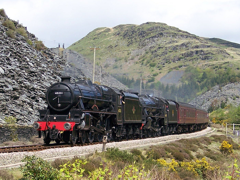
When the slope begins, act like you do on acceleration.
Do not inject water during a climb unless it is highly necessary at low water!
If necessary stoke continuously not exceeding 85% coal rate in the firebox.
When you are not sure about the pressure and water level prior to the climb you better stop at quite a distance (3 miles / 5 km.) from the slope and build up the water level and/or steam pressure. Then you have enough levelled track to gain speed to overcome the slope(s).
Try to find the right balance between driving and building up pressure. That’s why it is necessary to avoid injecting and feeding the boiler. The water level could drop tremendously. Keep your speeds steady during the climb trying to create and build up stem pressure.
Once at the end of the slope, inject water immediately.
Take a closer look at the next sketch showing you the water level on horizontal position in the boiler.
Underneath you see the boiler position when the engine is climbing. All water comes towards the cab and it seems you have the water level correct.

Watch a Black 5 climbing the slope.
Once om top of the slope, start inject water immediately in order to avoid to dry out the top of the firebox. Reduce the reverser and continue the run as mentioned.

Apply your brakes smoothly and adjust the brake pressure in order to keep up speed NOT exceeding the local speed restrictions.
During the run down the slope, set the reverser a 5% and reduce the regulator at about 10%. This action causes the engine to roll down the slope. This is called “Coasting” and can also be managed at levelled track in order to slow down on approach of a certain point, yard or station. Now after a while of “Coasting” open the cylinder draining pipes to drain off the water. You now can feed the boiler. Increase the blower rate because during a free run you can stir up the boiler pressure again prior to pick up the run and in order to keep up the pressure to inject the water.
Now when you have to pick up the run increase the value on the reverser, then release the brakes you have applied. The engine will pick up the progress working on the run smoothly. Increase the regulator up to 75% and regain to drive at exhaust leaving the regulator in the same position.
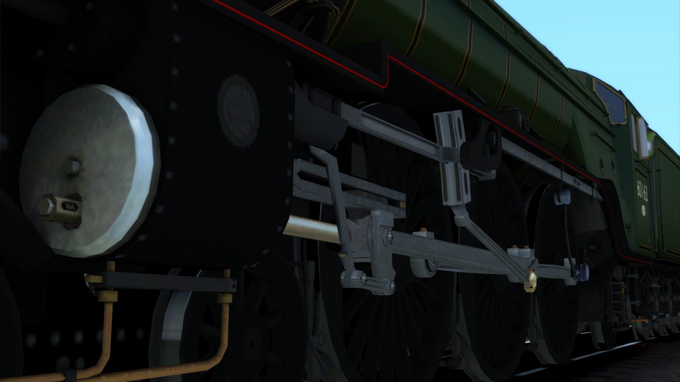
4.02 – Driving tender first
Driving tender first instead of head first requires a different approach of driving skills.
First of all the point of view is actually behind the drivers view. When driving backwards the point of view is constantly behind while the operating instruments does not change to the tenders side.
In comparison with a diesel or electric, the cabin usually has two operation panels either in both direction and often on a second cabin which fails a steam locomotive.
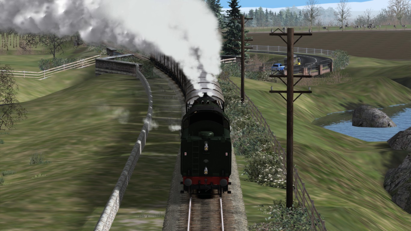
This means in reality at a steam locomotive, you have to turn around every time you drive the engine in order to get a full view. The regulator, reverser and brakes are at your other hand and you must regularly aim your view at the gauges to get the adequate information to anticipate on.
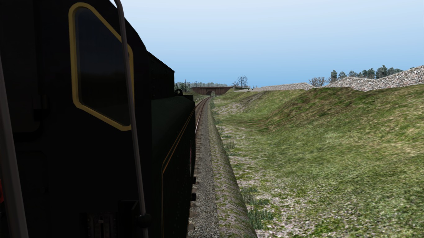
Driving tender first requires an extra attention and vigilance though in the real situation the fireman is the 2nd pair of eyes at the other side. The interaction between you and the 2nd man is therefore tremendously important and you have to rely and trust each other completely to get the best information and even beyond the necessary information than needed.
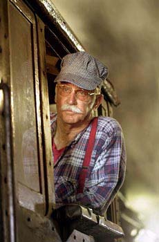
In TS2015 you have to switch your POV regularly to get the best view available on the right moments. You have to get common with the keys you need to switch fast using the
keystrokes:
- [ 1 ] Cabview
- [ 2 ] POV outside the train at the front
- [ 3 ] POV outside the train at the rear
- [ 4 ] POV trackside photographers position and spot.
- [ 5 ] Passengers view
(the arrow keys will change the coach if applicable) - [ 6 ] Top down view
- [ Shift ] – [ 2 ] Leaning out of the window
(starts at drivers POV)

Depending the chosen POV in or around the players train keystrokes listed above you can use the arrow keys to change the POV with:
- [ left Arrow ] (turns towards) the POV at the left side.
- [ Right Arrow ] (turns towards) the POV at the right side.
- [ Arrow Up ] (turns towards) the POV at head first.
- [ Arrow Down ] (turns towards) the POV at tender first.
The best tool to operate the POV is the use of the mouse. By operating the mouse you can adjust the POV accurately in a simple action. An advanced mouse can be added to the simulation with extra programmable buttons which gives more freedom of playing.

The POV can be expanded by splitting the view divided over three or more monitors as well.

An excellent configuration of 5 monitors in the vertical position that widens the vision abundandtly.

The view of tender first driving is for common people not ecstatic. They always got the wrong impression a steam locomotive could only run forwards.
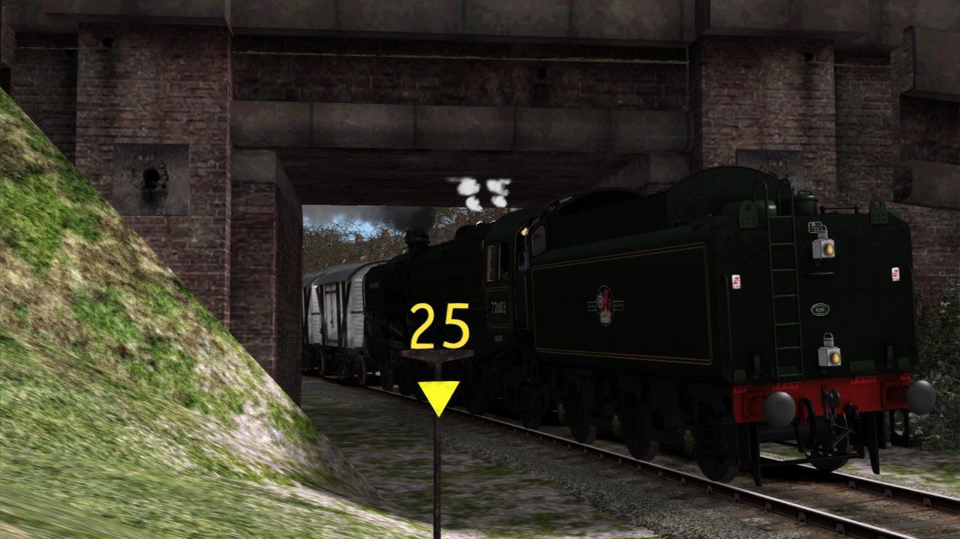
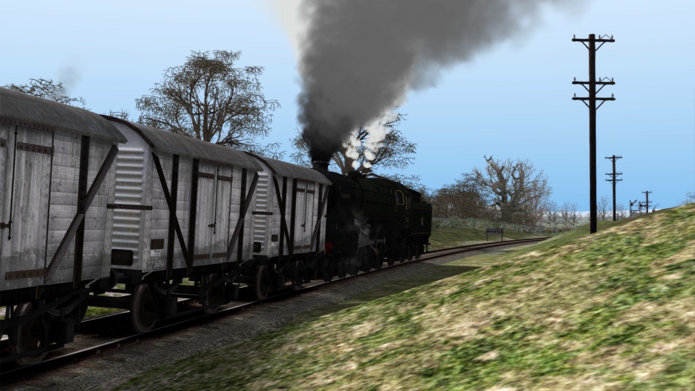

Driving tender first means to have the tender in front of the engine. However the engine is driving backwards the tender is still with the engine in the driving direction. The tender carries all supplies needed for the run. The tender is equipped with a rigid coupler bar that is connected to the tender and either locomotive by a coupler pin.
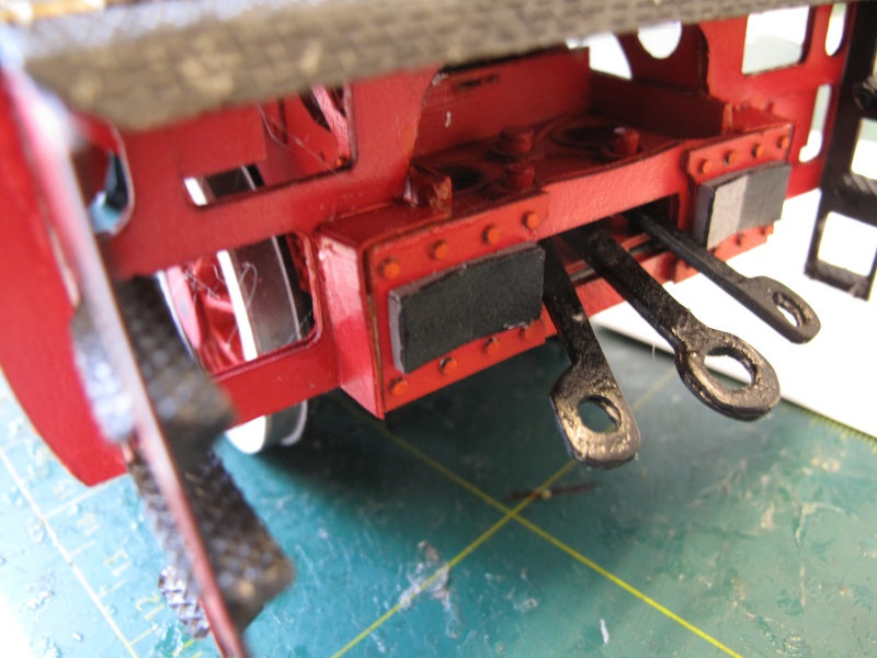
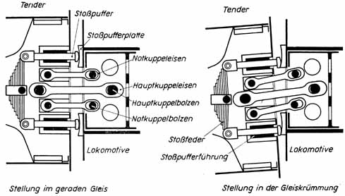
(in German language) shows the overview and positioning of the tender coupler between locomotive and tender.
This system at the diagram is German based and could be found on every German manufactured engine on the European mainland. Other manufacturers has different coupler systems which was mainly a rigid coupler bar is fitted between engine and tender. The working of the rigid coupler bar and the secondary coupler bars are clearly visible. The spring buffers shows the state when the engine goes straight out and when moving in a curve.
The tender axles are quite close near the engine. the configuration of these axles is aimed to optimize and balancing the total weight including the mass of the water and coal.
However when the tender heads first on a run, the engine absorbs the mass of the tender at the buffer plates causing more violent vibration in the frame of the engine because of the unbalanced tender carries out to the engine when a certain speed is reached.
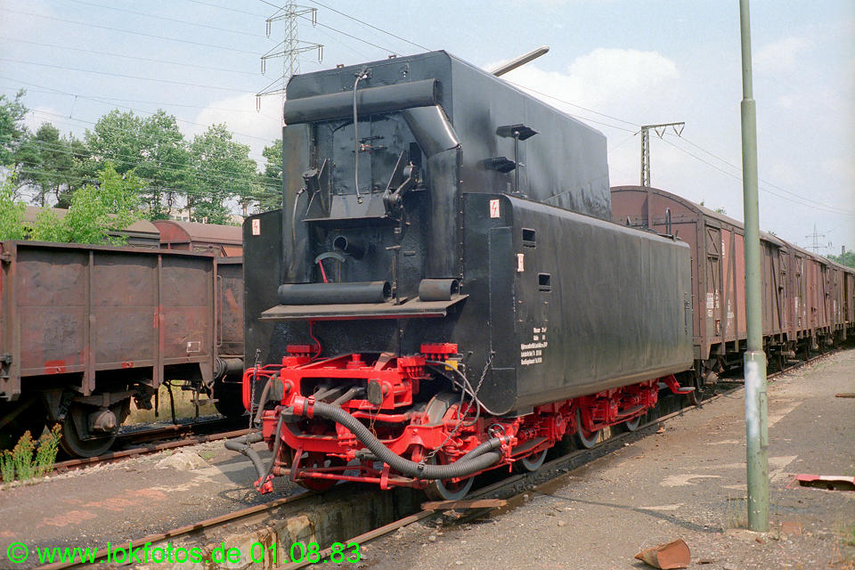
The side coupler bars is to prevent a runaway train when the main coupler bar should break and secondly the side coupler bars also maintain the stability of the tender. The buffer plates next to the coupler bars are placed to hold a pyramid shaped buffer which is fitted at the engine.
When driving backwards the tender does not interact with the engine itself. The pilot truck guides the frame of a steam locomotive into curves and pulls the engine into that curve. The tender does not function like a pilot truck and does not pull the engine into a curve. The lateral forces due to the centrifugal motion curves does pull the engine sideways and the running force is boosting the lateral centrifugal forces after all which will cause the engine to derail much earlier.
Mentioning both issues, a speed limitation on a tender first service is a safety regulation to avoid any derailment.
A derailment of a tender could cause severe damage to tender engine and in the worst case the whole train.

4.03 – Shunting and branch line operations
Plantations and industrial area’s are depending in a large scale on the railroad. Many supplies to fabricate product are brought in by rail. Shunting is therefore needed to have the industry working. Wagons from all sorts of industry has to be managed, preordained and set out to other tracks at the yard combining new freight trains at the shunt yard.
To shunt, apply the engine brakes slightly to avoid overspeed. If applicable use the bell when approaching a level crossing by pressing [ B ] use the regulator smoothly and do not extend the reverser for more than 25% unless the start force requires more to put the train in motion. Set the headlight accordingly the country restricted head light codes.

Mass of freight are passing the yard every day. Also chemicals are passing the freight yards to get to their destination.
Tanker wagons can contain all sorts of liquids. liquids that comes from the oil plant are highly dangerous to handle. the content of tanker wagons is mostly deathly for humans. liquids from different chemicals react very differently with oxygen and/or water. Some chemical liquids will explode when it comes in contact with water. other will evaporate when colliding with air forming a toxic gas or liquid you better do not touch or inhale.
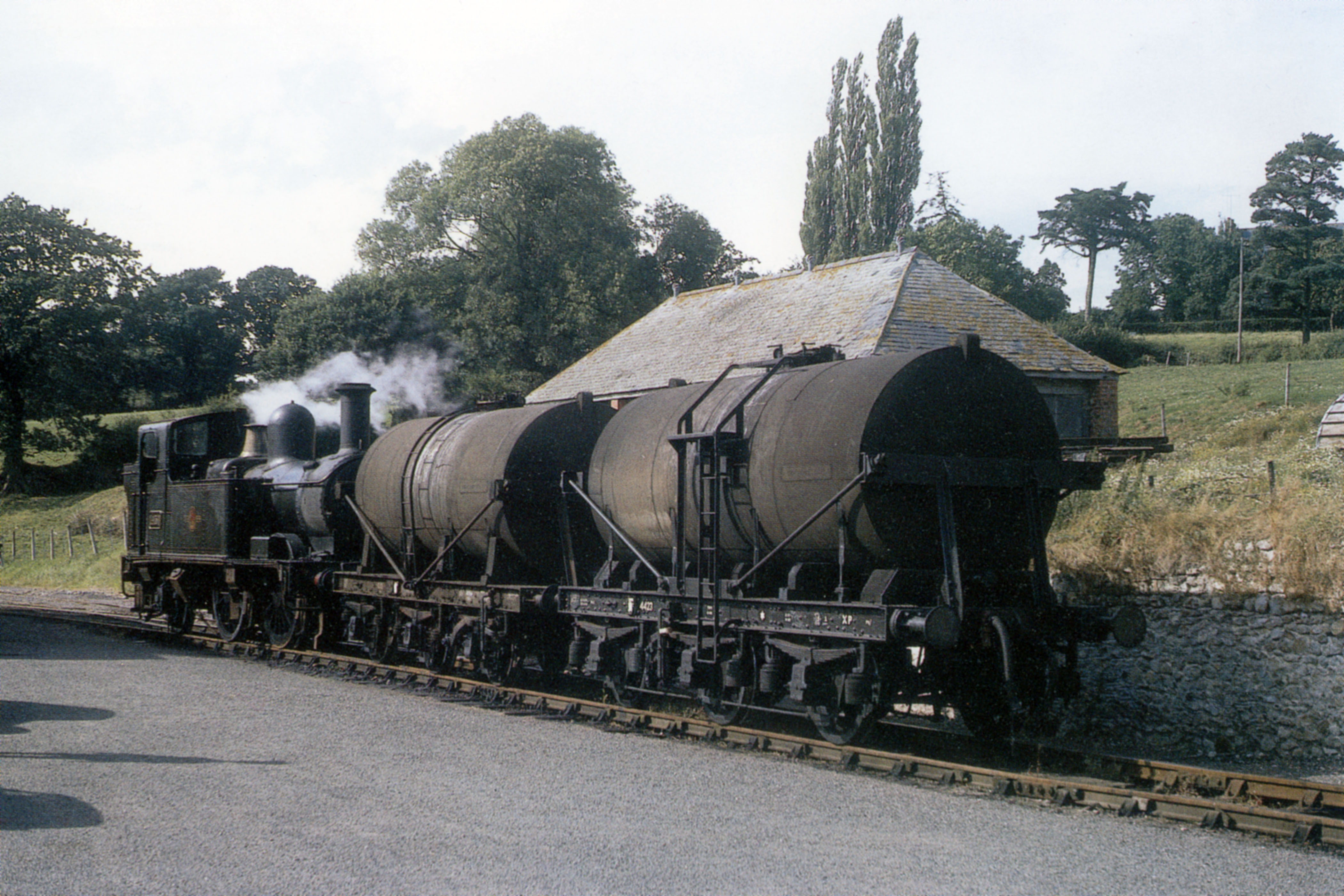
The way you shunt a tanker wagon with mineral oil or liquids always require special attention. Most chemicals may not get over the hump, but needs to be sort out separately.
In the days of steam driving at oil plants brings the risk of explosions caused by the fire of the steam locomotive. Engineers came up with a solution to create the fireless steam locomotive. A fireless steam locomotive contains a boiler without tubes and pipes. Ste fireless steam locomotive was subject to a stationary boiler which most mostly stored in a power house at the oil plant.
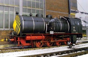
At some plantations today the fireless steam locomotive is still in use in area’s with a high risk of explosion. Diesel engines sometimes blow out a torch flames, causing by a defect or malfunctioning turbo that could ignite highly flammable gasses in the air at the oil plant.
A fireless steam locomotive does not have a torch blow out, neither any fire in a fire box.
Even pressure is a much more safe issue. The stationary boiler provides the fireless steam locomotive of fresh steam. In the past old steam locomotives were in use at large scale after scrapping at the railroad company but many boilers were still certified for steam producing. Many steam locomotives were sold to different plantations and some are stil in use today.
Steam is produced in highly sophisticated and isolated stationary steam boilers mostly situated in power houses or boiler houses.
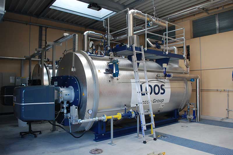
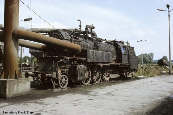
Steam from stationary boilers is transported by pipes throughout the whole plantation.
The fireless steam locomotive hangs on to it at about each hour after continuous operation.
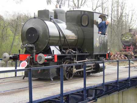
A special hose suited for high steam pressure is connected between the steam locomotive and the fireless using the steam heating as steam source. When both engines are connected, the driver or fireman at the steam locomotive opens the steam heat valve and the fireless starts to fill up. After 15-20 minutes the fireless engine is at the right pressure and the engine is operational for the next shift.
The steam pressure inside the fireless engine is about 180 PSI / 12 bar. the boiling point of water is at about 170 degress. The water produces steam by the high pressure.
The decrease of steam pressure causes the water to evaporate. The evaporation however creates steam and keeps the steam at pressure. The steam pressure does not decrease rapidly due to new produced steam by the water temperature itself. The balance between steam and water is maintained but the production of steam is subject to the usage of steam.
Because the heat source is not present the temperature slowly decrease and finally ceases the steam production. Before the steam production ceases, the engine needs to be back at the boiler or power house to refill / top up water and steam. Then the whole procedure starts over again.
Living cattle in a wagon are transported to abattoirs for further production of meet and other products. During transportation cattle need to have some space to move. A common cow weights about 900-1000 Lbs. / 450-550 Kg. To have cattle into the train special platforms called loading docks are created to load the cattle into the train.
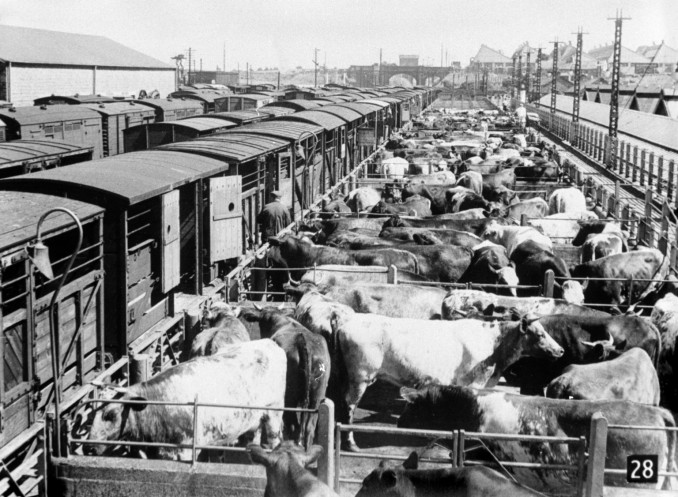
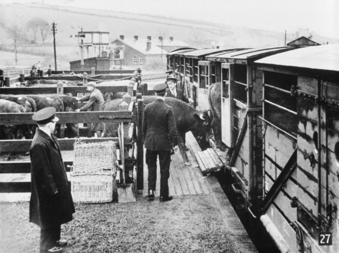

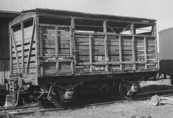
The cattle at the loading dock, a kind of work which need a lot of patience
During shunting it is important to shunt smoothly. When a cow should fall between other cattle will result in the impossibility the cow to raise up because the cow is surrounded by other cows. This could even kill the cow as well when the multitude of cows quelling and crushing the fallen cow. The wagon could derail because of certain changes in mass weight into a certain direction due to the unbalanced wagon.
Moving a train at branch lines has other difficult issues you have to deal with. A branch line does have a simplified signalling system. The speed is restricted to low speed approx. about 5-15 Mph. / 10-25 Km/h. depending the local restrictions.
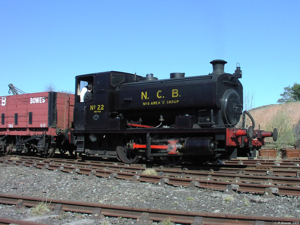
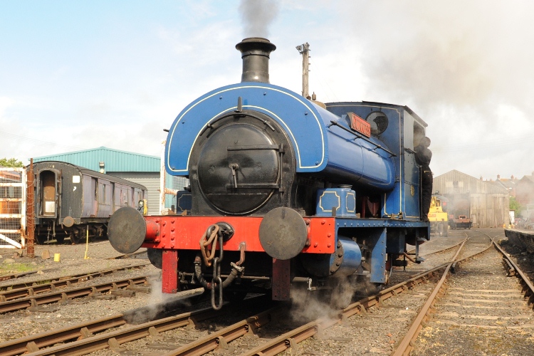
Moving and shunting such a lines requires scouting at the same time. Level crossings are often unprotected. A railroad worker is required to flag the traffic and signalling the driver to move on steady.

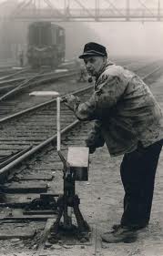

4.04 – Double headers and banking engines
Double heading driving is a major effort to add extra power to a train. This power is then needed to overcome the adhesive power t heavy trainsTS2015 does not always support driving using double headers. In comparison with MSTS driving with double headers was always possible regardless the engine or differences in traction. The differences between type of traction causes sometimes a problem when a steam locomotive leads.
A double header Black 5 at a steam special
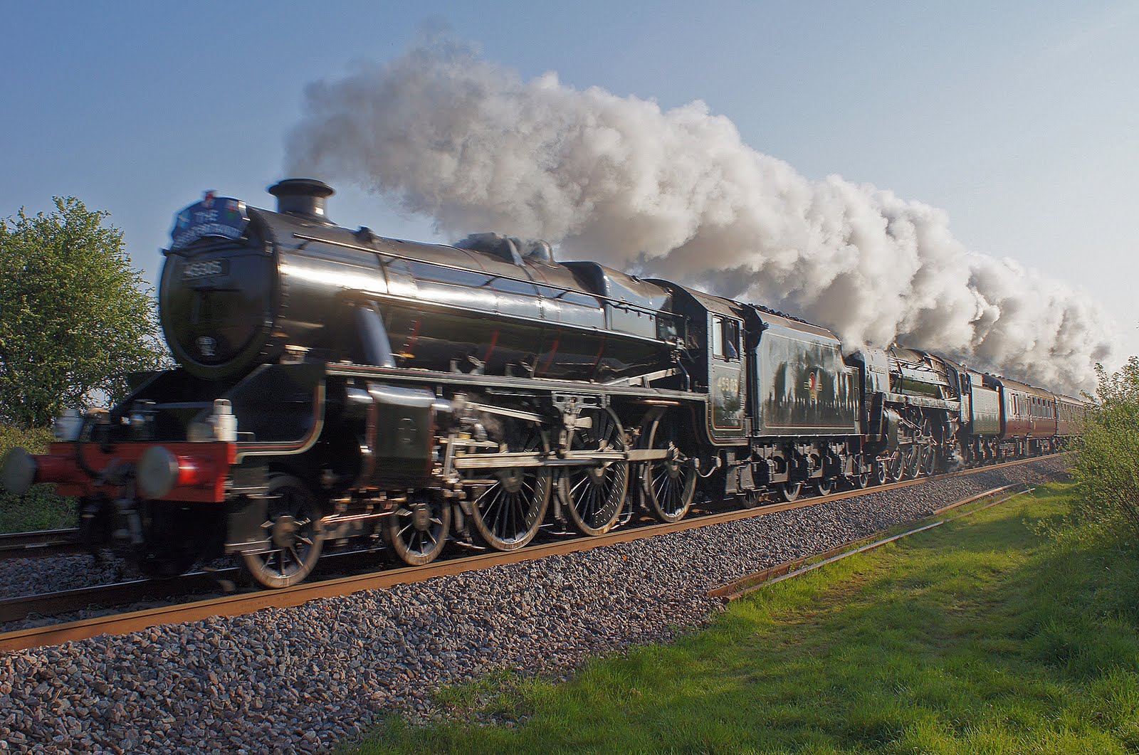
Some combinations are possible to do but difficult to handle. An example is a leading German class 03 and a German class E18. The problem is mainly the reverser. Because when the regulator is operated the throttle is operated as well. The steam reverser is in use to adjust the cut-off, but a electric or diesel does not have a cut-off system, it just switch forwards or backwards. There is no in-between scaling. This issue causes the main problem in the firt place. However MSTS was able to deal with this differences, TS2015 does not, unless the creators of steam engines has program the engines to make it possible to drive double headed.
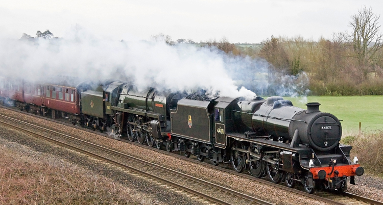
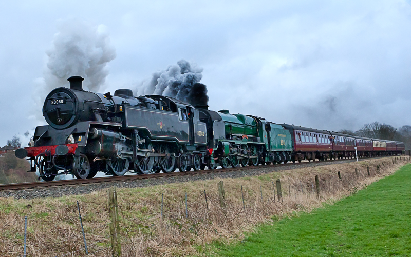
Double headers are possible at:
- Just Trains 4MT
- Just Trains 6MT
- Port Road Black 5 in AI traffic only
Do not use two double headers form different manufacturers like the Black 5 form the Port Road and a 6MT from Just Trains. However this is not reealy tested yet, but the LUA scripting for every enine is quite different. In the worst case TS2015 could crash.
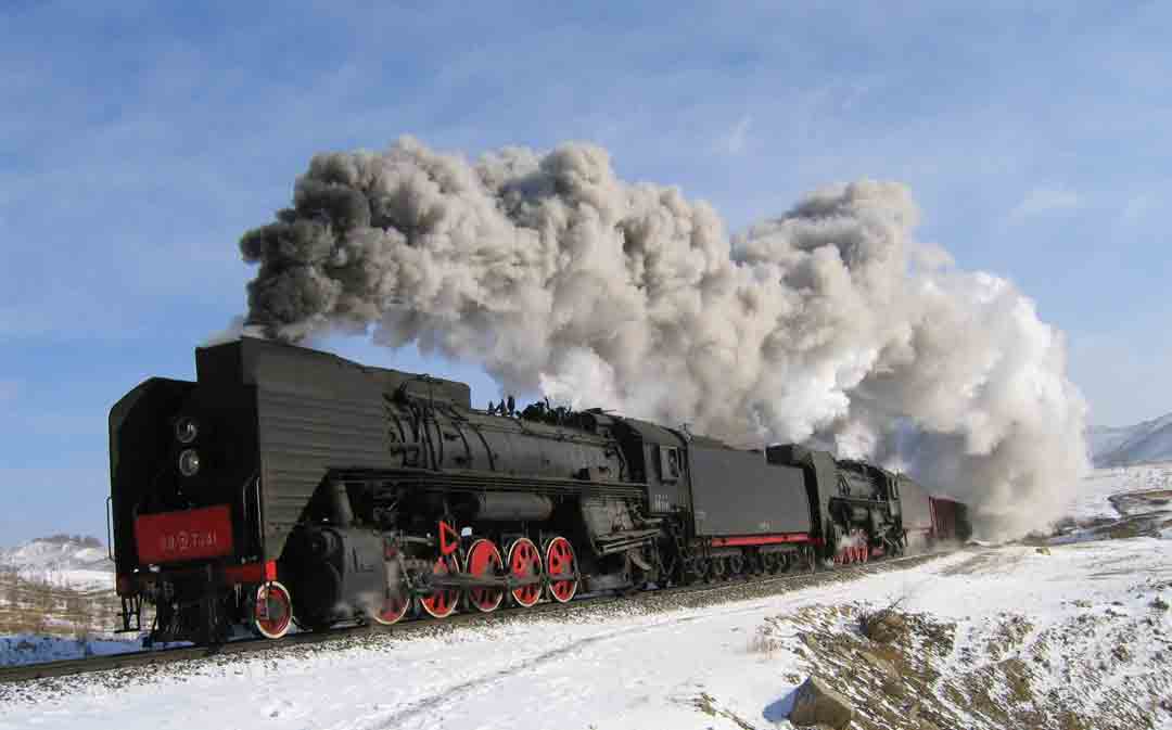
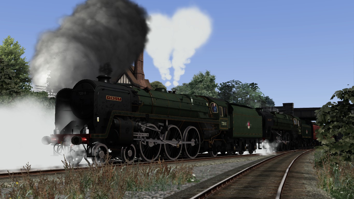
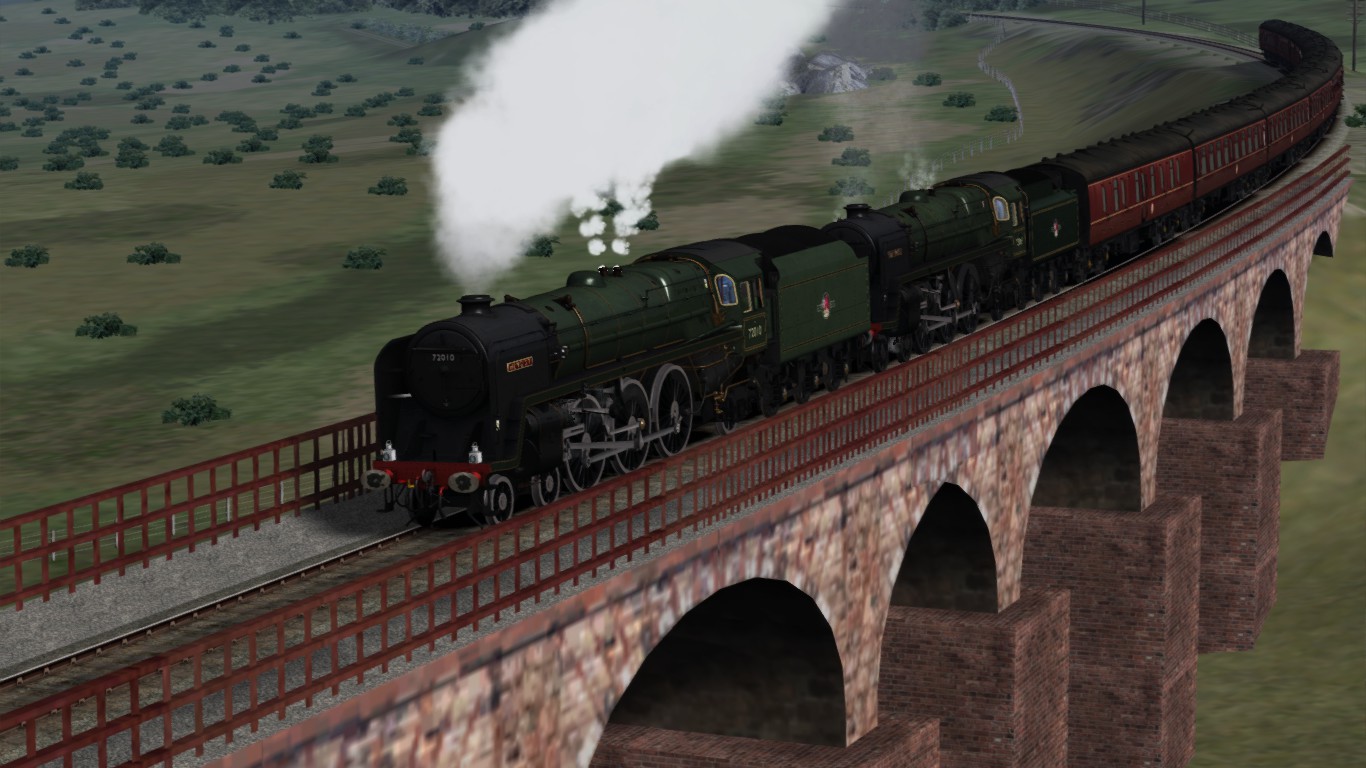
Another issue handling special driving is banking. A banking engine is a temporarily engine that push a train over a graded track without hooking on at the rear of the train. When the banking engine comes on top of the slope, the driver hold the banking engine and the train continue without stopping. The banking engine goes as solo engine back to the valley station and waits for the next banking order.
German Railroads Nr 3. “The Werrathal route” for MSTS contains a scenario (activity 20b) with a banking class Br 44 (2-10-0) at the rear of a heavy train loaded with sodium. You are the driver and have haul this 1200 ton sodium train. As known so far, banking is not possible within TS2015. This brings the old MSTS in advantage.
Doubleheaders with 2 x class (Br)44 and a class (Br)44 as banking engine at the Werreatalbahn from German-Railraods. MSTS double headers and banking engines can be operated from the players engine This feature is not available within TS2015 which is a great lack.
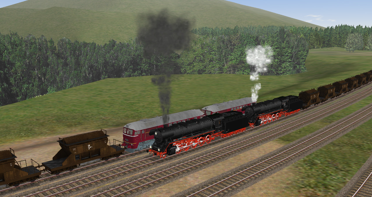

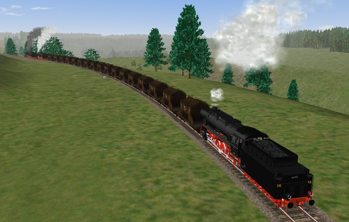
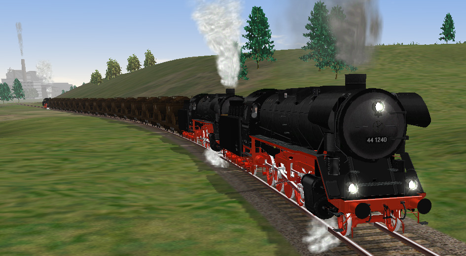
If you want to drive double headed heavy freight trains with a banking engine, you stil have to rely at the old MSTS until so far. You stil can feel the “Thrill” as far as possible within the limitations of MSTS.
A Pacific 01 118 with an unknown banking engine on its way at the Schiefe Ebene

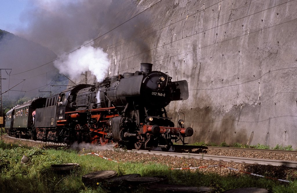
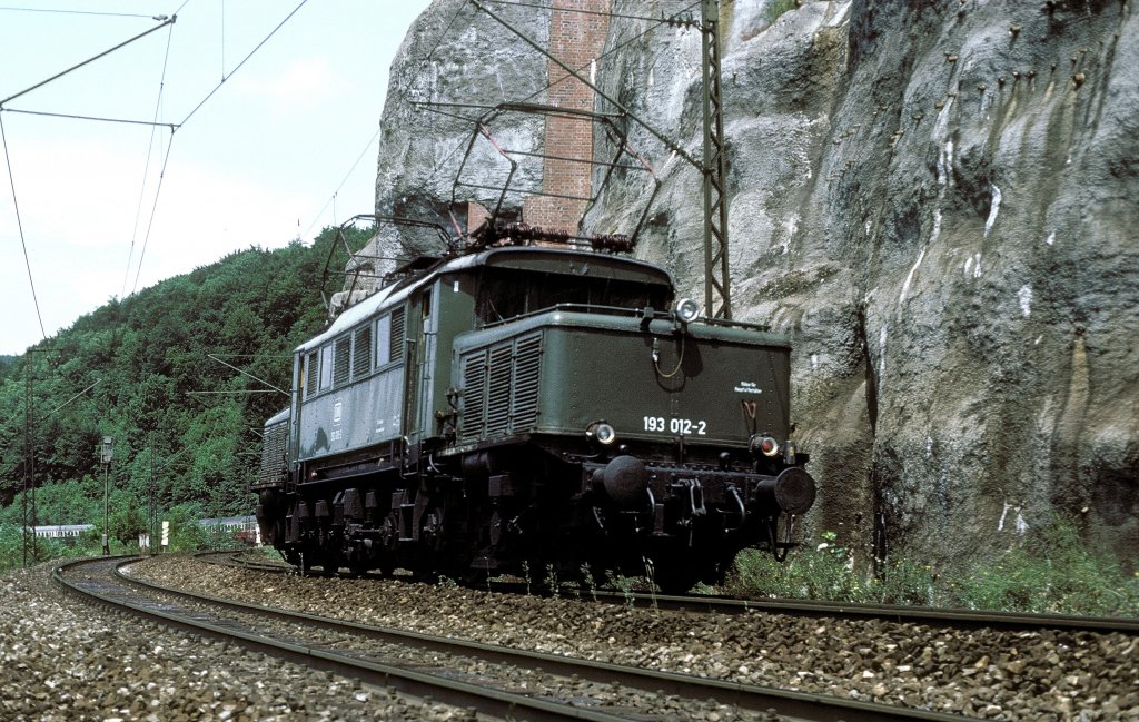
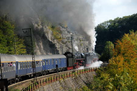
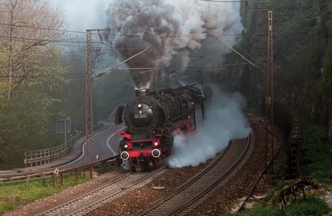
The Geislibge Steige is electrified. The class E94 did banking services here. After the job the engine went back to the valley station for the next banking order. The E94 is also available for TS2015. Together with the DMU VT08 in one package from Romantic Railroads will fit perfectly the steam era, enhanced with German freight in the 70’s and class E18
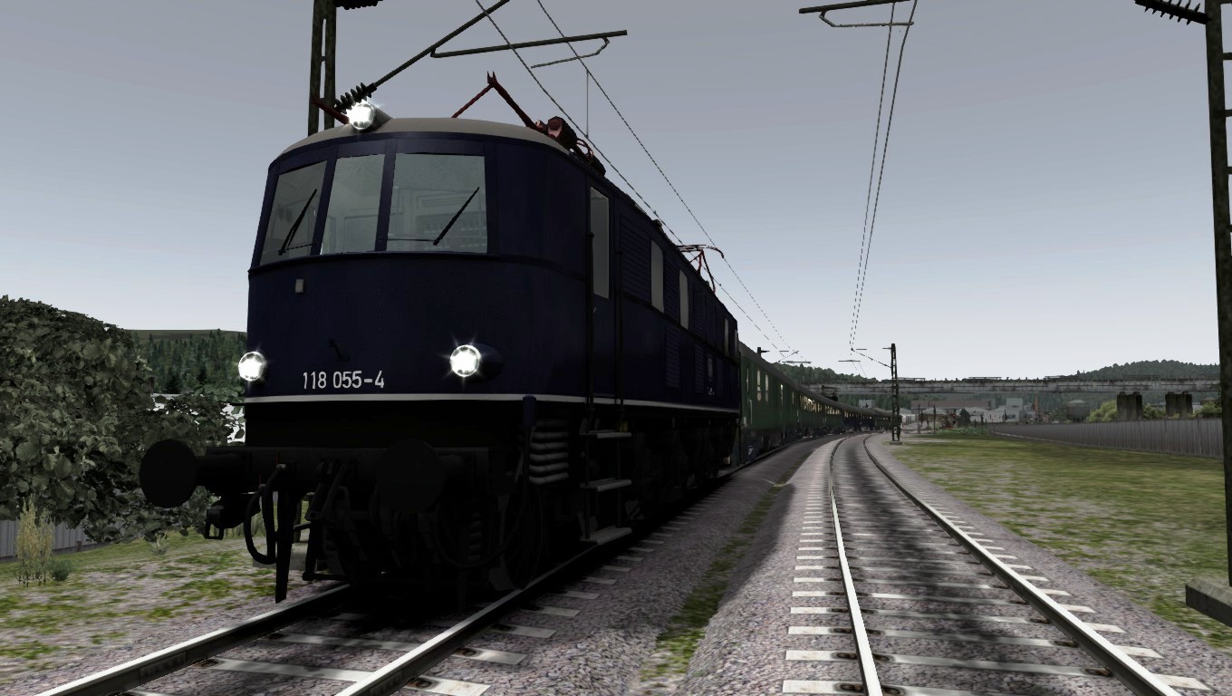
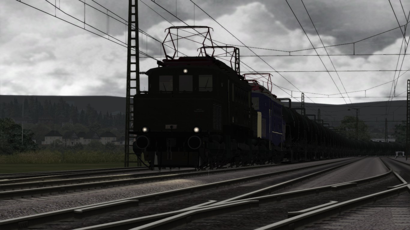
One of the most steepest graded tracks in Britain is the Lickey incline.
However the S&C just a few miles after Appleby starts a steep, but a lesser gradient with a long climb to the Ribblehead viaduct. A double header or banking engine would be needed to push up the heavy freight trains.
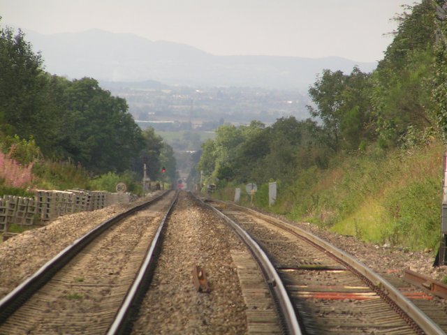
The Lickey Incline is famous because of that steep track. To get a good understanding how to operate the Llickey Inlcine, you take the position of a signalman. At www.simsig.co.uk you can download an operational signal table track diagram at SimSIg[www.simsig.co.uk]. There are some SimSig scenario’s included concerning the banking method at Bromsgrove.
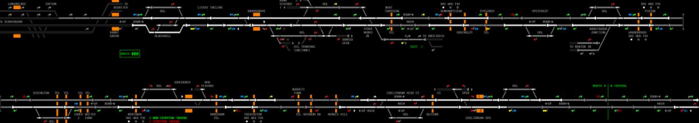
Some of the banking engines for service at the Lickey Incline

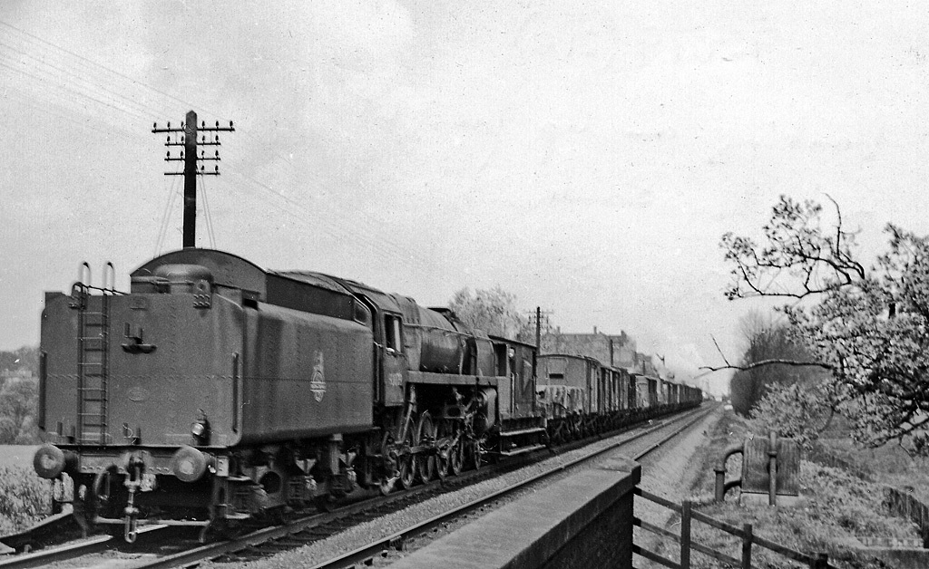

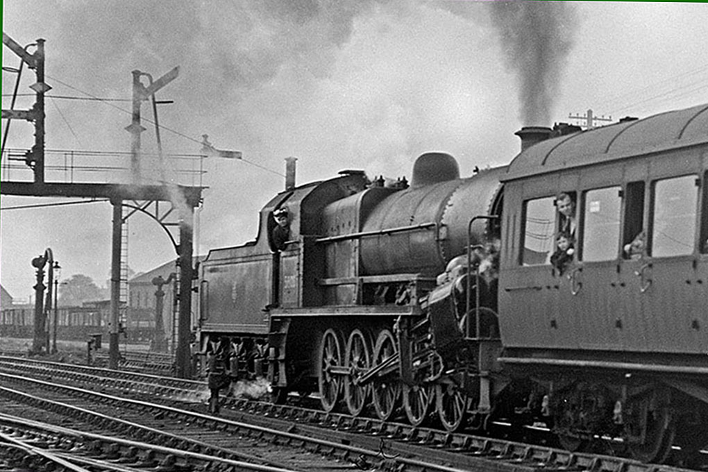

4.11 – Driving in weather conditions – Sea, storm, mist and fog
411 Driving in weather conditions – Sea, storm, mist and fog
Advanced weather is included in TS2015. even in 3D advanced weather is available. Snow, ice, blizzards, hurricanes, thunderstorms, heat, fog, it is all part of nature’s fury. The most of the weather conditions are simulated as well. After all we are dealing every day with the weather which interferes with our daily life.
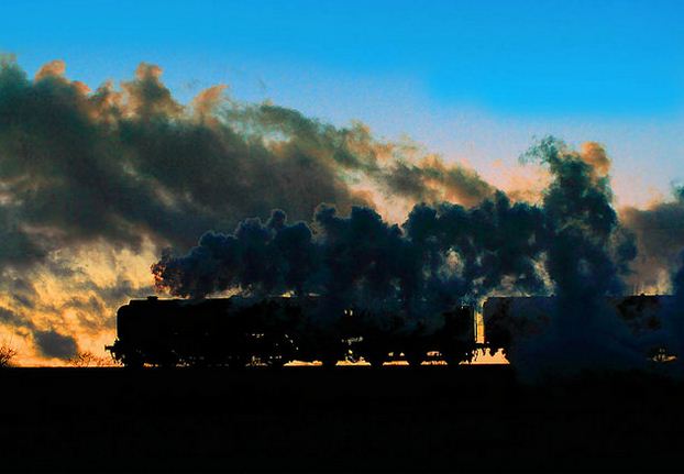
One of the best simulated weather storms is fitted in a scenario at the Sherman hill. A large freight train departs Laramie towards Cheyenne with the sun bright at the sky. The route goes across the new track westbound and once in the mountains, the sky has been covered up with clouds. It will get darker and darker eventually the sky turned black. Raindrops already starts to fall and not long after the first raindrop a hugh thunderstorm occurs.
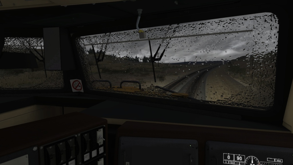

From the cab of a Dash 9, a warm feeling when the imagine about a warm cabin, nice seat, comfortable environment and outside the rain clatters down at the wind screen. turn on your wiper bij pressing [ V ] (only at diesel and electric engines and multiple units available). Lightning strikes down and the rolling thunder is heard
Steady you go uphill and the storms gets worse and lightning begin to strike. The thunder rolls through the airt and the wind combined with hail is gusting at the side screen and wind screen, blowing your train almost apart. But what about the real life?

The rain gives a mystical effect on the environment as well. It has a high potential of warm feeling in the lousy chairs of a first class train. When a steam special runs along the coast with a heavy storm, the driver and fireman has to take additional precautions. Prior to an oncoming storm the engine needs to be prepared. Extra lubrication is needed to cover the metal of the engine where possible. The salt water will have its impact on the engine. After such a storm that has “washed”, the engine needs to be cleaned as well to prevent corrosion.
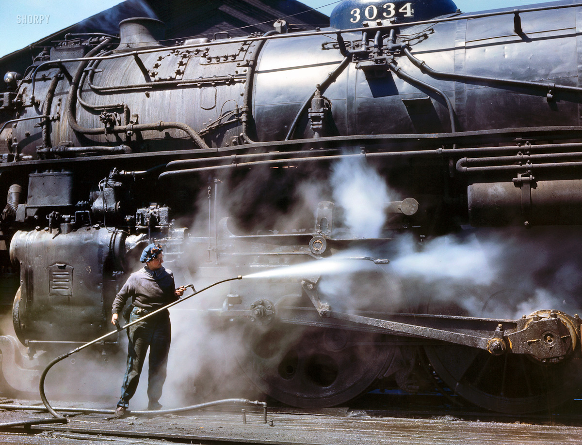

When an engine regularly runs along the coast line it is necessary to spray the seawater off when entering the depot, shed or workshop. After a period of time and planned at the workshop the engines needs to be strapped down to treat the boiler to prevent rust and corrosion to damage the material.
It is absolute necessary to spray the salt of the engine. During spraying of do not spray directly on wheel taps and piston bearers. The water will drip in between both metal surfaces. It is hardly needed to lubricate rods, pistons, wheel pins, wheel taps, more abundantly then usual prior to runs and shifts along coast lines. Grease and oil will stand the seawater and corrosion has no chance.
Much lesser worse is just rain and shower alone, however falling rain will have contain natural composites like sodium and calcium. The mist will have the same effect as rain on its own. When not treated, lime will set at the surface of the engine plates revealing a paling surface at the top layer of paint. In Germany this is overcomes by using bitumen instead of colours.
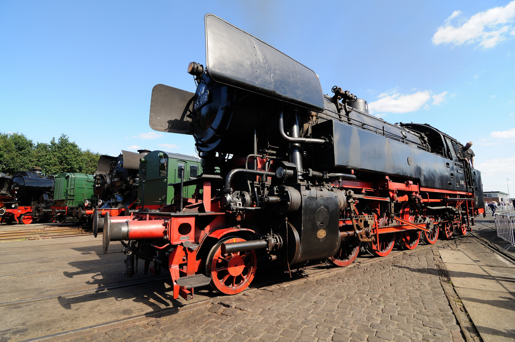
The bitumen gives the German engine the typical black look which is not without a reason. Bitumen is made out of crude oil and water resistant, though it remains important to polish the bitumen surface with oil to get the half glossy shining look on the engine.
Mist and fog will pronounce the coming of more low pressure air fields and area’s that brings in more colder weather. This type of cold is moist and fuzzy and humiliated. The minuscule water drops hazes through the best jersey and sweater and after a while the feeling of cold is present.
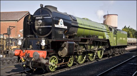
The BR engine 60163 A1 Peppercorn Tornado has its name from these winds.
The wind speeds a natural tornado contains can last up to over 350 mph causing the uppermost severe damage, casualties and injured within the path of the tornado. The most violent winds on earth are captivated in tornado´s. However it is not simulated in TS2015 but in the USA they have to deal with these storms.
Several railroad companies has additional signals operational to warn the driver at an oncoming tornado. It is mostly a flashing white light with an indicator plate on a post.
The driver knows severe winds are approaching and reacts on stopping or slowing down the train. Another signalling system is the use of the onboard radio or GPS Phone.
When a natural tornado strikes, whole trains will be blast of the track and dropped somewhere else far of the spot where they last did appear.. The signal is the tornado warning signal to stop that train and take shelter.


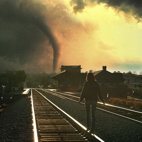
It is of course no need to tell that safety comes first. Though a tornado is not simulated in TS2015, it is still a part of nature’s fury the world has to deal with. Especially the USA has to deal with the issue of tornado’s mostly in the spring time. In other countries tornado’s are rare and appears once and a while but tornado’s do not last long they appear in Europe and mostly the force of the tornado does not exceed the Fujita 1 scale.
4.12 – Driving in weather conditions – Snow, Ice and the steam heating
The coldest moments are the snow and ice periods in the winter. The steam that escaped the chimney will condensate immediately even more rapidly because of the freezing temperature. The effect is seen by the bright white coloured steam exiting the exhaust pipes and chimney.
This is highly visible at the cold lines in Mongolia and China where the QJ’s were stil running at the “JinPeng Pass”. Not only at the Chinese Pass but in all cold countries where freezing temperatures are most of the time remnant. the effect is always present.

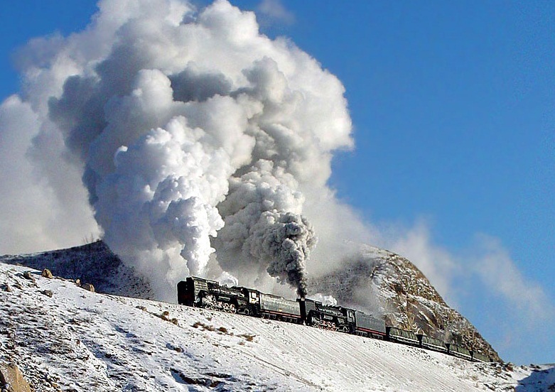
The “JinPeng pass is famous because of the cold temperatures in the winter. This gives spectacular effects when the steam leaves the exhaust, chimney, valves and leaks at the QJ engines as they working to get across the pass.
When freezing cold has set in. The air is mostly bright and only in the morning the fog still hangs around on the surface of the earth. Both nature’s effects has their impact at most steam enthusiast creating the most beautiful images.
Railroads dealing with much snow and ice uses heavy equipment to get the track free of snow and ice. Rotating snowploughs are stored at strategic locations ready to operate. In some cases the steam locomotive assist to get the snow of the track.
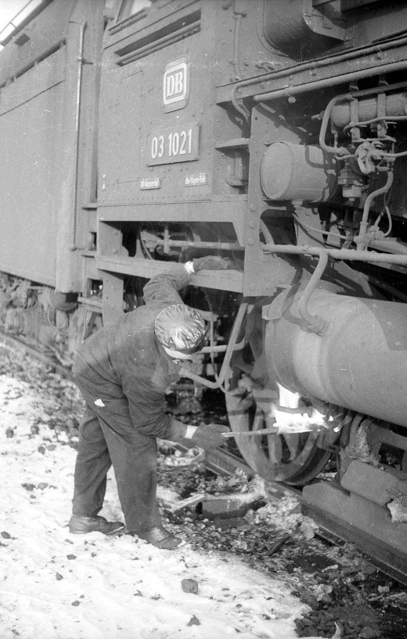
When a shift starts early in the morning the greatest headache is, how to get an engine defrost. Especially when driving wheels are frozen and pistons are under ice
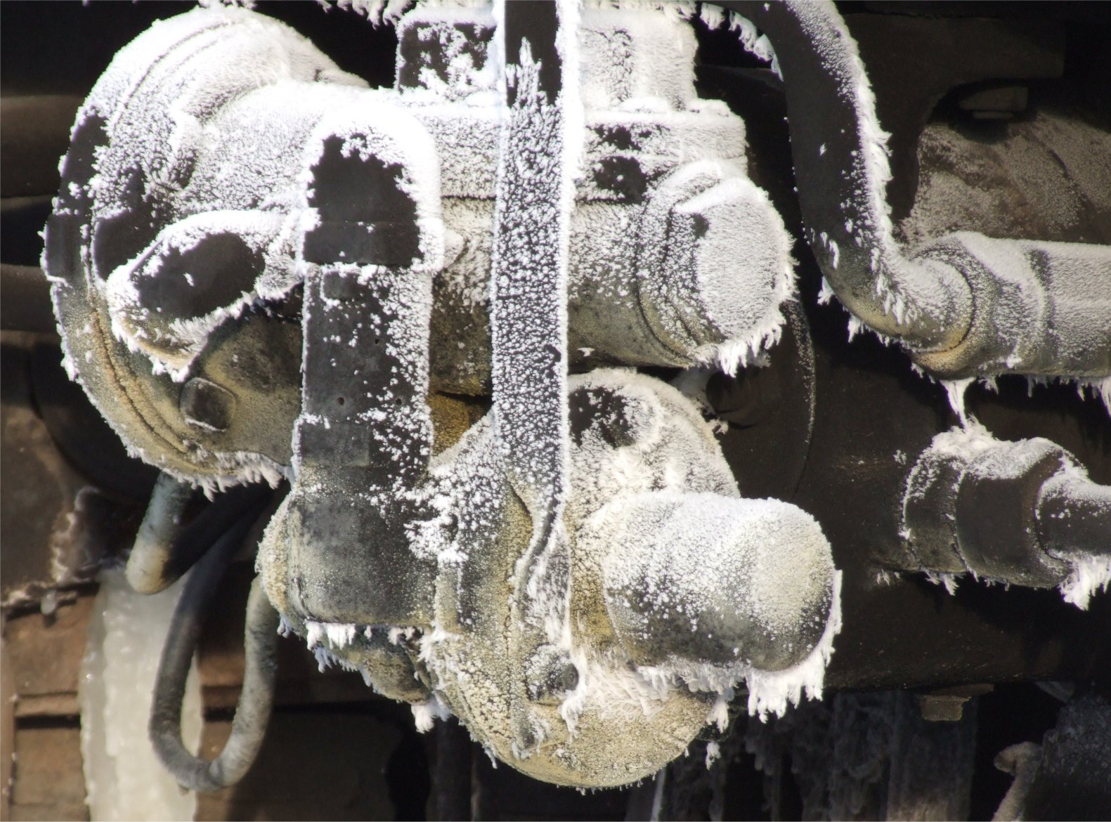
The X-Rot 9213 from the Bernina line steam rotary snowplough is still in service today. Steam here is even better than diesel in this case. Diesel will cloth up when the freezing temperatures are too cold, causing a diesel engine to malfunction. Steam does not have this problem
When the engine get stuck in the snow a special crew has to dig out the engine. After a severe blizzard engines and other traffic will stuck in the snow. It can take hours before an engine is released from all snow and ice. With a shred dripped in oil ignited will melt the snow and ice of the moving parts. The fire will not damage the parts and equipment on proper use.
During runs it is advisable to put on the steam powered heater. A valve in the engine regulates the pressure on the steam heater pipes, hoses and tubes. This will warm the heater elements in the coaches. The steam heater needs to be set and needs time to flow through the whole train. At the end of the train the steam needs to be released though the last valve into the free air.
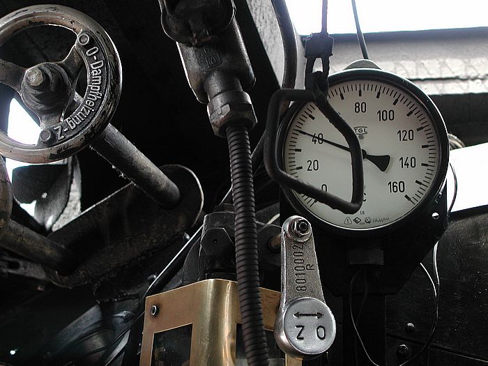
The steam heater valve is at German engines situated at the drivers site on top of the boiler above the air pump valve. Click and drag your mouse and open the valve counter-clockwise. Read out the pressure at the heater gauge which is mostly direct installed next to the valve spindle. When it is freeze outside, open up the steam heater valve and watch if the steam leaks between the coaches and especially at the end of the last coach of the train.
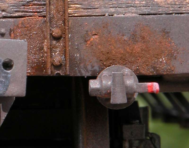

This heating hose is used between two freight cars or coaches who are destined to remain coupled together for a longer period.
The hose is used between wagons but can be replaced by the steam heat coupler. The connection system is widely used in Europe. After the end of the steam era the system remains in use for a long period. electric and diesel engines were equipped with a steam boiler the heat the train.
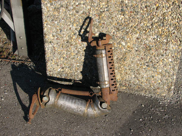

The steam coupler used between passenger coaches and a rack with back up steam couplers.
These steam couplers are simple to install, couple and uncouple it usually remains at the coach heads in between the buffers, next to the air hose and coupler hook


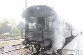

The BDnf for Push-Pull service with the typical steam heater coupler.
In between the coaches and at the end of the train, the steam coupler always leaks and gives a mystical effect.
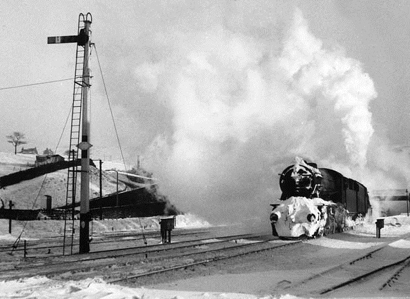
When steam could not escape at the end of the train the steam flow will stuck, cool down and condensate. When it is freezing, the water that is formed by condensation will freeze. Freezing water in a tube, hose or pipe will expand that results in a broken pipe, tube or hose. The steam now leaks out the broken pipe.

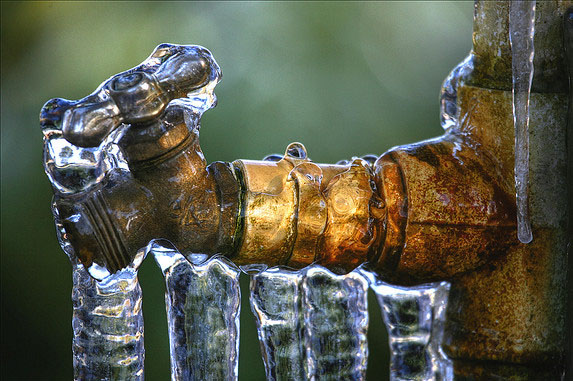
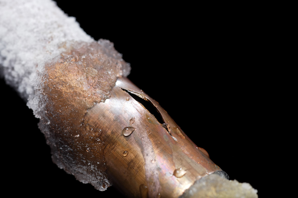
Interpret this situation back to the steam heating pipes. Condensed water is now settled on the bottom of the steam pipe. After a while the same malfunction will occur. The frozen water expands and will crack and break open the pipe. All steam and heat is now leaking out op the gap in hte pipe and steam does not flow to the end of the train.
The avoid any broken or damaged pipe at all, the steam valve at the end of the train needs to be opened up slightly . The steam now escaped smoothly out of the pipes. When the valve should be open up completely, the steam heater would not have the desired effect as it should be. The steam then flows now too fast and rapidly escaped the gap.
The yellow valve bar needs to opened up slightly at the last wagon or coach at the train in order to have the steam heater operational.
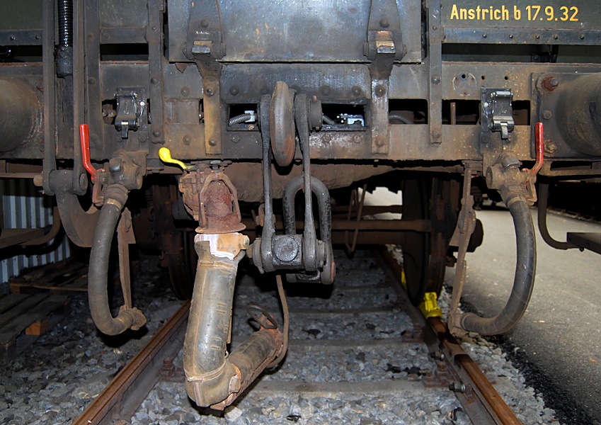


5.00 – Advanced driving
Advanced driving is a special issue you have to manage. To drive these engines you really need to know all the basic efforts of driving steam locomotives. Not only the extended keyboard features and key strokes but also the reality of the exact working of the steam locomotives particularly.
If you become common of the additional operations of the mentioned engines, you are more skilled than ever before.
Enjoy and study the next chapters in order to get the full knowledge of these amazing engines.
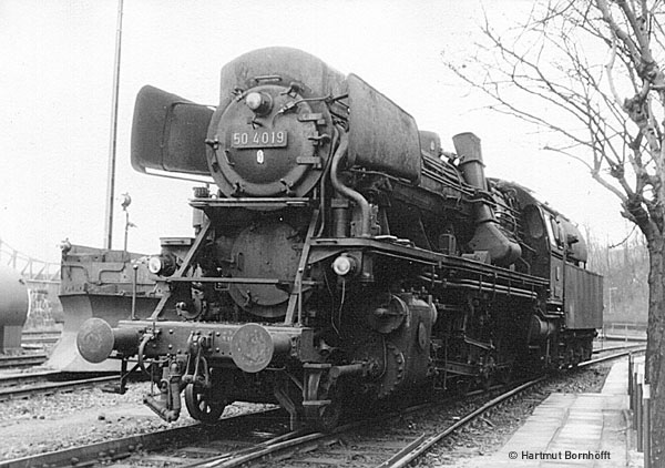
5.01 – Additional firing and driving expertises
Though this guide is based on the Black 5, every engine gots their own specifics and behaviours.
Some of these specifications and behaviours will be mentioned here in this chapter.
It is therefore rather important to read this chapter in order the adjust your way of driving depending the engine you have chosen to drive with.
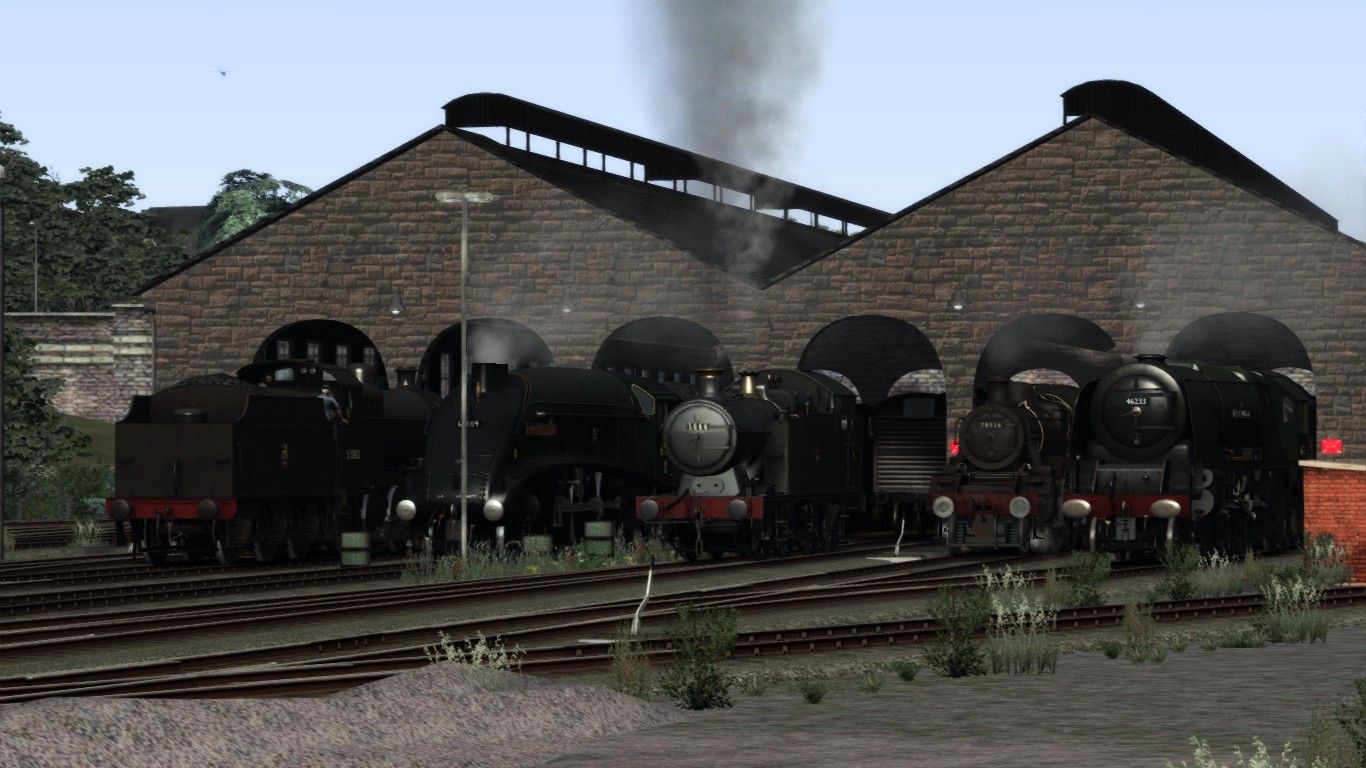
Driving with small loco’s has some additional issues you have to deal with.
This chapter will explain some important issues you have to deal with.
A several engines are build with the drivers stand at the right side of the footplate, even as on some loco’s like the King Class. Now for the European mainland this is not really an issue because some countries drive at the right side like the Netherland, Germany and Austria. Though the the majority drives left while the road traffic is right handed. Countries such as France, Belgium Spain trains drives left handed.
Right handed drivers side:
The blind spot for drivers at the right hand is tremendous. It is hard to see at the left in order to read the signals properly. The driver has often to move from the right to the left to scout the track when the fireman was shovelling.
Reading signalling is part of the run you have to deal with. When you are running in different countries within TS2015. It is necessary to know the country restricted signal system in order to run properly and safe. The main target of signalling is to avoid collisions and accidents.


Keep up the water level but avoid priming.
The coal amount is to be kept at about 55-60%.
Do not forget to open up the dampers.
Depart slowly and gain speed not too fast.
When you set the reverser, mention to press the [ E ] in order to unlock the reverser lock.
When the reverser is in the desired position, do not forget to lock the reverser by pressing [ E ]
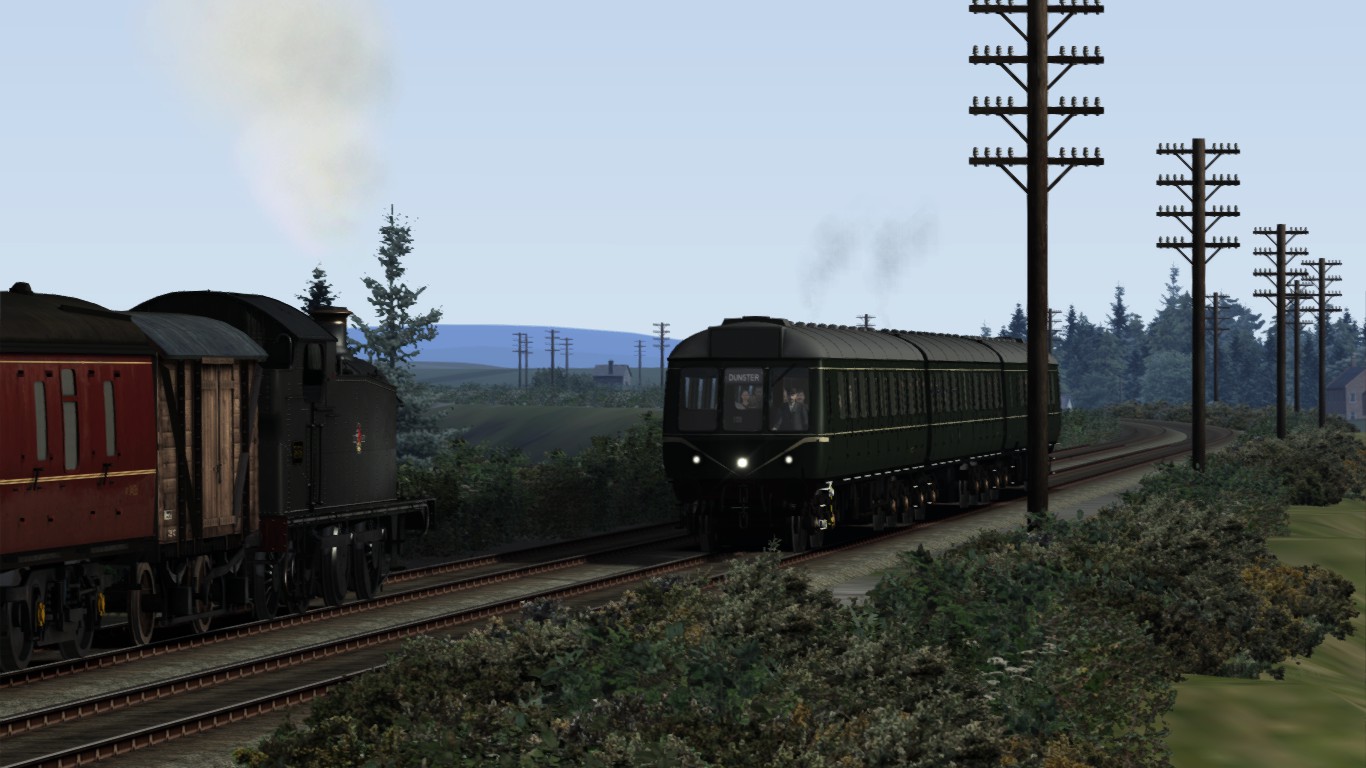

Driving the Challenger or the Big Boy is completely different. The Big Boy has a total weight of 500 tons while the Challenger weights about 350 tons. Stoking these giants is not an manual issue any more because the large fire box is just too large to shovel. However a transportation system in the fire box will provide coal on every spot on the fire grate a well.
In simulation just stoke these engines as normal, but keep in mind the mechanical stoking system these engines has.

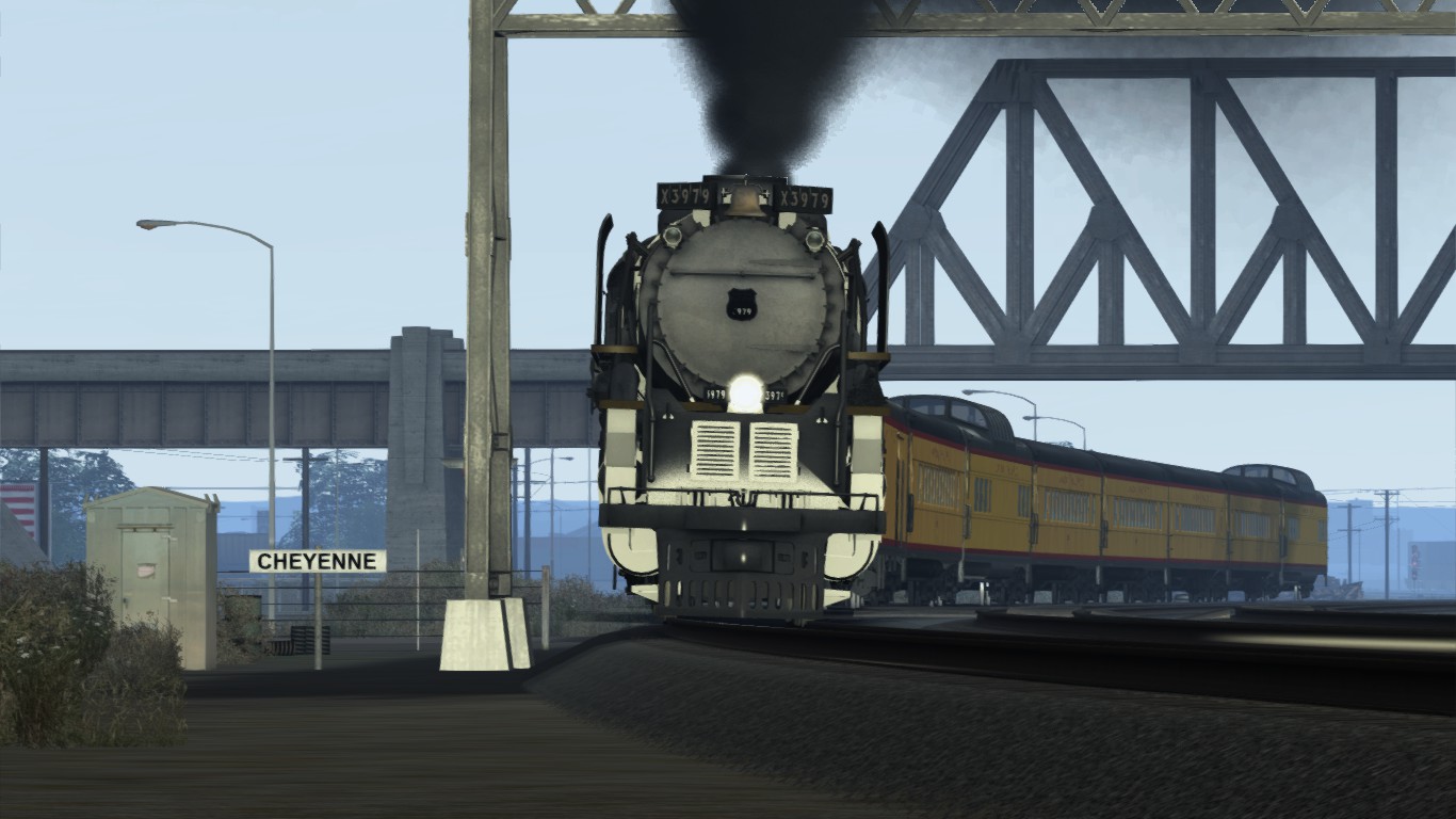
Keep up the water level not decreasing 96% water level. You have to use the injector almost permanently. The US style injector is rather different and uses a lever to open up the water pump. This lever provides either power and either water in one motion and pumps this water into the boiler.
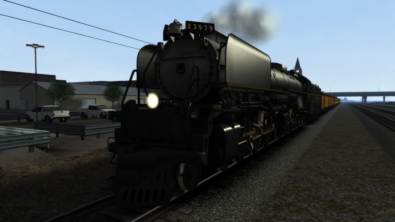
To stop these giants is even more different and difficult a well.
- Cut off the regulator until 20%.
- Position the reverser slowly backwards in reverse and open up the regulator slowly.
- The cylinder now will use the steam power to slow down the train. In some sort of way it acts like a regeneration brake on electric trains. However steam is not regenerated, but rather used as steam brake but direct on the cylinder and pistons. Steam is the main power to slow down directly.
- When the speed has decreased and reached the desired speed or less, position the reverser in the middle
- Set the regulator at about 10% and continue braking using the normal brake system.
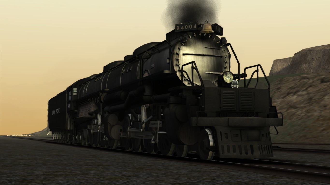
The cab is hugh. Though the most valves and gauges are static.
This image is from the tutorial ride early in the morning.
An Austerity J94 has a simple steam powered brake system. The lever of the brake system will activate a brake shoe which will break down and stop the train quite roughly. This brake is not suited for passenger trains, but for shunting purposes and branch line activities this engine is suited perfectly. The Class 08 and 11 has the same brake facility for shunting purposes, but air is used now instead of steam.
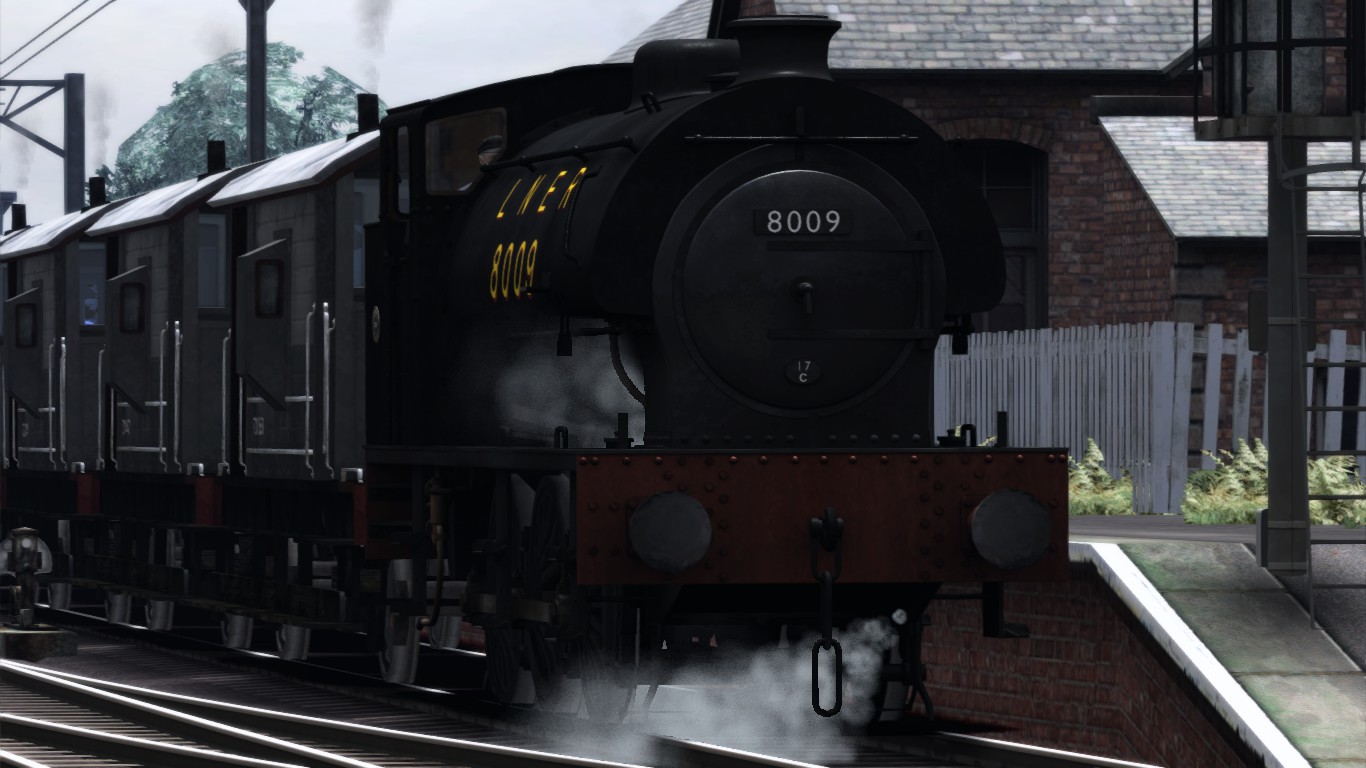
The brake lever is installed just on top of boiler above the regulator lever.
You need some practice in order to the correct use of this particular brake system.
Keep the fire at about 55% and the water level as normal (75%)
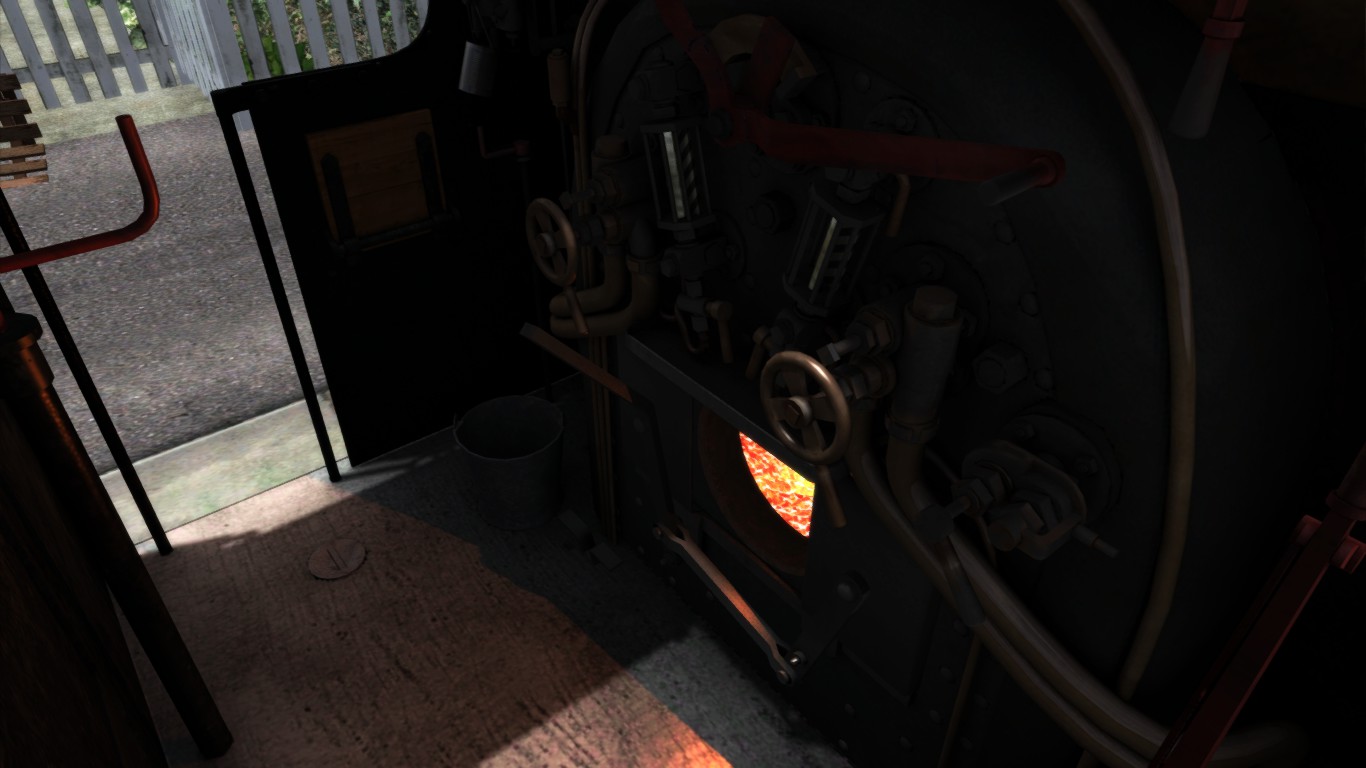
You have to practice this engine quite a while to have the full control and good understanding about this engine. eep the speed low and manage the brake quite well. Manage all gauges and interact on them in the right way to give good care and notice of all things going on at the footplate.
Driving a scaled model engine also requires skills, practice, attention and vigilance.
The engines will haul trains with passengers. Where either it is hobby or not.
These engines needs even more attention while all gauges, levers, equipment is small and tiny and need more careful driving, stoking and handling. The same actions has to be taken as on a original engine, nothing more, nothing less.
A scaled engine is powerful, but more fragile. A 7 1/4 inch Black 5 is capable to haul a train of 10 coaches with passengers. The total weight can last up until 6000 kg. hauled by one single engine (Black 5) It seems ridicules, but it is true. It is a hobby, but still dealing with the same rules and facts as a normal train. Trains that is carrying people around for fun and hobby will not change safety. These mini trains needs attention as well, especially kids are attractive to these model engines and kids does not see the danger, they only see Live Steam engines and trains as a toy.
Scaled engines uses 80 – 110 PSI (about 6 – 8 Bar) on tracks at 5 inch, 7 1/4 inch, 10 1/2 inch
The Romney Hythe & Dymchurch Railway is a major good example of a large scaled mini railway.
The RH&DR is famous al around the world. The engines are even older than the most trains running today. Some of these engines are longer in service than the most steam locomotives ever ran on British soil. They still perform perfectly and are kept in extraordinary condition.
5.02 – The 4MT Standard Class and 6MT Clan Class
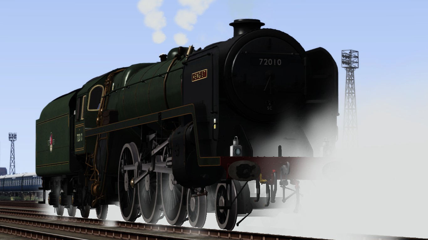
A very special advanced engine is the 6MT Clan class from Just Trains. After the release of the 4MT Standard Class, Just Trains released the 6MT a few mounths later with the same advanced level as the 4MT. Both magificent engines are the best advanced engine ever simulated for TS2015 so far.
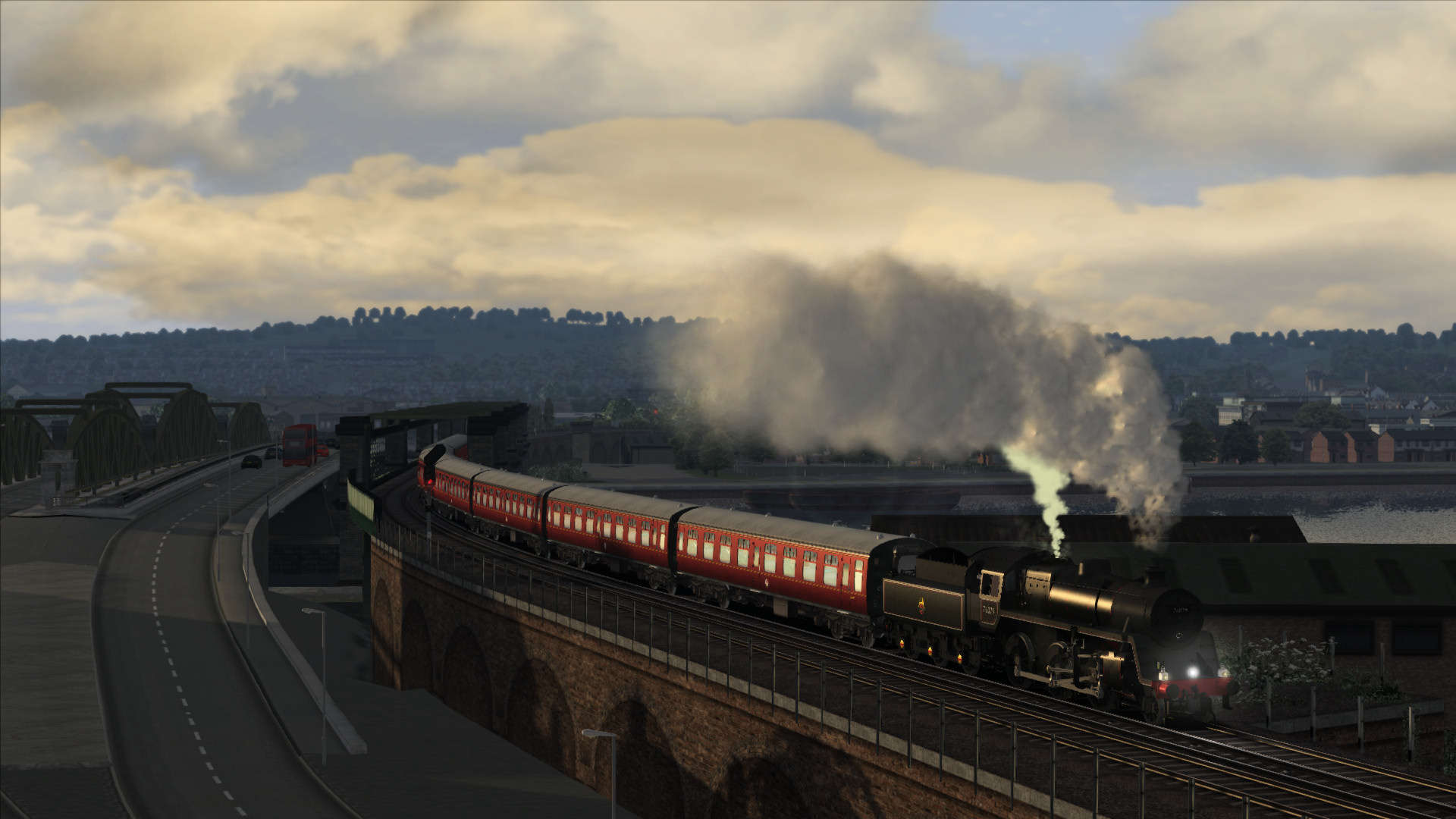
The advanced operation mode of this engine is as closest as possible concerning real driving within the pssibilities of TS2015. It is well worth to have this engine to your collection.
Though JT provides a swapping utility in order to change the advanced engines into the regular engine mode that will ease the opertions to the default mode commonly in use at TS2015.
To gain the maximum control in the advanced mode, you better get femiliar with other engines prior to the use of the 6MT. It is now rather important to have full control using the mouse without the use of the HUD display. The read-outs of the gauges is now more required instead of using the HUD display avoiding any mistakes clicking the wrong controls.
Driving this engine requires the practical and theoretical knowledge of a steam locomotive.
When you have fully read this guide including the specific operational methods of this engine you will be able to drive a steam locomotive as never before. You have to add some more steps which are actually mentioned in this guide.
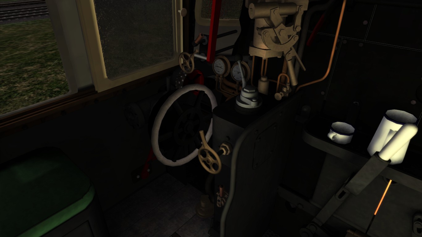
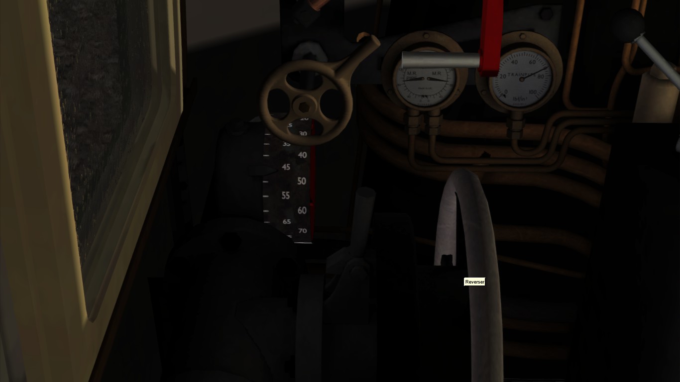
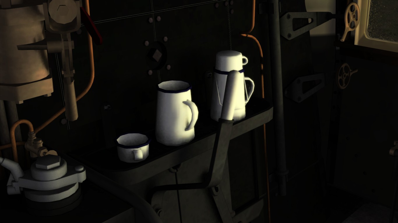
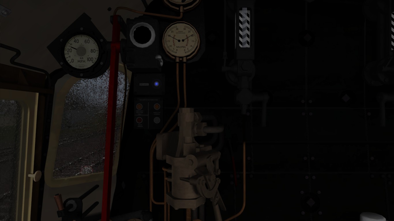
The footplate of the 6MT Clan class is enhanged with advanced operational instruments.
The reverser locker
The reverser is locked by a locker that needs to be operated by pressing [ E ].
- Unlock
- set Reverser
- Lock
The dampers
The dampers are seperately operational by a screw lever. One operates the front damper and the other for the rear damper. At some engines the dampers are operated by one screw lever.
The best position is is to open the front damper for about 50% and the rear damper fully.
This prevents too much cold air to enter the fire grate from the front side while driving.
As mentioned in Chapter 5, Lubrication of motionl parts is required.
When the engine is on a depot make shure you have set the hand brakes by pressing [ / ].
Go now to the right side of the engine using free camview [ 8 ] and aim your view at the lubricator. The lubricator is situated above the “Walschaets” swing, just at the right side of the first traction wheel. Pressing and hold [ Z ] for about 10 seconds. The lubricator is now manually operated and oil is transported to the motional points connected to the lubricator.
The small and large ejector
Above the reverser there are two ejector. A small ejector operated by a small valve adn a large ejector opreated by a wheel lever.

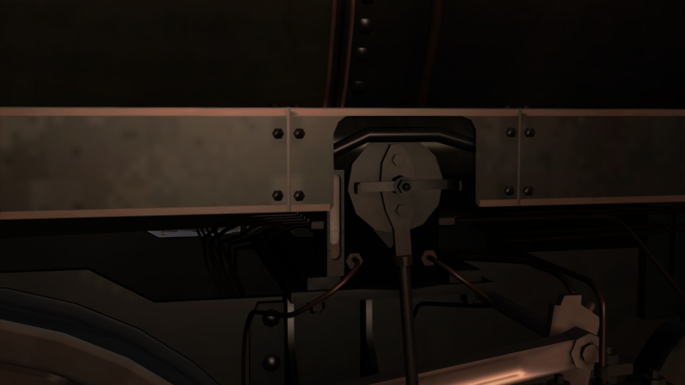
The ash that does not get out of the chimney will fall down on the bottom of the smoke box.
The ash is hot and will keep the heat inside the ash as well. A sprinkler system provides the cool down of that ash to prevent the ash to burn holes on the bottom of the smoke box.
At some depots adn workshops the ash is removes using compressed air. A cleanign rod is linked with an air compressor that blows out the ash. The rod is also to be used to clean out the pipes and tubes in the boiler and is small enough to pass the super heater elements.
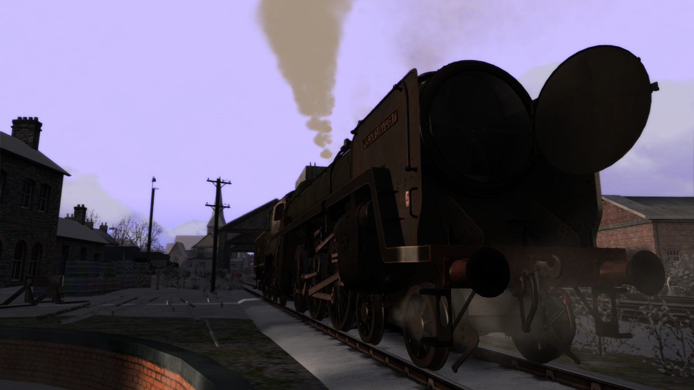
5.03 – The 4MT and 6MT – part 2
To top up the sand press [ Ctrl ] + [ Shift ] = [ X ] to open or close the lids of the sand box at the walk side of the engine.
When the lids are from the sand boxes, press [ Ctrl ] + [ X ] and hold for about 15 seconds.
You see now the sand boxes topping up. Topping up sand does not require to have an extended sand depot as used for the German class 03 and class 95.
Now it is time to conduct a blow down to get rid of all calcuim sediment from the bottom of the boiler. To do so press [ Shift ] + [ Y ] for about 5 – 8 seconds.
- To conduct a blow down at the 6MT press [ Ctrl ] + [ 6 ] to open the smoke box door.
- When the smokebox is fully opened, press and hold [ Ctrl ] + [ Shift ] + [ 6 ] for a while.
- Close the door by pressing [ Ctrl ] + [ 6 ]
Conducting a blow dow should be done regularly with a frequency of about 20 minutes, only at depots, on passing bridges or between stations.
The head lights
The head light can be operated manually using the combination [ Ctrl ] + a number
puts the head light in place.
To put the lights in place press [ Ctrl ] +
- [ 1 ] Left under
- [ 2 ] Middle under
- [ 3 ] Right under
- [ 8 ] Top light
Refer for the train classes and head codes to the Beginners guide to model railway goods service[myweb.tiscali.co.uk]
To drive the 6MT you need know how to operate the reverser and regulator as mentioned in this guide. Additionally: operate the regulator with small movements at a time and keep the balance with the reverser in order to make steam.
The amout of fire should be kept at about 1500 Lbs.
Keep an eye at the water glass and watch the simulated flowand wanking inn the glass when driving. when the trin stops the water lever appeares to be low but after the stop the water is flowing.
After a run top up the supplies and move on to the ash pit to rock the fire to get prepared for the next run. When you came to a stop at the ash pit, look to the bottom next to the fire box of the footplate. At the edge of the fire box there two black metal rod holders.

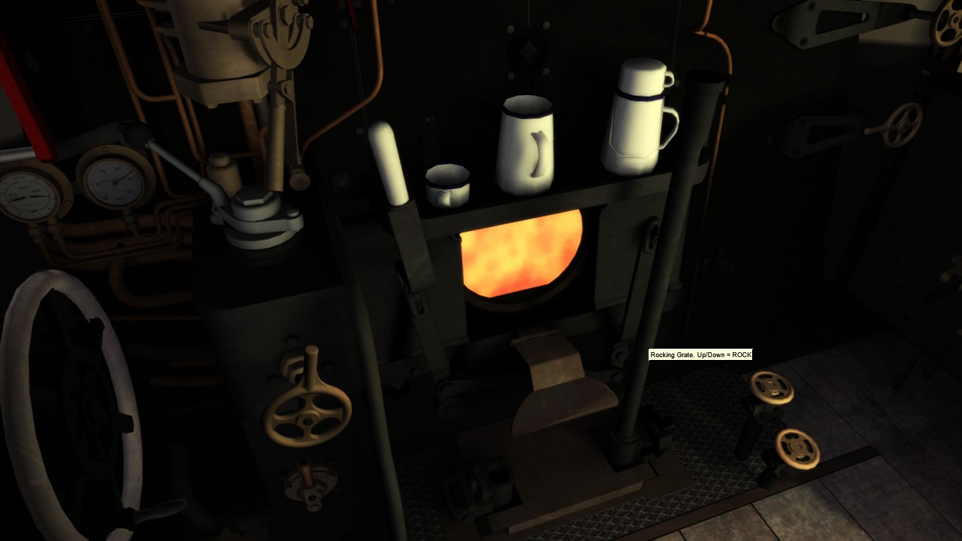


- Clicking on the right rod holder puts a rod in place.
- Now grab the rod by click and hold the rod .
- Move the moue up- and downwards or press [ Ctrl ] – [ R ] the rod now is moving with the movement of your mouse.
- When ready click on the rod holder again to store the rod.
- Now you do the same by clicking on the left rod holder.
Use now the mouse or press [ Ctrl ] – [ L ]
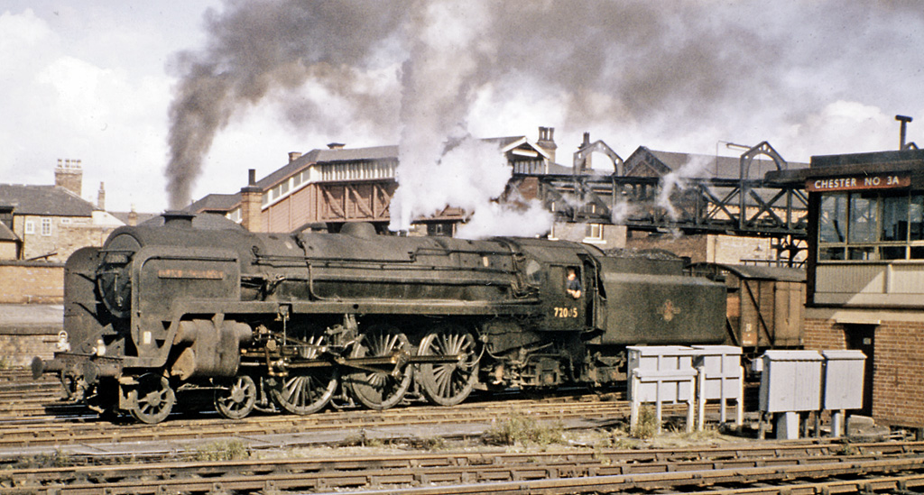
5.04*** – The 5MT Standard class
This chapter is in preparation
5.05 – The 5MT Standard class – part 2
This chapter is in preparation
5.06 – The 7MT Britannia Class Advanced from Just Trains
The Britannia Class is one of the famousest engines in Britain. However the package is not released yet, we still espect the arrival of the magnificant engine soon by Just Trains.
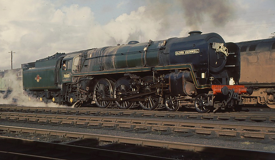
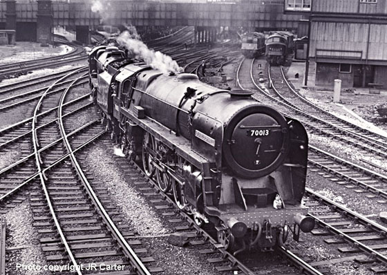
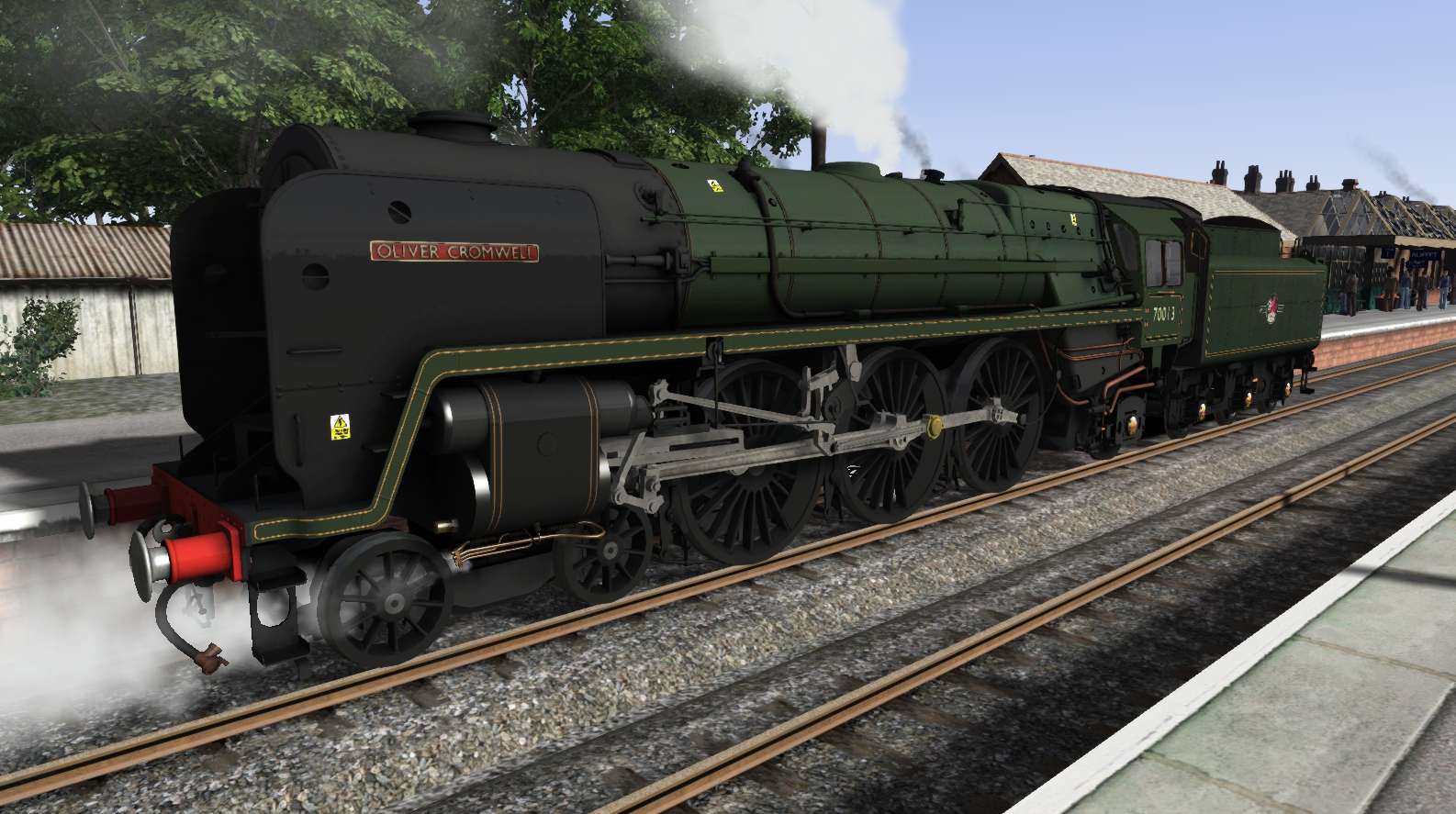
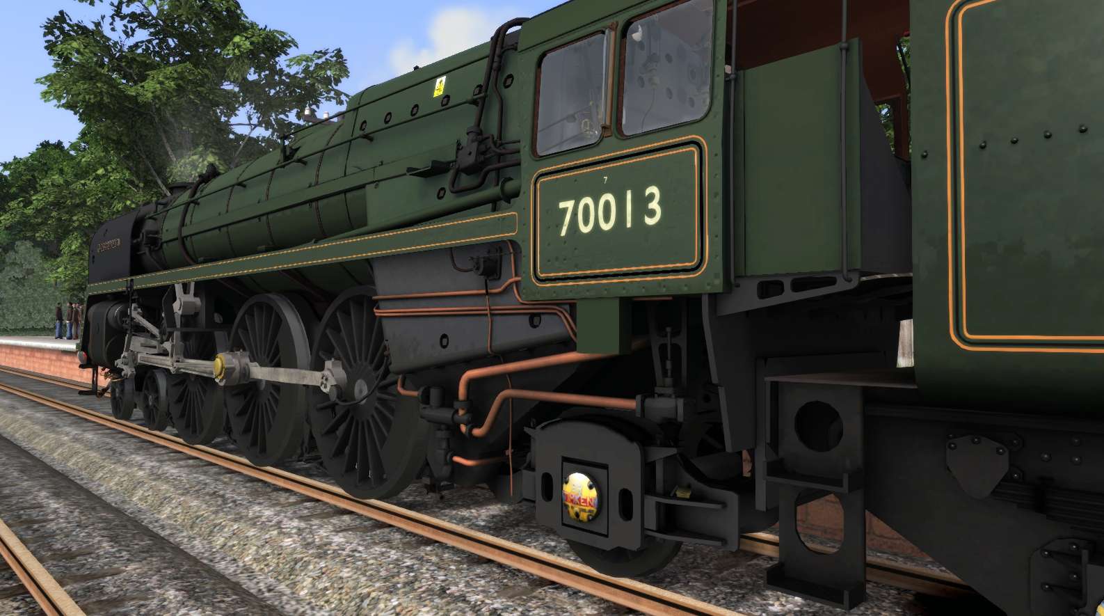
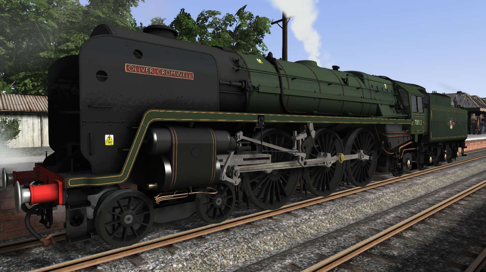
5.07 – The 7MT Britannia Class driving
This chapter is reserved .and will be used after the release of the Just Trains 7MT Britannia class
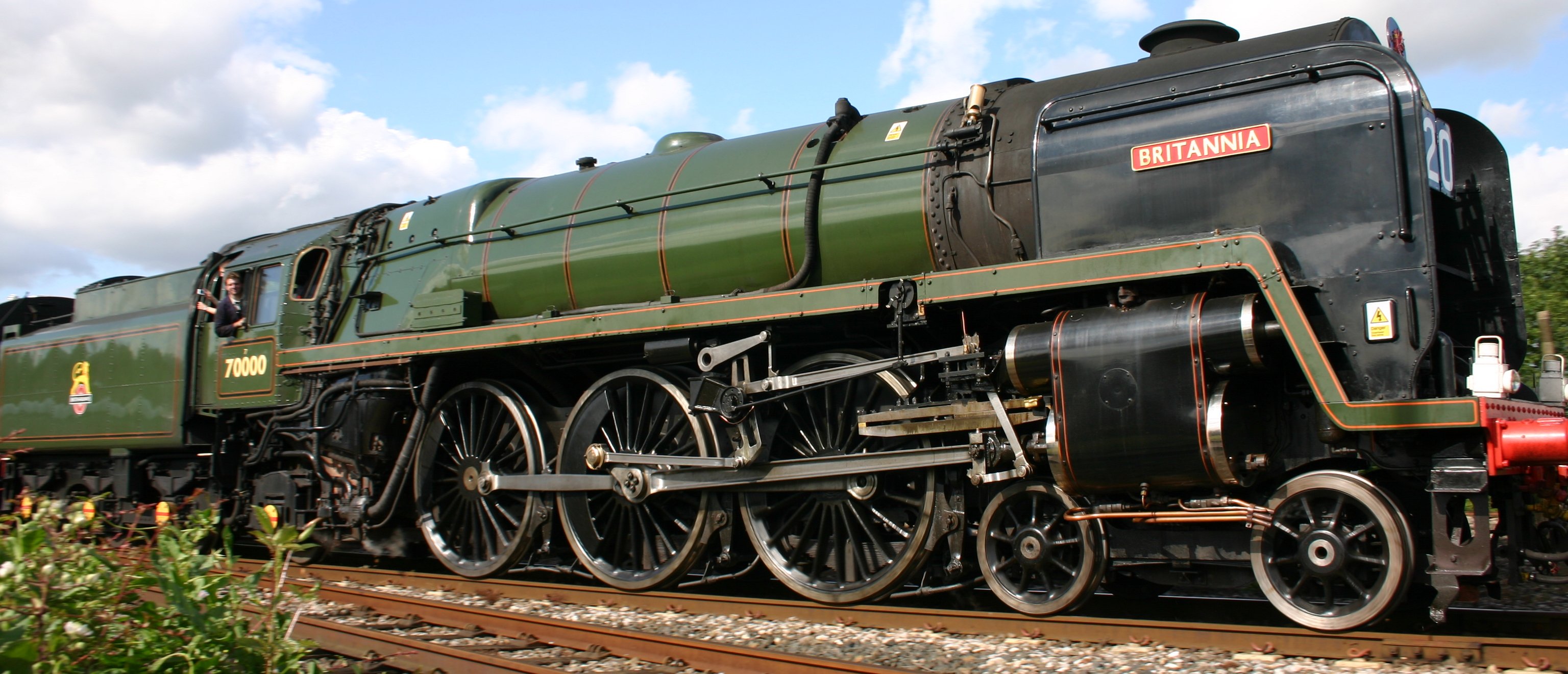
5.10*** – The Riviëra line in the 50’s, King, Castle, Grange and Pannier
This chapter is in preparation
5.11 – Driving the Bulleid Q1 – The history
In late 1939, the Southern Railway, until then primarily a high-density commuter railway serving London and South-East England, found itself on the British front line of WW2, with a severe lack of modern freight handling capability. The aesthetical design of these “ugly” and “nasty” engines are highly unusual and even the controversial design of these engines became rather an outsourced engine.
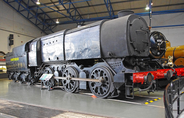
The Bulleid Q1 at the NRM, York, England
However the design did not win the contest of beauty, the engine were powerful enough to haul a whole freight train and were created in the WW2 and later as part of the Austerity project. A project that was spread out all over the allied countries of Europe after the end of WW2. However none of these engines has been made for other countries then Britain.
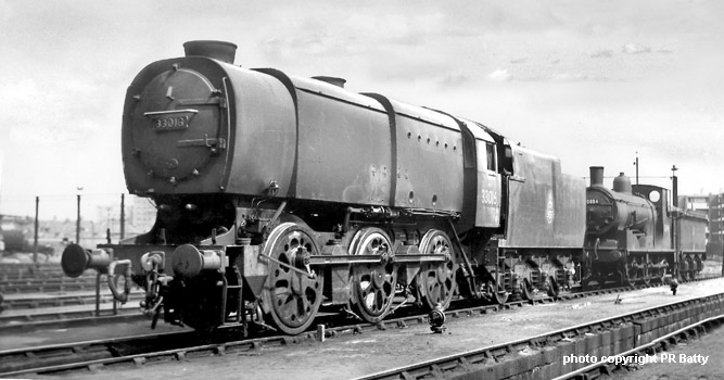
The highly unusual and controversial design represents the ultimate development of the British 0-6-0 freight engine, capable of hauling trains that were usually allocated to much larger locomotives on other railways. Among other nicknames, the class were nicknamed as “Coffee Pots” or “Charlies”
The unusual shape was also dictated by the use of materials; the lagging was made of a glass fibre insulation material known as “Idaglass”, which, although cheap and plentiful during the war years, could not support any weight, and therefore a separate casing was required which followed that seen in the Merchant Navy class locomotives, and the boiler rings were adapted to lend the lagging the support needed. A copper, rather than steel, firebox was utilised, unlike Bulleid’s Pacific designs. The wheels were smaller, 5 ft 1 in (1.55 m) adaptations of the Bulleid Firth Brown type utilised on the Pacifics. The locomotive had two cylinders with Stephenson link outside admission piston valves, having a travel in full gear of 6 1⁄8 in (155.58 mm) and a steam lap of 1 5⁄8 in (41.28 mm).
The Q1 represented the final development of the British 0-6-0 main line steam locomotive. Later designs of medium-powered freight locomotives, such as the LMS Ivatt Class 2 2-6-0 and LMS Ivatt Class 4 Moguls all had a 2-6-0 wheel arrangement; the 0-6-0 wheel arrangement was not used again in the BR Standard designs of locomotive. BR classified the Q1 class in the power classification 5F. This represented a rarity, as few other 0-6-0s exceeded the classification of 4F, with notable exceptions being the LNER Class J20 (5F), LNER Class J39 (4P5F) and LNER Class J38 (6F).
The Q1’s route availability meant that although they were primarily freight locomotives, they also frequently deputised on secondary passenger services. However, the class gained a reputation for poor braking on unfitted freight trains due to the light construction of the tender braking system. The Q1s thrived on their intended duties during WW, where the class had proved that they were an indispensable addition to the Southern locomotive fleet. This was achieved to such an extent that they all remained in service until the 1960s, long after they were intended to cease operation as an “austerity” design. Withdrawals began in 1963, during the implementation of the BR Modernisation Plan which saw the end of steam operations on Britain’s railways, the last example of the class being withdrawn in 1966.
Not only the Q1 was a controversial design of Mr. O. Bulleid, but also “strange’ designed diesel engines were part of the work of Mr. O. Bulleid.
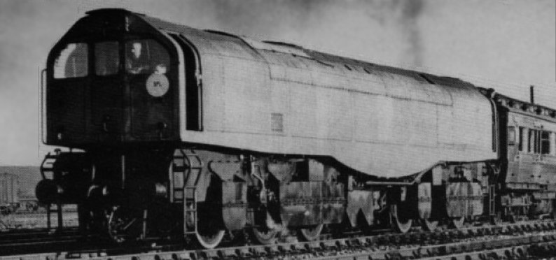
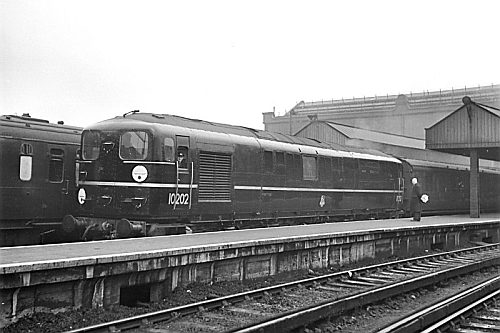
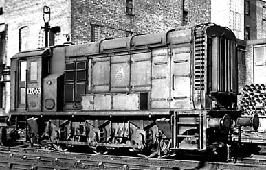
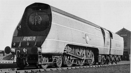
The even controversial design of a chain driven steam dividing system was build into the Light Pacifics.
5.12 – The Bulleid Q1 – Driving in practice

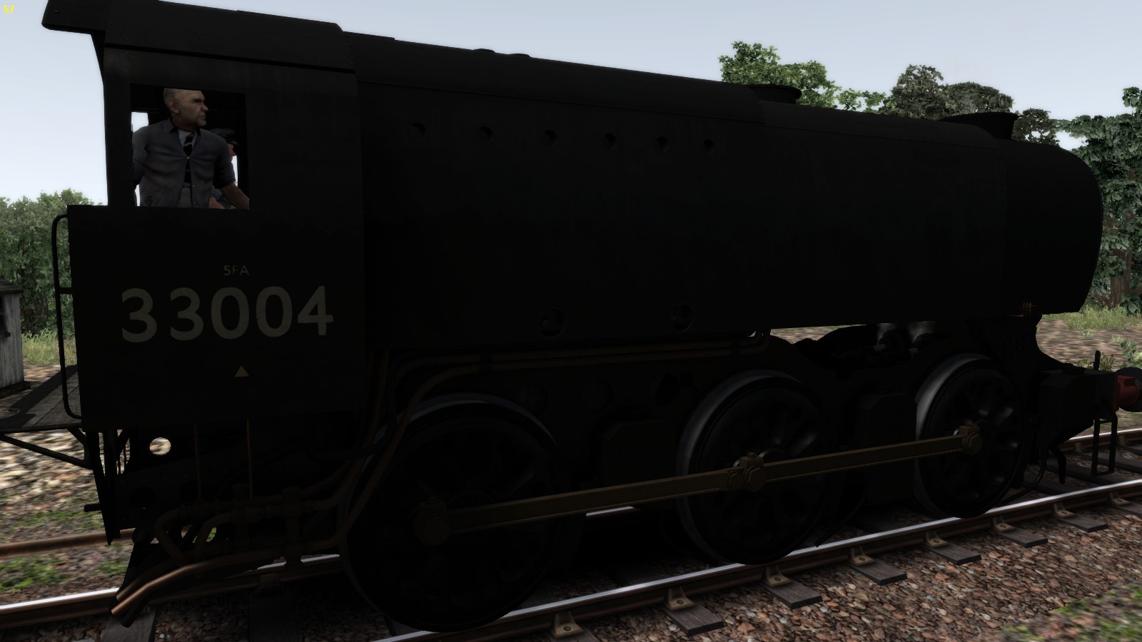
Driving in expert mode by pressing [ Ctrl ] – [ A ] gives you the full controls of the lubrication and sander, front and rear dampers. To get the full air though the grate pull both lever up.
Before you set off. Open the lubricator by turning the steam valve that let the steam flow from the boiler to the lubricator. This valve is situated straight above the regulator. Open the valve counter clockwise.
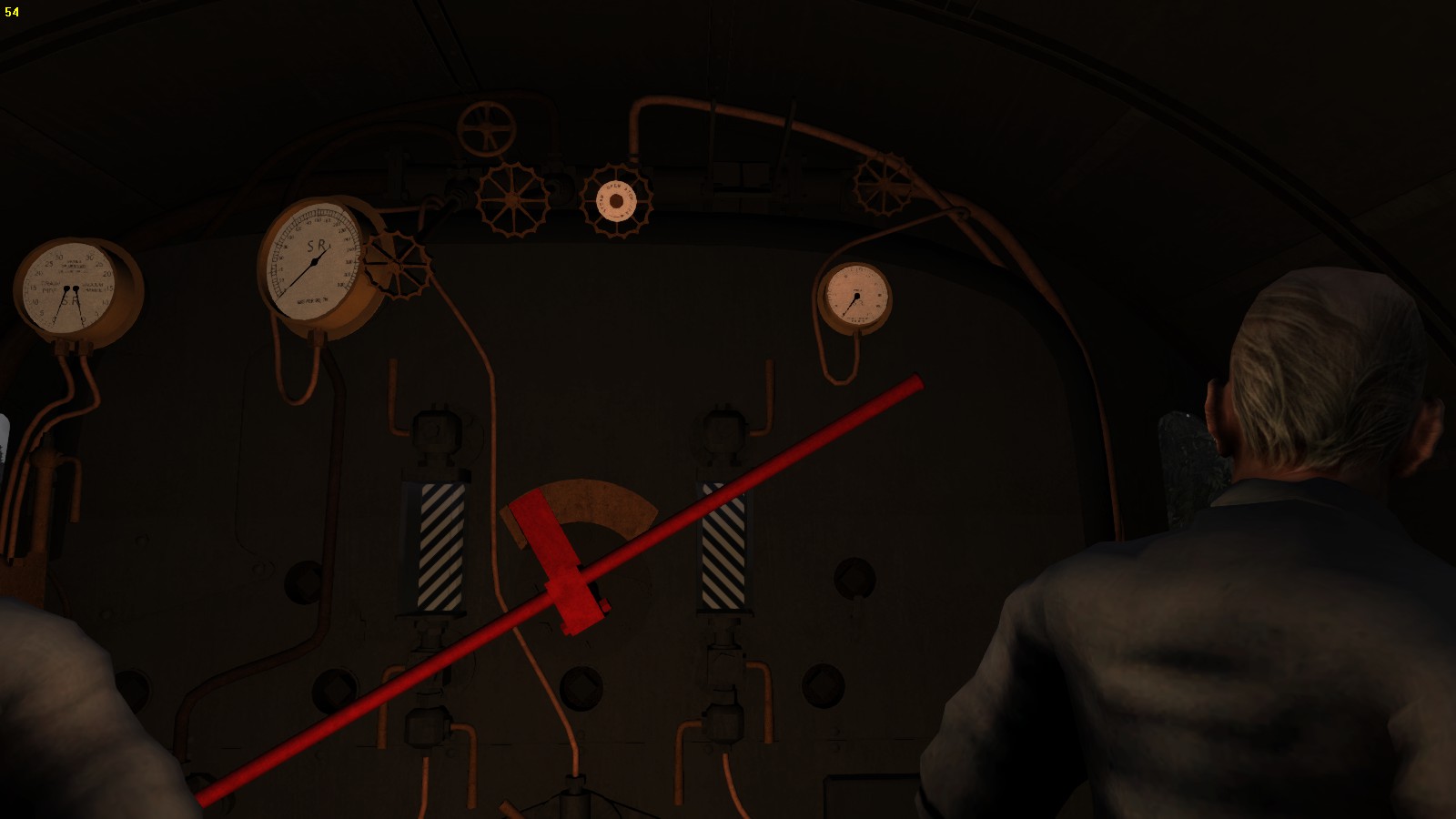
Open de steam valve to feed the sander counter clockwise. This valve is situated at the left of the lubricator valve.
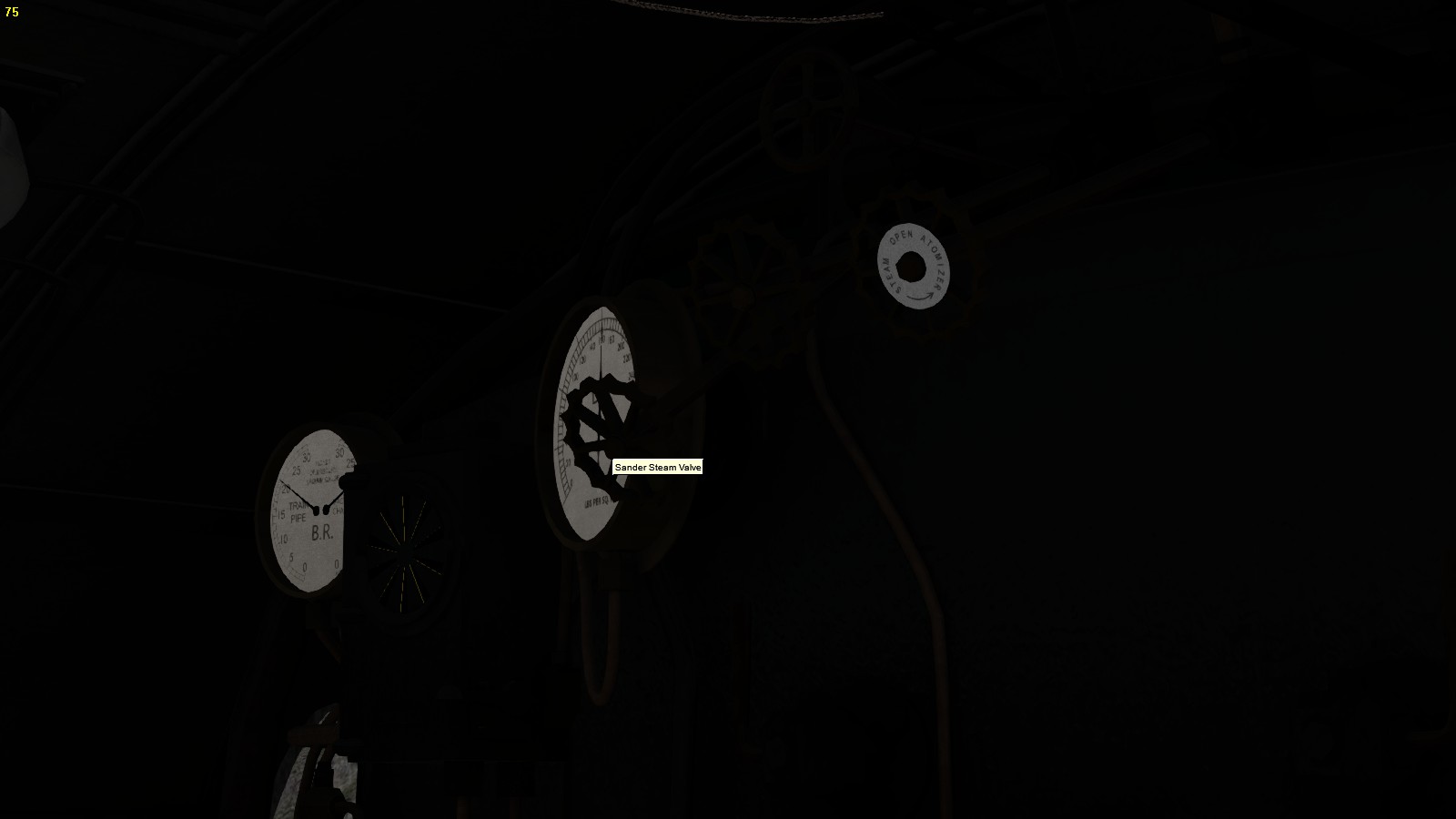
The first engine with a good view on the fire grate is this Q1. Place yourself in the cab and use the [ Arrows ] to move around the cab until you see the fire door and fire grate.
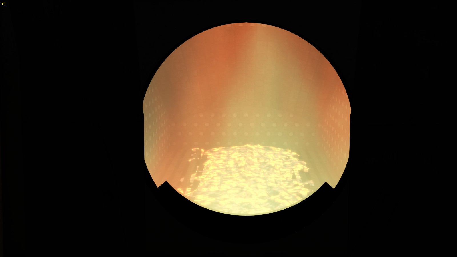
The view is nice, but far form realistic firing. In practice the fire grate may not be visible. At the fire box sides the amount of coal should be at least 3 times the amount as visible in the middle. Under the fire door this amount should be 4 times the around as visible in the middle. Then you have a good and well prepared fire.
Be aware of the lack of the engine brake. Drive carefully and slowly and adjust the amount of steam properly. Use your handbrake to slow down the engine.
When driving a train you now will discover how hard it is to brake the train properly. To overcome this, slow down much earlier. When necessary, set the reverser backwards and open the throttle. This will help to slow down. Use the train brake as usual and adjust the brake force by using the hand brake until you have stopped.
5.13*** – Driving the 2F Dock Tank
This chapter is in preparation
5.14*** – The LMS 3F Jinty
This chapter is in preparartion
5.15*** – The BR-LNER J50
This chapter is in preparation
5.16*** – The GWR Small Prairie 4400
This chapter is in preparation
5.21** – The German Class 86
This chapter is in preparation.
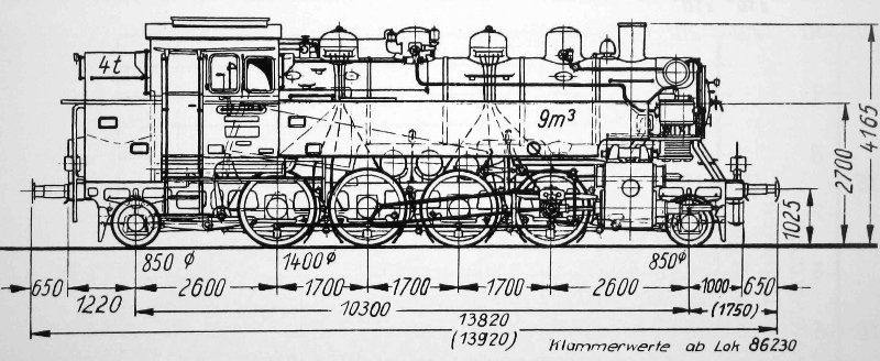

Only 2 engines are still unaccounted for (86 016 and 86 469). The BBÖ/ÖBB began to scrap them as early as 1945, but the last pieces were finaly scrapped in 1972. However the Austrian engines had some of the most spectacular duties, including working double-headed on heavy, empty, ore trains with a DRB Class 52.
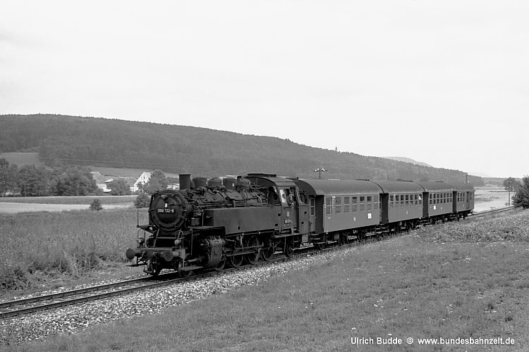
The German Federal railroad (Deutsche Bundesbahn) stationed most of its 86’s in the area and region of Nurnberg for the Franconian branch lines to marshalling the yards in that region. The locomotive shed at the city of Hof, Germany close to the former border of the DDR was also renowned Class 86 territory. Short, semi-fast trains were also regularly hauled by the Class 86. The DB retired its last one in 1974.
In the DDR (Deutsche Democratische Republic), the 86’s were mainly stationed at Aue engine shed (with over 50 engines) for the surrounding Erzgebirge routes. Some DR engines stationed at Heringsdorf shed and on the island of Usedom were even given smoke deflectors.
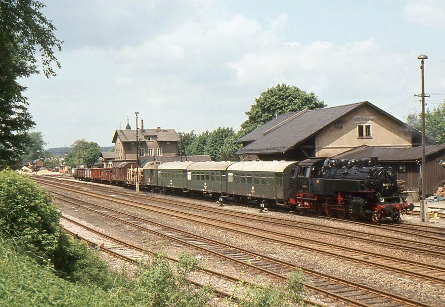
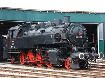
Since 1999, no. 86 001 was being preserved. No. 86 1056 met a tragic end in 1989 when she was the last victim of the GDR’s scrapping madness and was converted into a mobile steam dispenser. Its driving gear and cylinders went into the furnace.

Driving the class 86
5.31*** – Driving the vR E03, E10 and E40 Expert Line
This chapter is in preparation
5.32*** – Driving with the German PZB / Indusi system
This Chapter is in preparation.
5.41*** – German rolling stock in the steam era.
This chapter is in preparation
5.51 – Driving the UP FEF-3
The Union Pacific is one of the most beloved railroad companies in the world. Not only because they have remained steam into heritage preservation without ceasing some magnificent engines. but also because they ran the biggest of the world. The Big Boy was with 500 tons the greatest and heaviest engine ever created. The smaller 3985 4-6-6-4 is still in service and run throughout the USA for steam specials together with the FEF-3 844 4-8-4 and since short the 4014 is brought to Cheyenne for restoration in running conditions. When this engine starts to run this will amaze the whole world again pulling train and steam enthusiasts from all over the world.
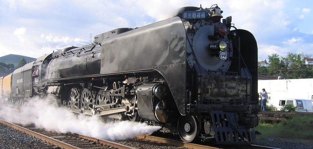
The store released the FEF-3 Northern wheel arrangement 4-8-4. The original now runs throughout the USA, this engine never ceased service even as the Challenger. It seems strange but the engine is NOT a museum engine. Though steam fanatics and the input from the Union Pacific keeps these giant alive together with the 3985 and some other preserved engines in the sheds in Cheyenne. The steam locomotives are still the Union Pacifics jewels in the rail business and always admired by everybody seeing these magnificent engines running today. Even the company itself is proud to keep these engines preserved and in running condition.
A “new” engine is set for restoration. The 4014 has been brought back to Cheyenne and will run again after restoration. A hugh engine and a hugh desire of almost every rail fan to have one Big Boy running again, and now the hope became fulfilled. A Big Boy is now in restoration.


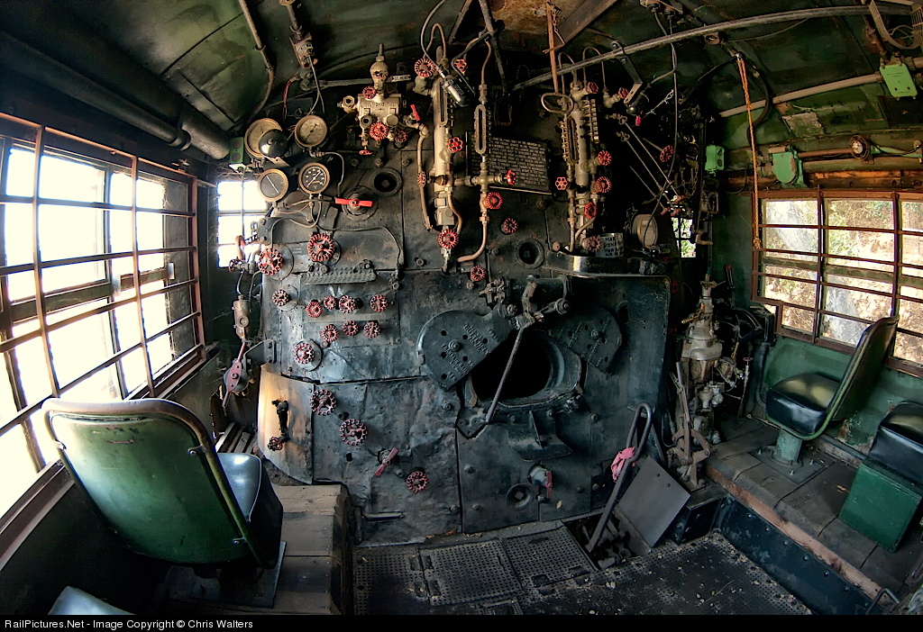
The Big Boy cab is hugh. Though the 844 is an oil fired engine, the 4014 uses coal firing using steam pressure to “shovel” the coal automatically. The fire box is too large manual firing and stoking, but a fire door provides the possibility to adjust the coal bed by manual shovelling.
The engine is the first DLC within the store that comes with the most valves and levers in the cab fully functional. Even the water scopes can be tested. Now we are start to move in the right direction.
The engine comes with a vast list of short cuts, but now to drive this amazing engine in advanced mode you have to forget the HUD completely and the best way to drive this engine is using the mouse to drag the lever in combination with the short cuts that is included in the manual itself.
Driving in advanced mode requires true skills and the knowledge how to deal with a oil fired engine. Before you set of it is recommendable to read chapter 12 of oil fired engines. Be sure you have some knowledge when you start to run the FEF-3 And even still drive in expert mode and no HUD ! Never forget the HUD was never installed at steam locomotives either in the days of steam.(Though wondering how this should look like.)
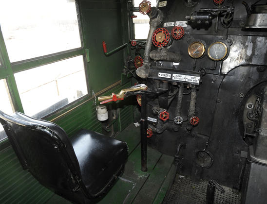

The cab inside the 844 is hugh, all instruments are ordained and properly maintained.
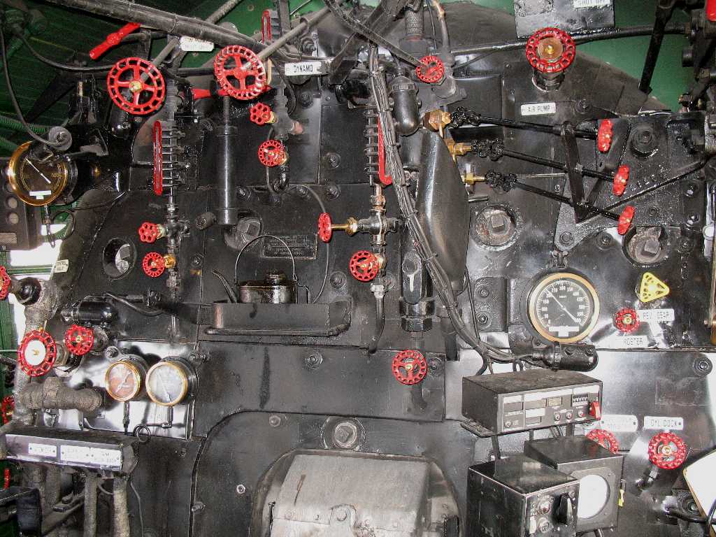
Cabin Top view including the water scopes which can be proven and tested. Taking a closer look, you will notice the next operating instruments and levers. The speedometer with the remote control partly visible for the diesel engine at the left. Above the speedometer, the radio stack.
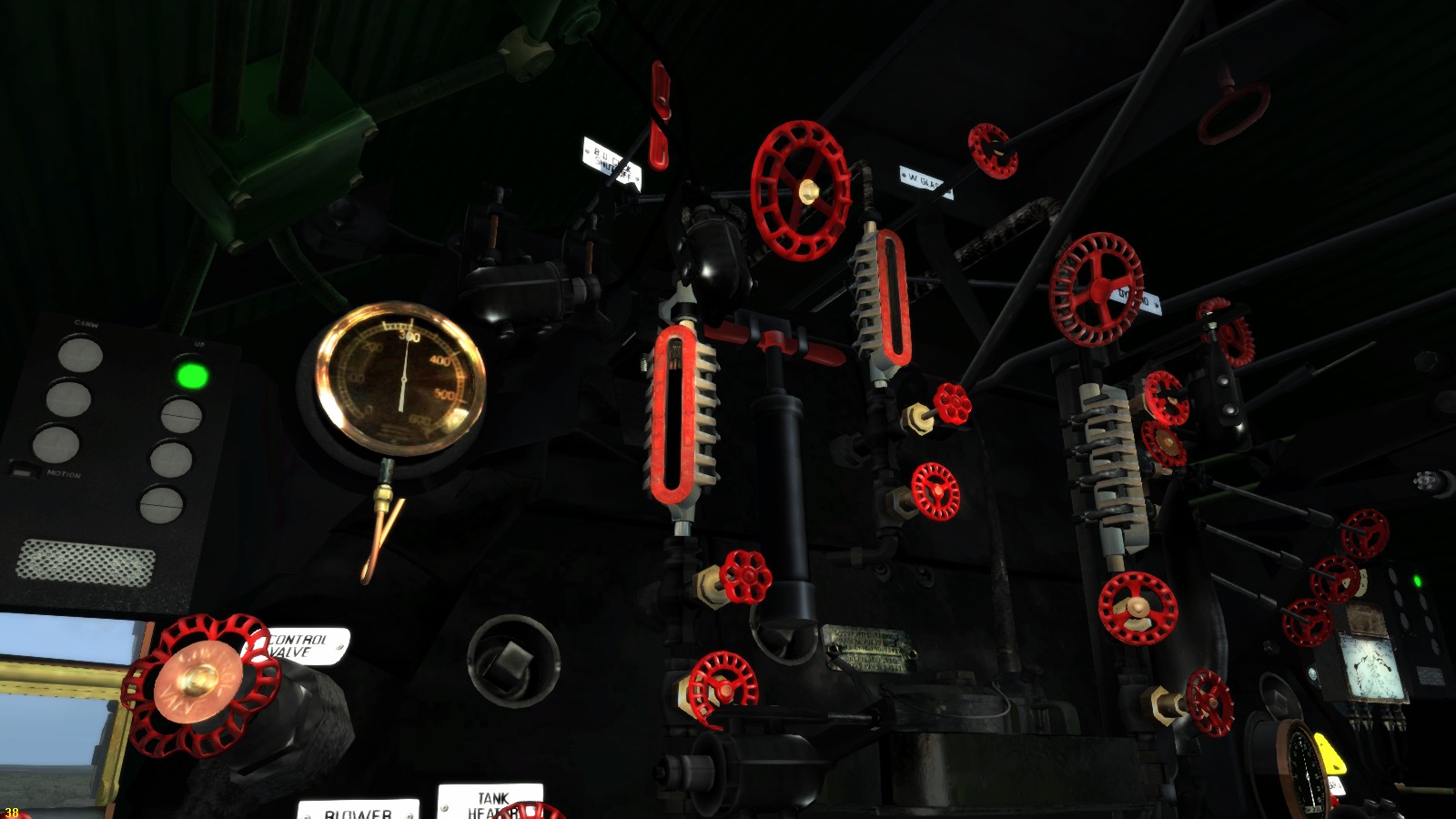
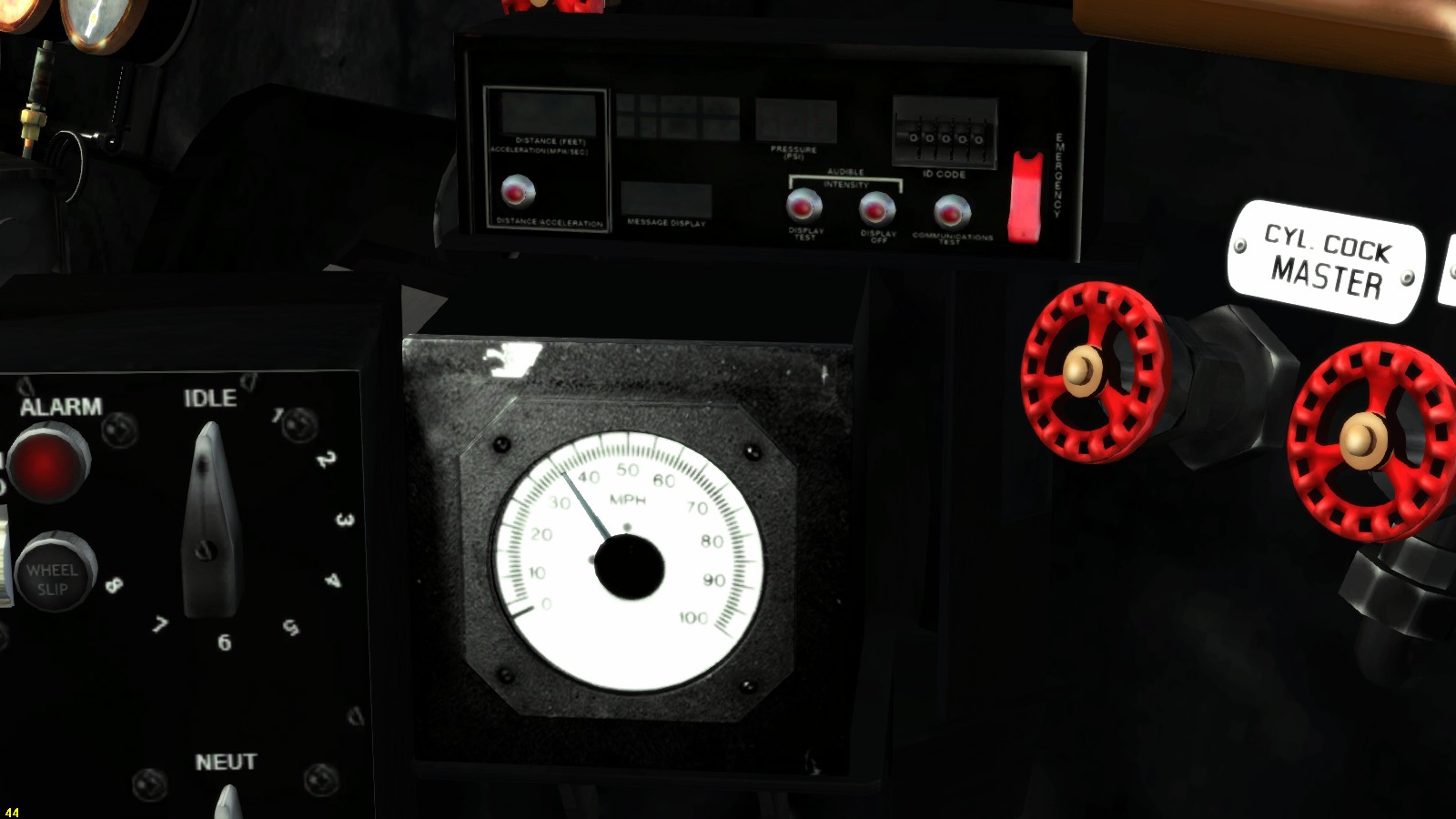
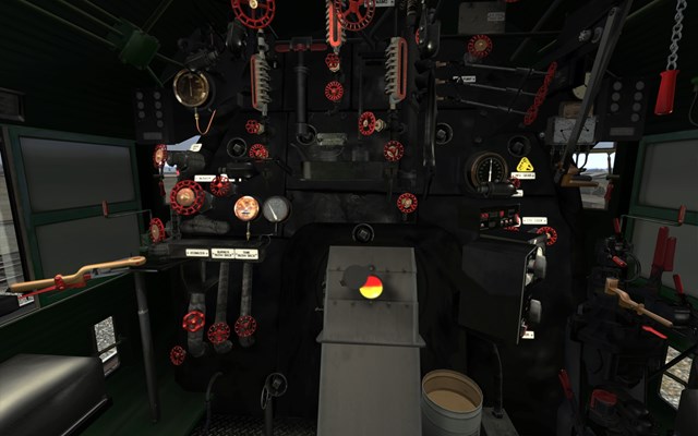
After you have red chapter 12 and having some experience with running a steam locomotive You now are quite ready to take your skills up to the next level.
Probably you have driven the FEF-3 with the HUD display and simple mode, but after all you will be in expanded advantage when running as professional as it could be.
The way of driving is not very different then a common engine however you have now to get common with the extra features this engine is equipped with. One of the main important features that is operational is the firing method. The firing method is rather different. Now you can check the HUD by pressing [ F4 ] and notice the coal amount at the firebox door.
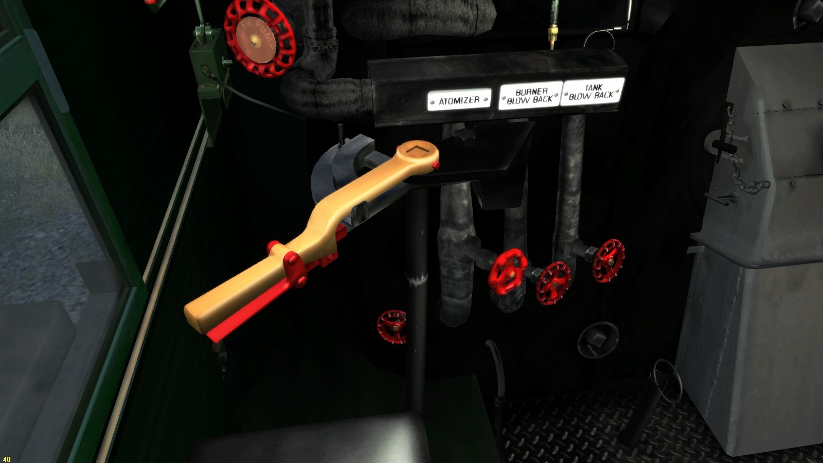
The fireman’s side shows some important instruments here.
The regulator for the oil flow to the atomizer. The directly to the right three knobs that operates steam valves. A steam valve to pressurize the atomizer that sprays the oil into the firebox. The oil will ignite because of the temperature creating a massive flame.
Also a knob to operate the oil heater into the tender. The oil needs to be heated to get it liquefied. As you have notice, the oil needs at a certain temperature to get a proper oil flow to the atomizers. Another knob that operates the valve for the tank flow back.
Drag your mouse over the valve knobs and levers to see which function the knob contains. There are also short cuts, refer to the manual for the short cuts.
Open the water scope valves at the right site just behind and above the regulator. There are three knobs in range next to each other. After opening, watch the water scopes to be filled. Turn the knobs underneath the water scopes to test and seen if the water scopes release the water out of the scopes. If so close the water scope valve and see the water scope filled again. If this test is passed the water scope are functional. Now in practice a water glass could break, A steel ball mostly ball bears are in use for this purpose is fitted in the waters glass bearers at the top and the bottom bearer. The water causes the balls to sink down. Steam presses the balls into a funnel shaped fitting and closing down the steam flow though the broken glass. The upper fitting contains also a spring to press the ball unto the gap. in the top water scope fitting. When a water glass brakes, close the valves of the water scopes and replace the glass. The balls prevents a dangerous steam flow into the cabin.

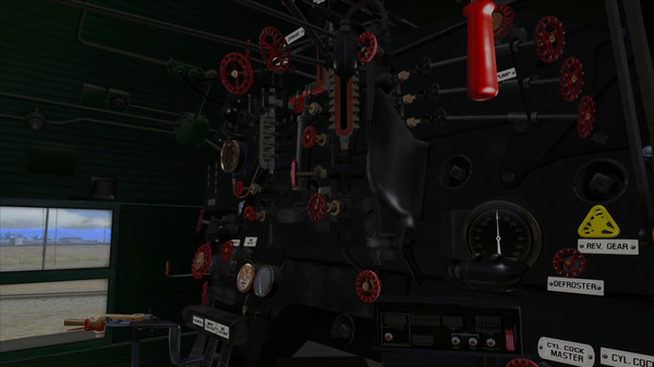
Open the blower valve and regulate the blower as usual as you became common with.
This operation is not different as on a coal fired engine. Open the atomizer valve and watch the gauge needle to increase. Regulate the steam flow and keep the needle at about “11 o’clock” depending the need of pressure and steam. Open the knob of the tank blow back and now open the oil regulator and watch the gauge needle. Keep the needle at about “12 o’clock”. Keep both needles in that range. Watch the pressure and if the pressure rises, adjust the oil regulator to a minimum and wait a little watching the steam pressure dropping slowly. Use the injector lever to inject. This lever is situated left of the driver’s seat.

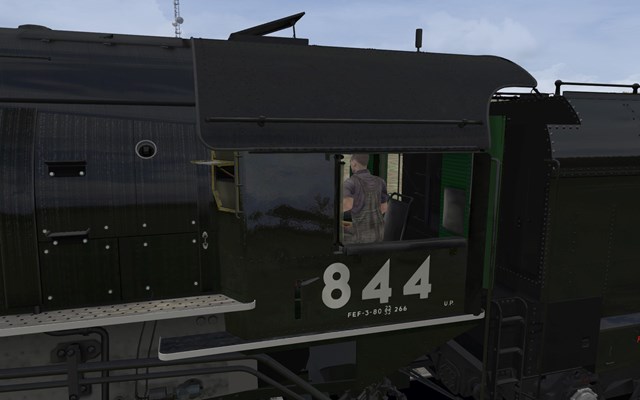
5.52 – Driving the SP Cab Forward
512 Driving the SP Cab Forward

One of the most remarkable engines in the USA was the Southern Pacific Cab Forwards. This oil fired engines has the cab on front of the boiler instead of the regular steam locomotives. This change in design gives the driver much more visibility because the boiler was actually behind the cab. In practice the engine in normal position was actually running backwards. The SP Cab Forwards DLC brings this amazing engine back to life within TS2015.
The cab forward design was widely used by the Southern Pacific Railroad, which developed it to deal with the peculiar problems of its routes. The 39 long tunnels and nearly 40 miles (64 km) of snow sheds of the Sierra Nevada Mountains could funnel dangerous exhaust fumes back into the crew compartment of a conventional locomotive.
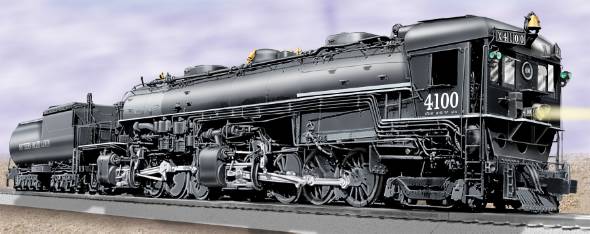
Now regular steam locomotives within TS2015 running through a tunnel will give suddenly the message Fatal Blow Back! and the scenario is over because of the lack of opening the blower and remains shovelling when passing through a tunnel. In practice this is dangerous.
During firing up you encounter a blow-back when opening up the fire door to fire while the blower can not be used due to the lack of pressure. Remember this photo during the firing up process mentioned in chapter ## without a blower:
After a number of crews nearly asphyxiated, the locomotive was run in reverse. This meant that the tender was leading the train, which introduced new problems. The tender blocked the view ahead and put crewmen on the wrong sides of the cab for seeing signals. The tenders were not designed to be pushed at the lead of the train, which limited speeds. Southern Pacific commissioned Baldwin Locomotive Works to build a prototype cab-forward locomotive, then ordered more units before the prototype had even arrived.
Even in Europe some railroad companies has experimental Cab Forward engines and one of the best know European Cab Forward engine is the German 05 003 with a “Hudson” wheel arrangement 4-6-4 There were also some experimental Cab Forward engines in Italy and Russia
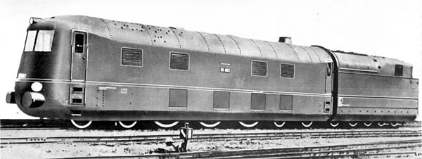
All of the cab-forwards were oil-burning locomotives, which meant there was little trouble involved putting the tender at what would normally be the front of the locomotive. The oil and water tanks were pressurized so that both would flow normally even on uphill grades. Visibility from the cab was superior, such that one crewman could survey both sides of the track without difficulty.
No other North American railroad ordered cab-forward locomotives, although some did like Western Pacific, has considered the Cab Forward. Built to deal with difficult terrain, the articulated locomotives became an easily recognizable symbol of the Southern Pacific. In total, 256 engines, in three different wheel arrangements, were eventually placed on SP’s roster. One example of the type, Southern Pacific 4294, is kept at the California State Railroad Museum in Sacramento, California. It is a 4-8-8-2 locomotive and is the only one to escape being scrapped. It was also SP’s last new steam locomotive, built in 1944.
Driving these giants will give some special experiences within TS2015. Some scenario’s does have the scripts the engine controls will not be accessible for a few seconds and gives the feeling you are running a run-away train. After a while you are able to gain control again.
The reason is quite simple. During the run down the slope you lose controls due to the weight in practice. However the speed is very limited you have no control over the entire train. Nothing is operational neither the brakes. So sitting in the driver’s seat you can NOT govern the engine which gives a strange effect.
The controls are not very much different as the standard DLC engines, but differently ordered. You have to be aware of some issues before you set off on a run or scenario. You have the most controls at your left hand, including the brake levers
The reverser and brakes are just left of the driver’s seat.
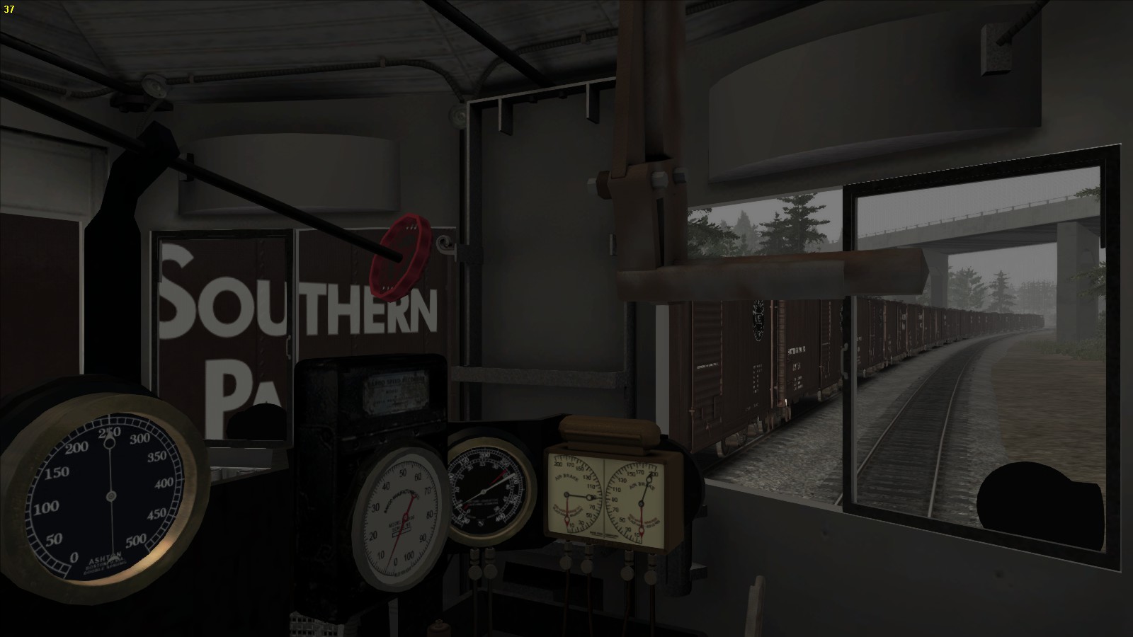
The gauges are all brought together, well organized and are readable in a blink of an eye. The design of the cab gives the driver and fireman an amazing feeling of vast freedom and good view on the track in front

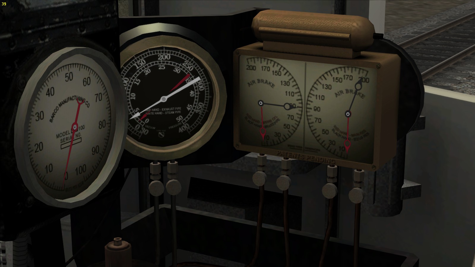
Mention the live injector which is situated at the left side of the fireman’s seat and the exhaust injector which exists of two valves at the valve board at the right hand of the fireman’s seat. Unfortunately only 3 of the 7 valves visible are operational. The valve directly next the oil regulator is the blower. The others are valves are static. The brass colored lever is the oil regulator and is operatonal by pressing [ R ] to increase and pressing [ Shift ] – [ R ] to decrease to oil flow.
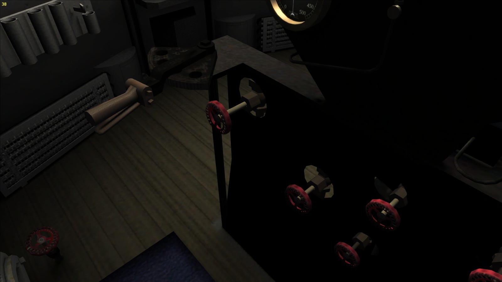
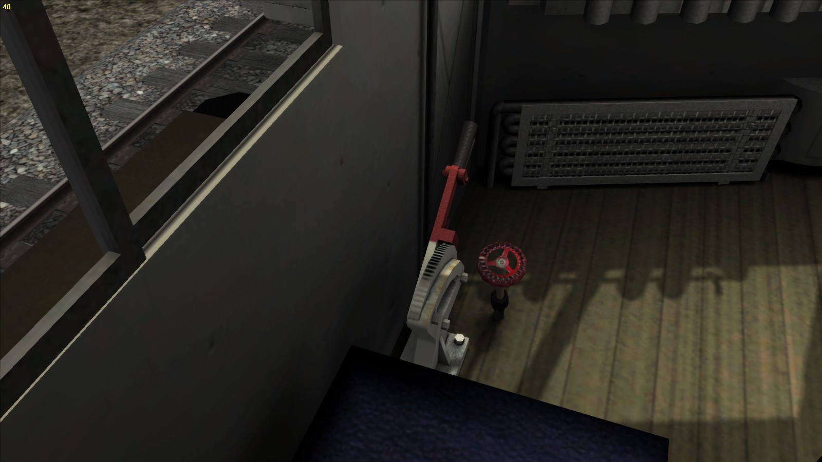
The cab is well organized and contains a lot of space. Under the wind screens two radiators are installed to keep the cab warm. This seems quite rare but the heat of the firebox now moves away from the crew and not towards them as it does in a common steam locomotive.
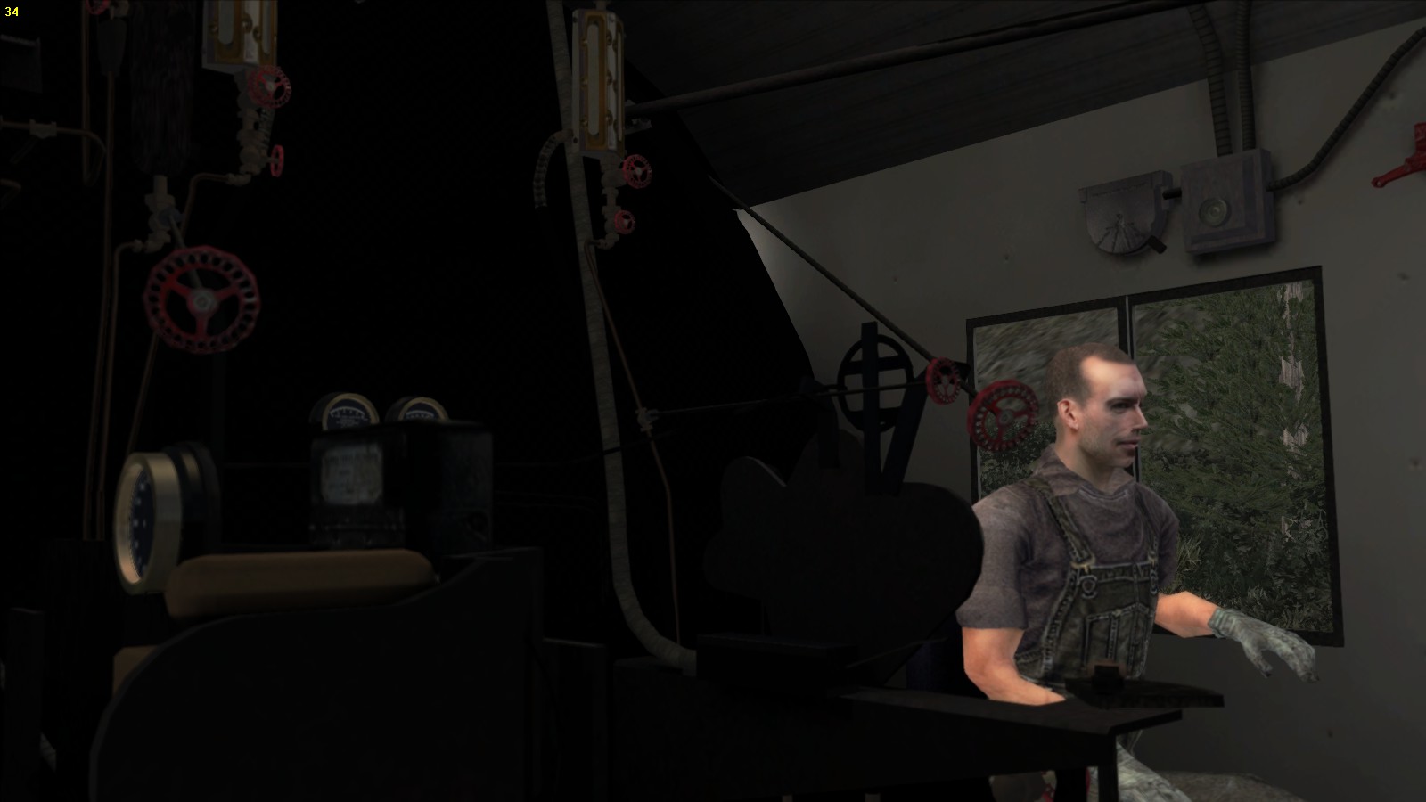
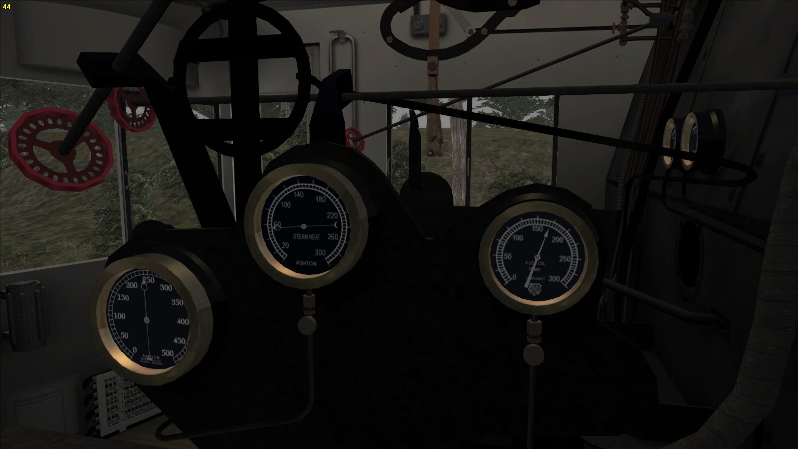
While the engine itself is very basic in operating in TS2015. The other levers and valves are static but it gives a plain sight of a real American cab.
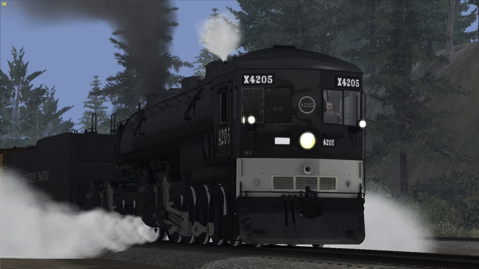

During stoking the oil is guided from the tender via a tube under the boiler, a broken oil pipe could cause oil leakage and oil is spoiled on the track and of course with slipp
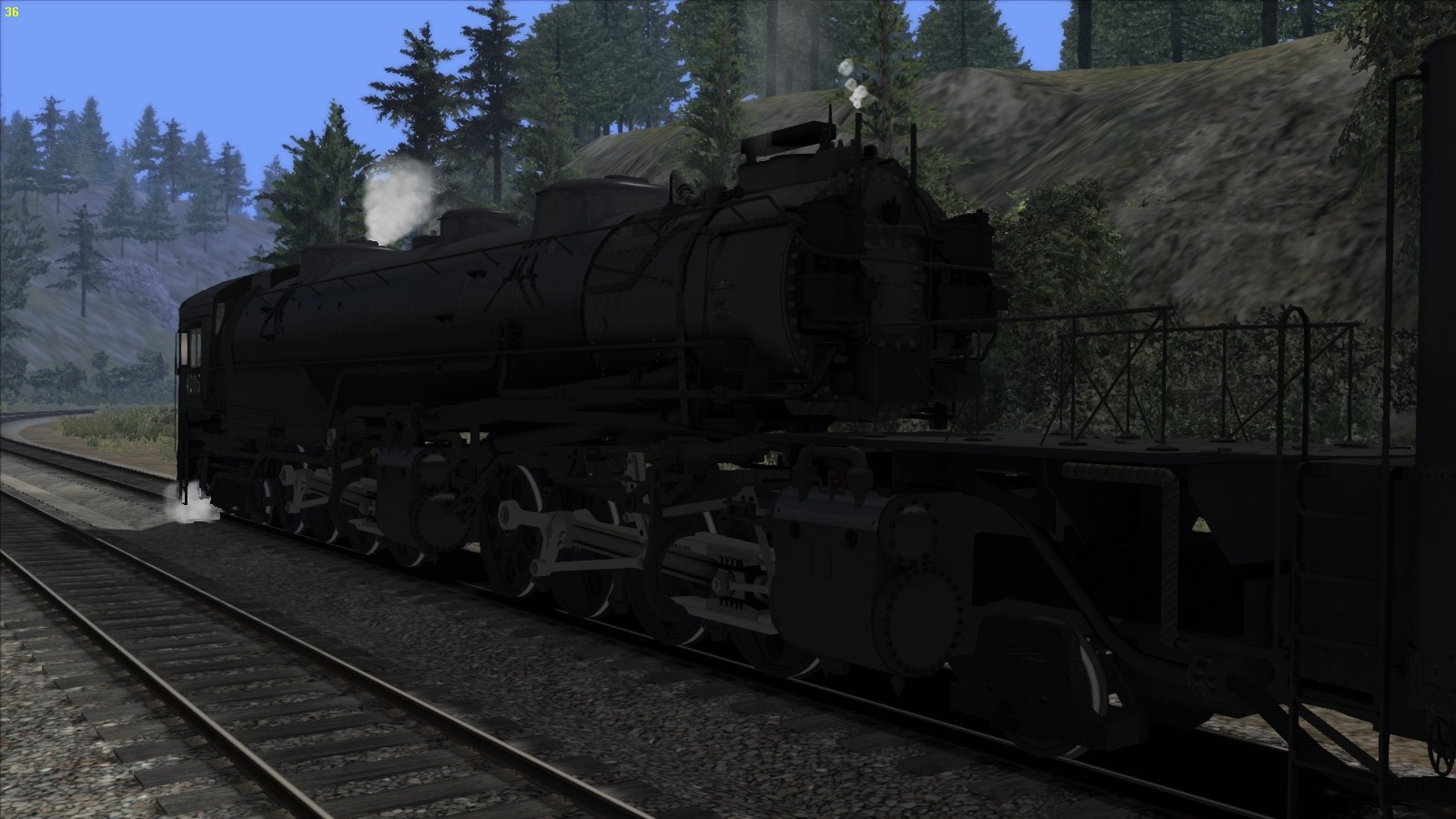
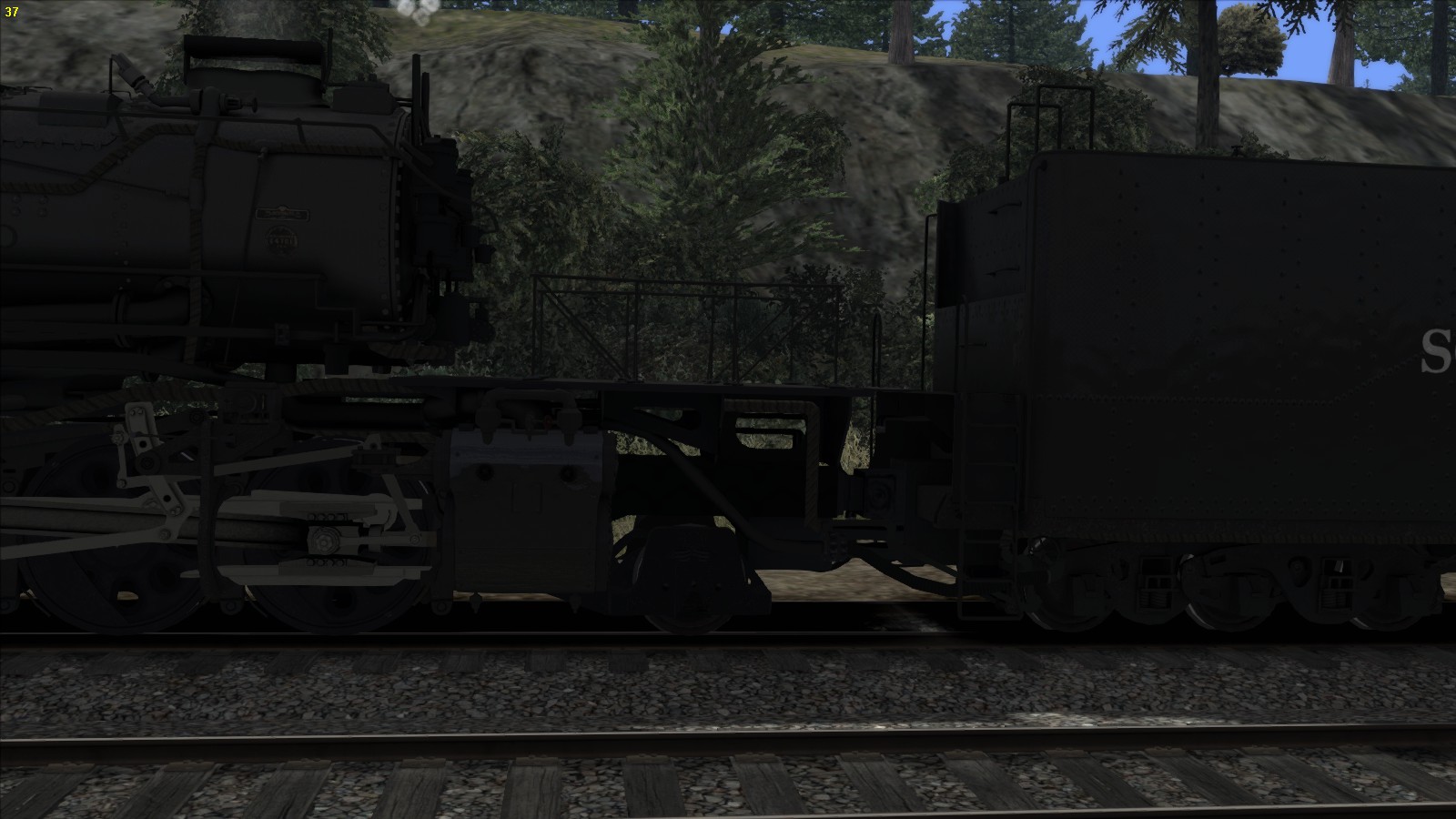
5.53 – The SP Cab Forward footplate
Mention the live injector which is situated at the left side of the fireman’s seat and the exhaust injector which exists of two valves at the valve board at the right hand of the fireman’s seat. Unfortunately only 3 of the 7 valves visible are operational. The valve directly next the oil regulator is the blower. The others are valves are static. The brass coloured lever is the oil regulator and is operatonal by pressing [ R ] to increase and pressing [ Shift ] – [ R ] to decrease to oil flow.
The cab is well organized and contains a lot of space. Under the wind screens two radiators are installed to keep the cab warm. This seems quite rare but the heat of the firebox now moves away from the crew and not towards them as it does in a common steam locomotive.
While the engine itself is very basic in operating in TS2015. The other levers and valves are static but it gives a plain sight of a real American cab.
During stoking the oil is guided from the tender via a tube under the boiler, a broken oil pipe could cause oil leakage and oil is spoiled on the track and of course with slippery results.
The DLC scenario’s are well worth to drive, however keep the speed low.
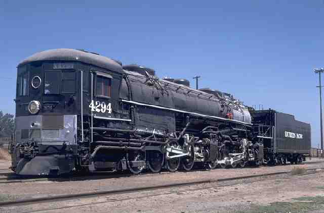
5.54*** – Driving the Consolidation
This chapter is in preparation
6.00 – Maintenance performing
Maintaining of engines is important to get the best performance out of an engine. When you drive the engine you are partly responsible for maintenance during stationary at depots. small workshops are direct accessible for drivers to perform small repairing and restorations. The workshop is also responsible for the engine as well where the engine is based.
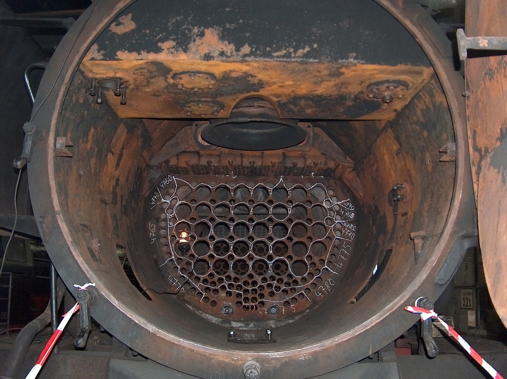
6.01 – Engine maintenance: The Boiler
A steam locomotive requires specific attention and technical knowledge. Regularly on pre-scheduled times the loco needs inspection and examining regarding all taken measurements to meet the highest standards to gain safe and high speed driving in the best economical and less expensive way. Throughout all the years the steam lcomotive was in service. Engineers always redesign and recalculates the best way to perform better, using cheaper materials and methods to make an engine cost effective. Though this chapter is not directly needed for TS2015 but reveals in a short overview what it takes to repair an engine. For a complete and enhanced technical overview, visit a workshop from a club or society otherwise try to make a holiday with a visit to RAW Meiningen in Germany.

The most important power source of a steam locomotive is the boiler. A boiler is continuously pressurized at about 220 PSI / 16 Bar. It is therefore rather important to inspect the boiler closely, and investigate on metal fatigue. The tremendous forces a boiler endures could result in an explosion if the boiler is not treated well. In chapter 3 a boiler explosion is mentioned.

Stainless steal is used here for the new boiler for the Tornado 60163 in RAW Meiningen
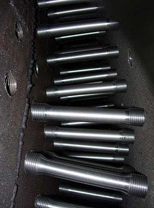
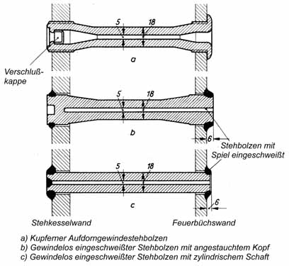
The stays of the boiler holds the inner surface of the fire box and outer surface of the boiler steady in place. The water and pressure is captured In between both surfaces. The diagram shows three different stays. The stays are all hollow to avoid total refracting on certain pressure changes.
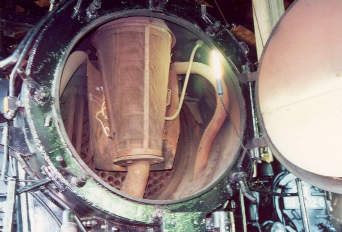
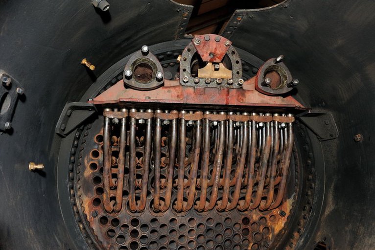
On top of the boiler the dome is present. The dome is to prevent water priming. The valve inside the dome is installed with the steam inlet upwards. in the valve that is regulated by the regulator contains a series of valves that opens up one after each other. The first valve has the smallest steam inlet and the last valve has the widest steam inlet.
These series of valves are operated one after each other. The reason why this is installed has to do with the amount of steam that suddenly is revealed into the steam pipe. The steam released into the pipe is saturated steam that now is led to the super heaters if installed.
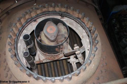
During a blow down not all sediment comes loose out of the boiler and some lime sediment will still settle in the bottom of the boiler. At strategically points the boiler contains special oval shaped hatched that can be removed when de boiler is depressurized and dewatered.
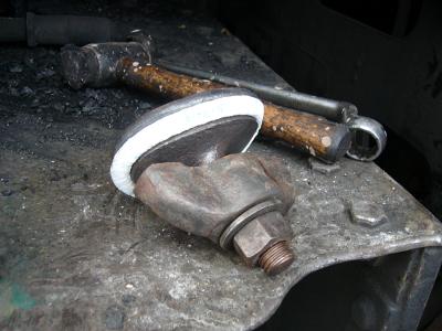
The wash-out plugs removed. Mention the oval shape model the plug has. These plugs need to be unplugged from inside out. The bolt that is welded on top of the plug contains a nuts and a bore hole. Through the bore hole a string is placed that attaches the hand of the employee to avoid the plug to drop down in between the tubes and pipes inside the boiler.
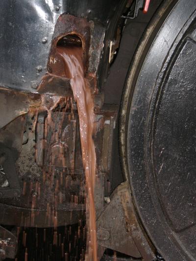
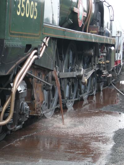
The wash-out takes about 1 hour to take place completely depending the size of the boiler. After unplugging the wash-out plugs from the boiler, water now is sprayed into the boiler at high pressure by a spray lance will flush all the lime scaling from the bottom, tubes and pipes
The sediment feels like mud (also called “slush”) and contain clogs of lime, some hardened out to a stone like shaped bricks that scratches the hands of the worker busy at the wash-out. The wash-out of the boiler is finished when the water that comes out of the wash-out gap is crystal clear.
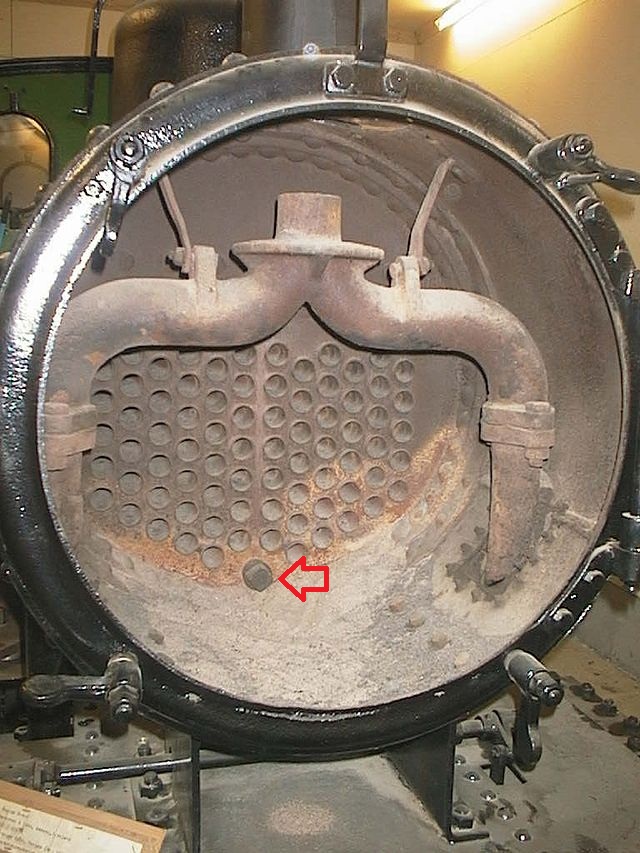

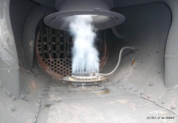
When the smoke door should be closed here.
A vacuum is produced due to the working of the blower pulling all air through the fire grate, boiler pipes and tubes through the chimney together with the hot gasses and coal sparks.
The boiler studs supports the boiler that carries the weight of the boiler onto the rigid frame. This point is fixed to the frame the other side of the boiler is carried by slider bars the carries the weight of the boiler but the boiler is able to move parallel to the frame by these slider bearers. The slider bearers are attached at the side of the fire box. These sliders are mounted to the frame.
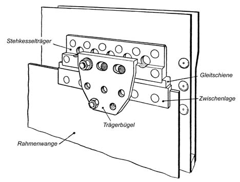
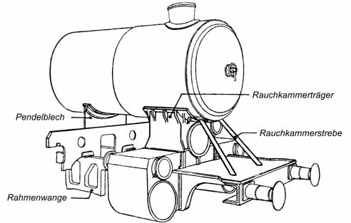
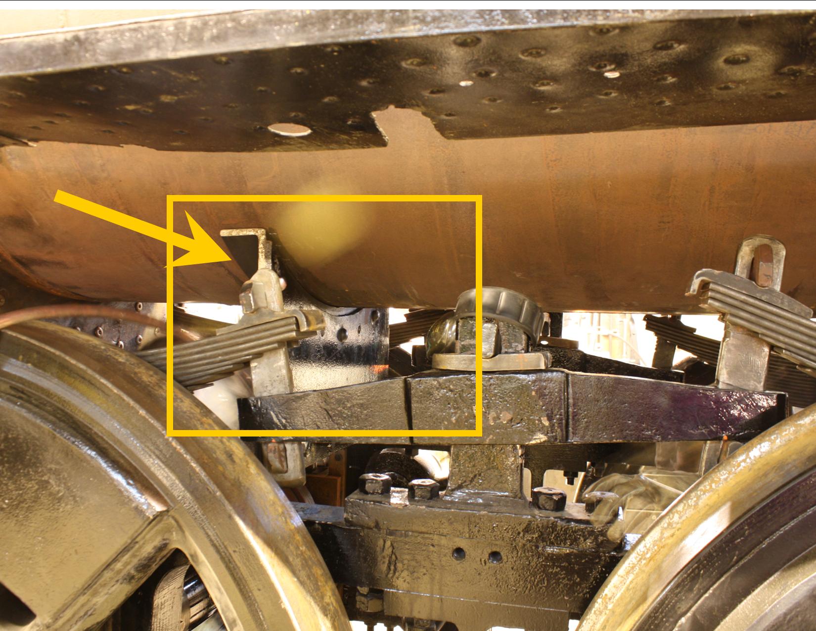
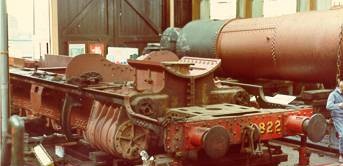

The boiler now rest on top of the frame that is supported by these studs and slider bearers.
The weight of the boiler is divided over the different support bearers.
6.02 – Engine maintainance: Frame and Wheels
602 Engine maintenance: Frame and Wheels
To continue with the maintenance chapter we now going to take a closer look to some of the necessary items directly related to the Inspection of the frame is even important to support the engine itself.
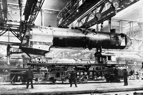
The frame contains the driving wheels fitted in roller bearings that are mounted in the frame using a set of rigid springs and sliders. The frame bears the forces to haul the train in either both direction. but is absorbed on the buffers and couplers. Larger engines contains pilot trucks into guide the frame that bears the boiler and cabin that is installed on top of the frame. The frame on its own is the most important piece of metal that keeps the most parts of the engine together
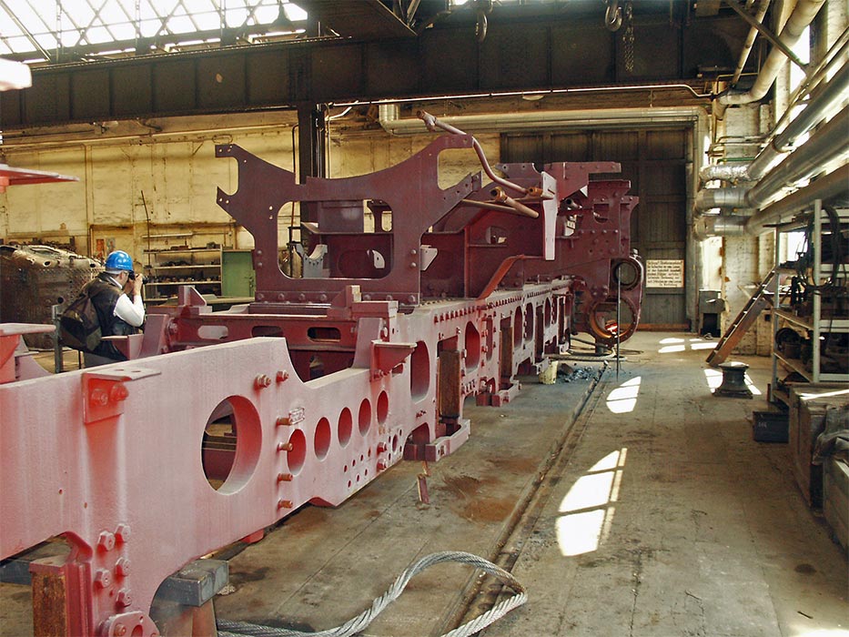
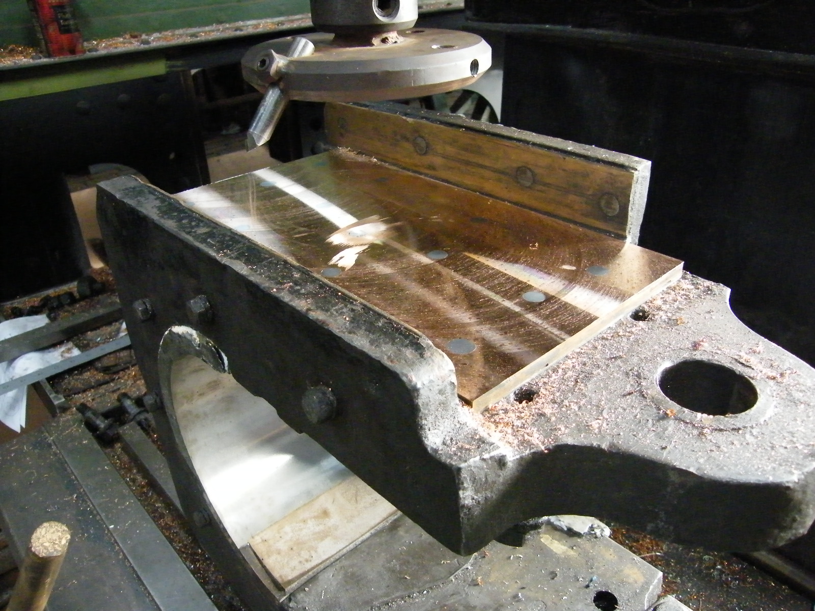
After installing the wheel bearers in the frame. a set op springs will be installed and is able to equalize the mass weight pressure and is able to adjust the mass weight at every axle seperately.
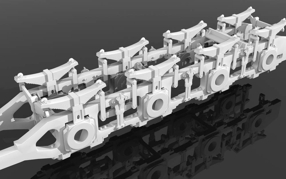
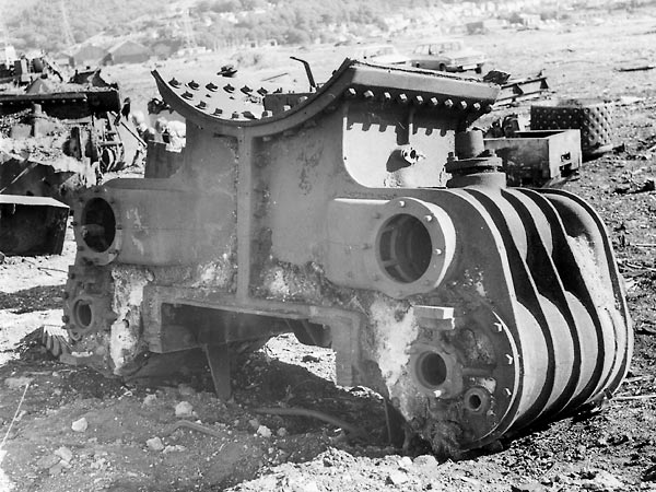

Two cylinder blocks together. The left one is an original cylinder block while the right one is a cylinder block for a live steam engine. ready for further preparation and casting.
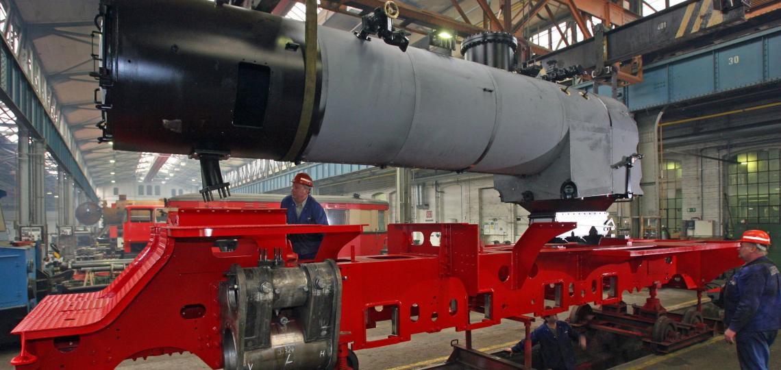
Before the wheel sets are installed the boiler needs to be installed first. After the installation of the boiler on top of the frame, the wheel bearers will get installed. Then the whole frame is lifted up again to make it possible to install the wheel sets from underneath. After lifting up the boiler and frame, the wheel sets are rolled in place manually.
The frame and boiler are now lowering down over the axles until the complete frame is resting in the wheel bearers. This is one of the main fabrication processes of the steam locomotive and is also a part of the maintenance process as well. After this process the engine is ready to further installation of additional equipment.
The cylinders are the “engine” of the whole train. the cylinder blocks has to be installed tight at the cylinder blocks
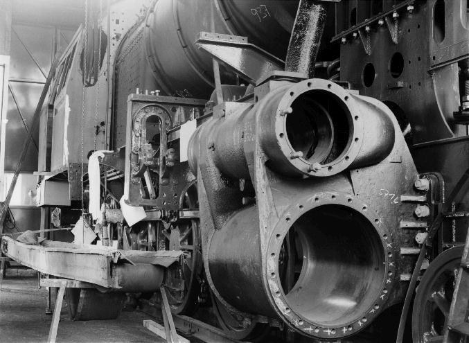
The forces on a working cylinder blocks are tremendous the riggid forces are interpreted into the strength of the frame. The motional forces are guided via the pistons and piston taps causing the train to roll and move.
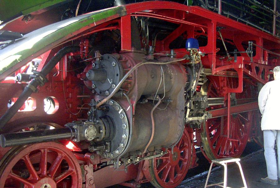
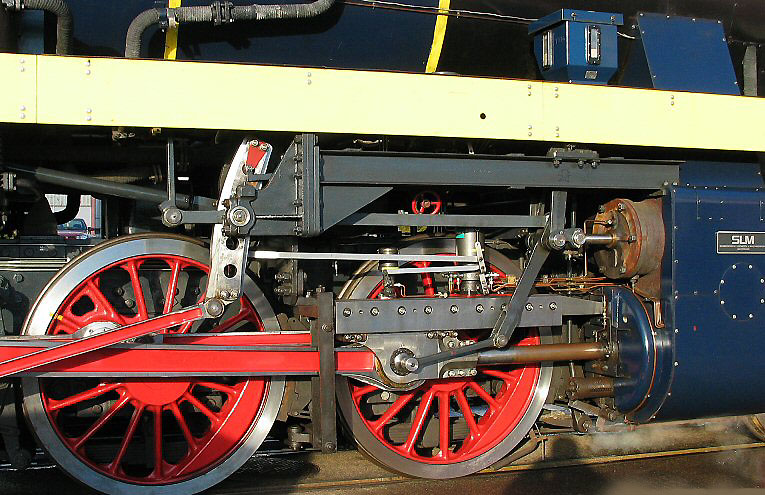
The wheel sets are mounted together. and the wheel rims are set up. After this installation the wheel sets will be put in place
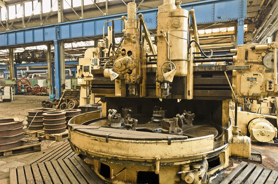
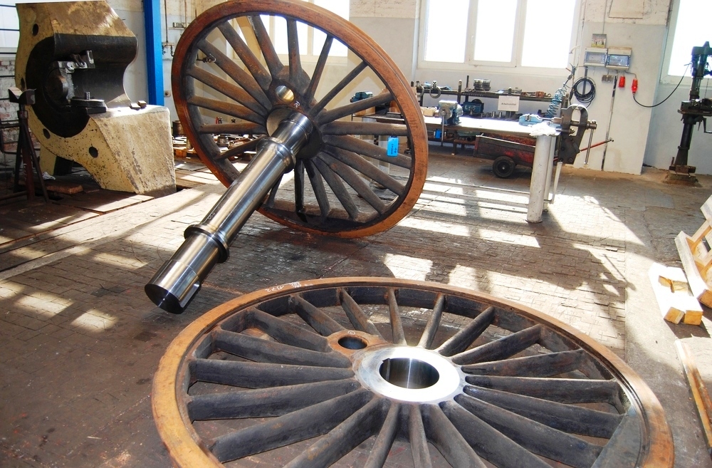
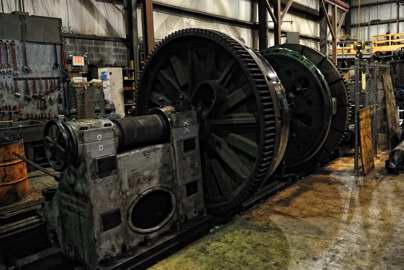
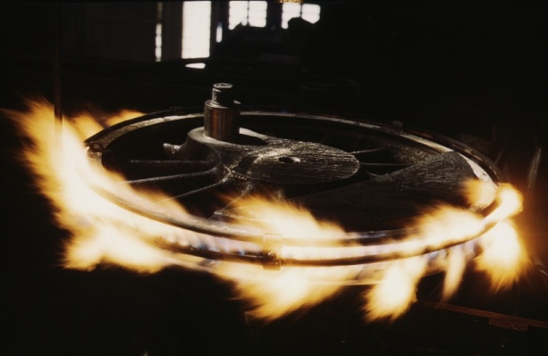

Wheel rims are separate steal wheel “tyres” that are mounted around the wheel itself. The rim can be installed after heating up. The heat the wheel rim causes the rim to expand enlarging the circle diameter that now easily fits the wheel itself. After installing the wheel rim cools down and will shrimp tightly the wheel itself rigid and tight.
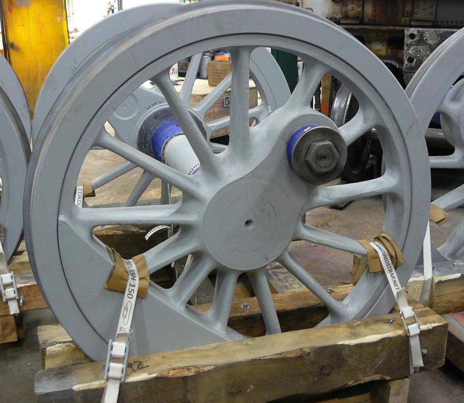
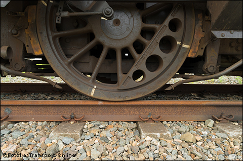
After attaching of the wheel rim at the wheel itself the wheel becomes white markers which are needed to check out in a simple way if the wheel rim did not move. Prior to every run the train driver and shunter man checks this markers. When a marker is out of position the wheel rim has slipped over the wheel and could cause major problems. If a white marker is noticed “broken” the engine, coach or wagon will be lifted out of service immediately and will be send for repairing as soon as possible.
The diagrams shows exactly how the rim is fitted on the wheel itself. Though the explanation is in German Language, the process of installing a wheel rim is quite simple, the installation required heavy equipment to perform a replacement of the wheel with a new rim.
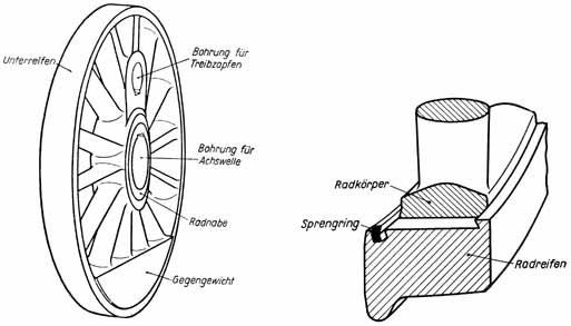
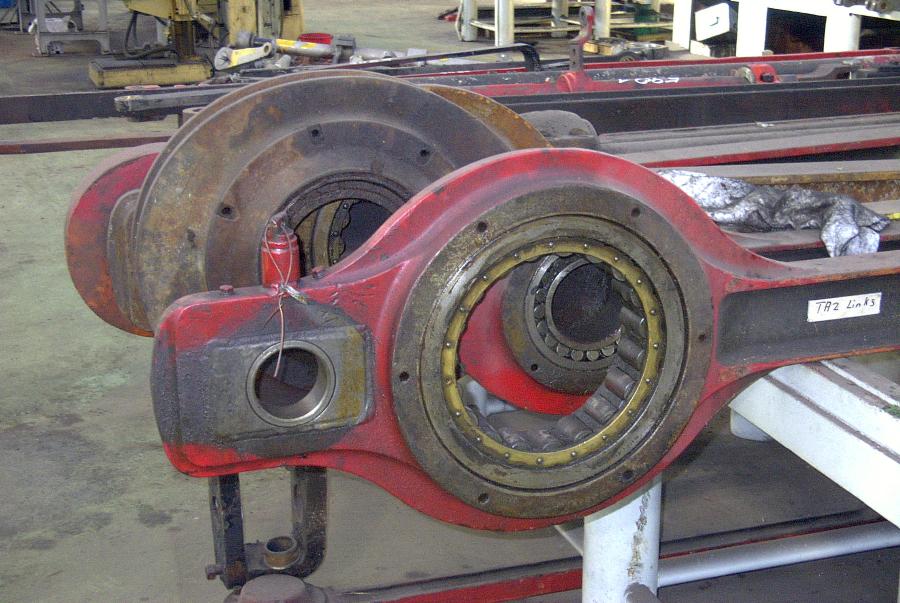
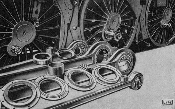
The Frame, Driving wheel and Cylinder blocks are now ready, what needs to be done yet is installing of bogies, pilot trucks and equipment.
6.03 – The tender and equipment
Large steam locomotives requires a vast amount of supplies like coal, oil and water.
Though it can not be fittet at the loco itself because of the vast amounts. In the early days it was already obvious to have vast amounts seperately in order to maintain timetable, speed and endurance. A special suited wagon was needed to provide the engine the supplies needed. The tender is made out of different “chaimbers” that are in use as storeage tanks. in these chamibers water and coal are present.
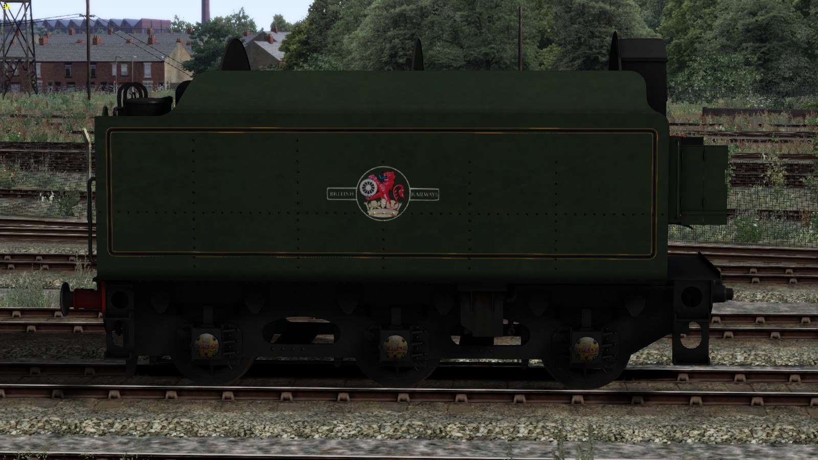
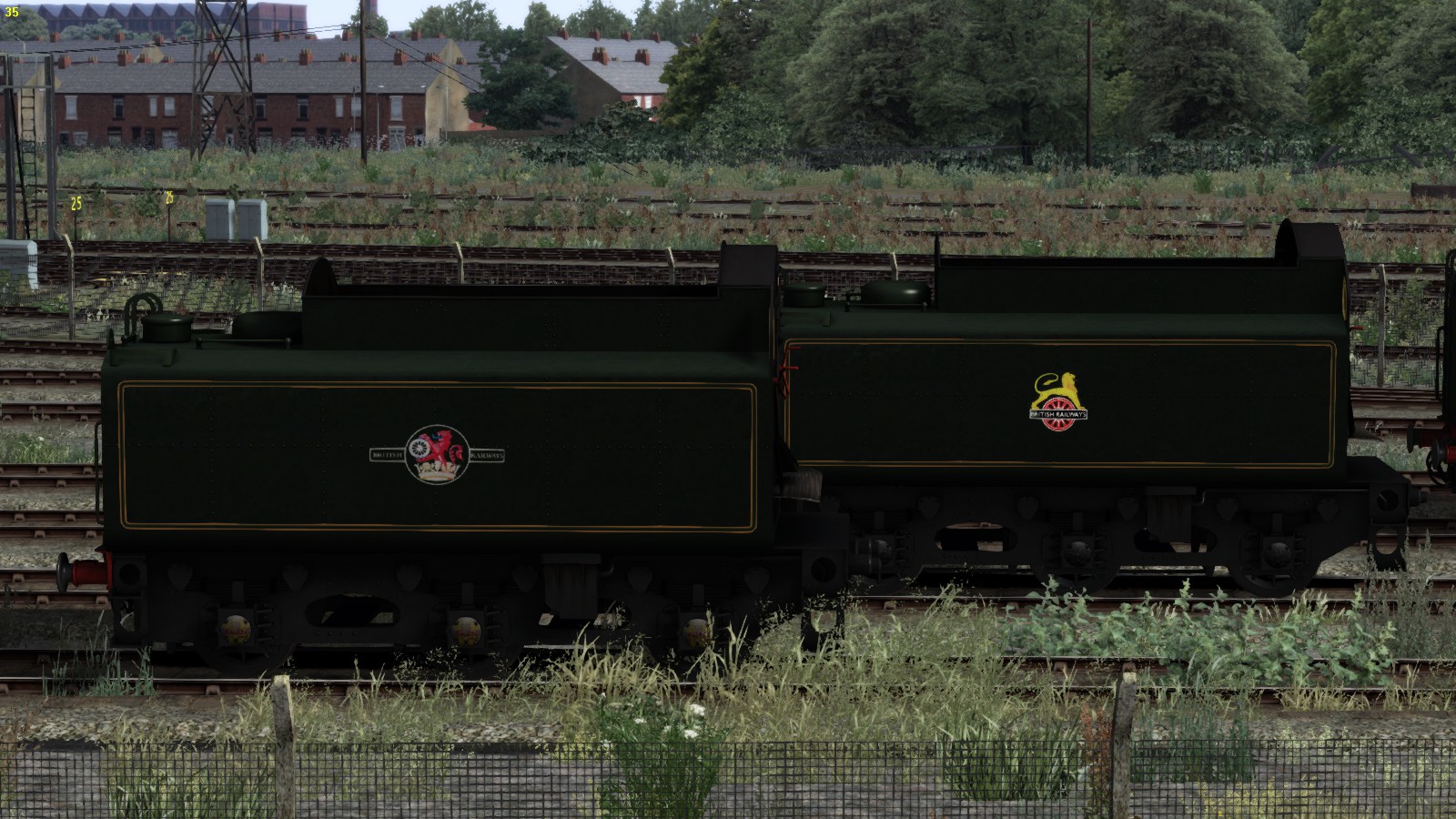
Some tenders in advanced mode within TS2015 has some features installed like opinging the coal door and an indicator to show the water level. However the water indicator is not always clearly visable due to the lack of light.
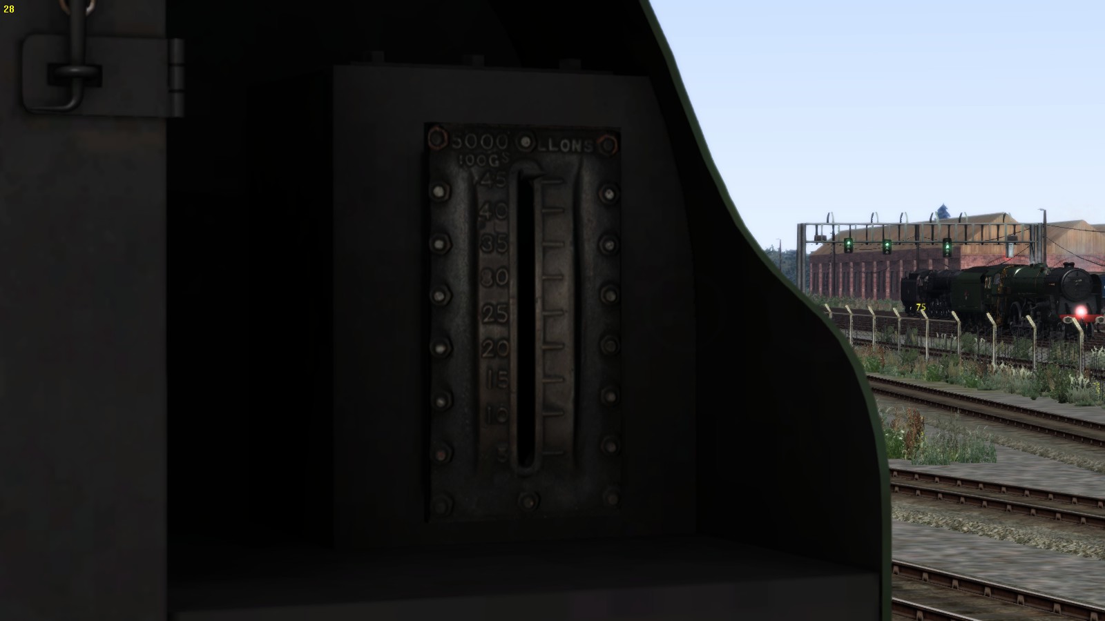
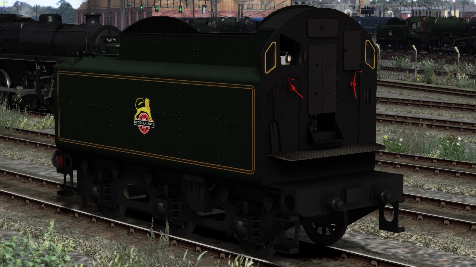
Now when you are running a scenario, mention the water level in the tender itself, accessing theis information takes place by pressing [ F5 ] 2 times and read the information that becomes visable in the screen slight left above.
Most early tender has no extra or extended enlargements to contain vast amounts of water and coal or oil. This resulted in regular visitations of the depot to top up supplies and needed to stop more often to top up the water.
Later model tender could contain even more coal due to the improvement of the coal storage
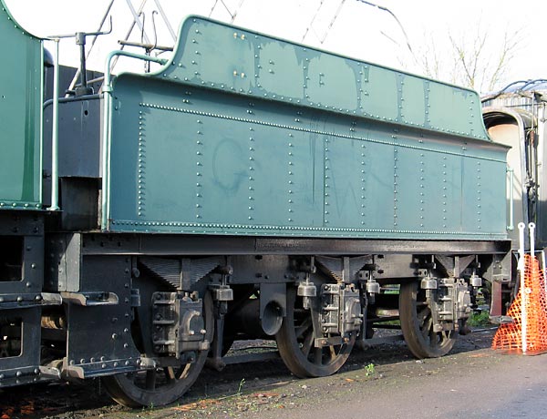
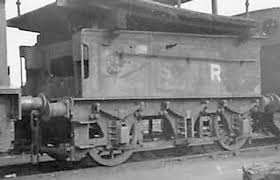
Old tender often became a second life as storage/supplier wagon at workshops and sheds.
To reduce the topping up of supplies became the reason for engineers to reconstruct tender to improve the mass content of supplies. Tender became heavies as they became larger and bigger.
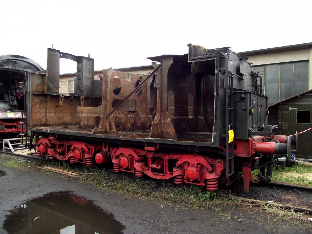
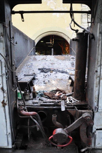
Clearly visable is the “slope” that contains the coal. The slope gradient causes the coal to rumble down the slope to the fireman when driving.
This “moves” the coal towards the fireman. Mention the German style hand brake which is set.
The tender is mainly suited to transport mass weights tat is needed for direct support and supply the engine while driving. The tender does not only carry the supplies, but eiter additional supplies and tools for stoking and maintainance are also present at the tender.
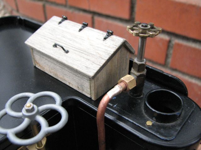
At the rear of the tender a tender cabinet is present that often contains grease and oil to lubricate the engine when stationary. These cabinets often contains heavy equipment like large strappers and hydraulic jacks.

The tender of a German Class Br38 Ten-Wheeler is even equiped with an air tank that is installed right on top of the rear cabinet at the tender.
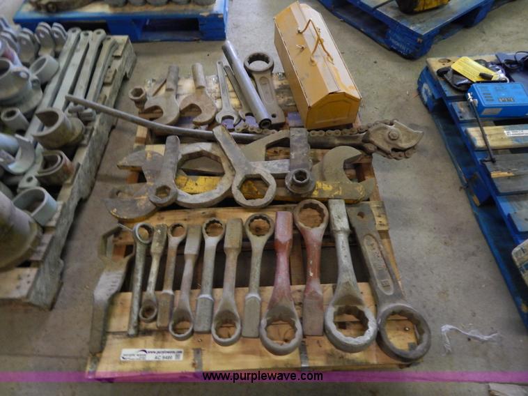

This small toolbox is an excellent example to carry along when inspecting the engine.
An overview of heavy equipment and tools. Not all equipment you see here is directly part of the standard tools of a steam locomotive, but it is part of the workshop.
The primairy tools that are in use by the engine crew is always directly accesable.
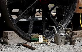
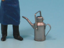
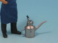
Other tool cabinets are mostly present in the tender at the front side and is directly accesable during the run. Watch the photo’s below and mention the colored rectangles that relates to the list underneath the photo’s which declares the usage of the tender cabinets clearly.
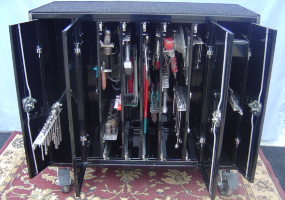
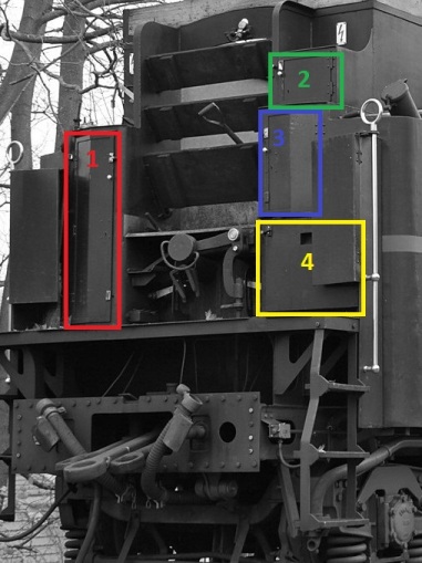
Refferal list according the colored rectangulars of the photo above.
- (Red) Tool cabinet that contains a rack of tools.
- (Green) Cabinet for the storage of old shreds and back-up light bulbs and water scoop glasses.
- (Blue) Crerw cabinet to store personal belongings like clothes, cabs, food and drink.
- (Yellow) Cabinet to store oil cans and a small toolbox.
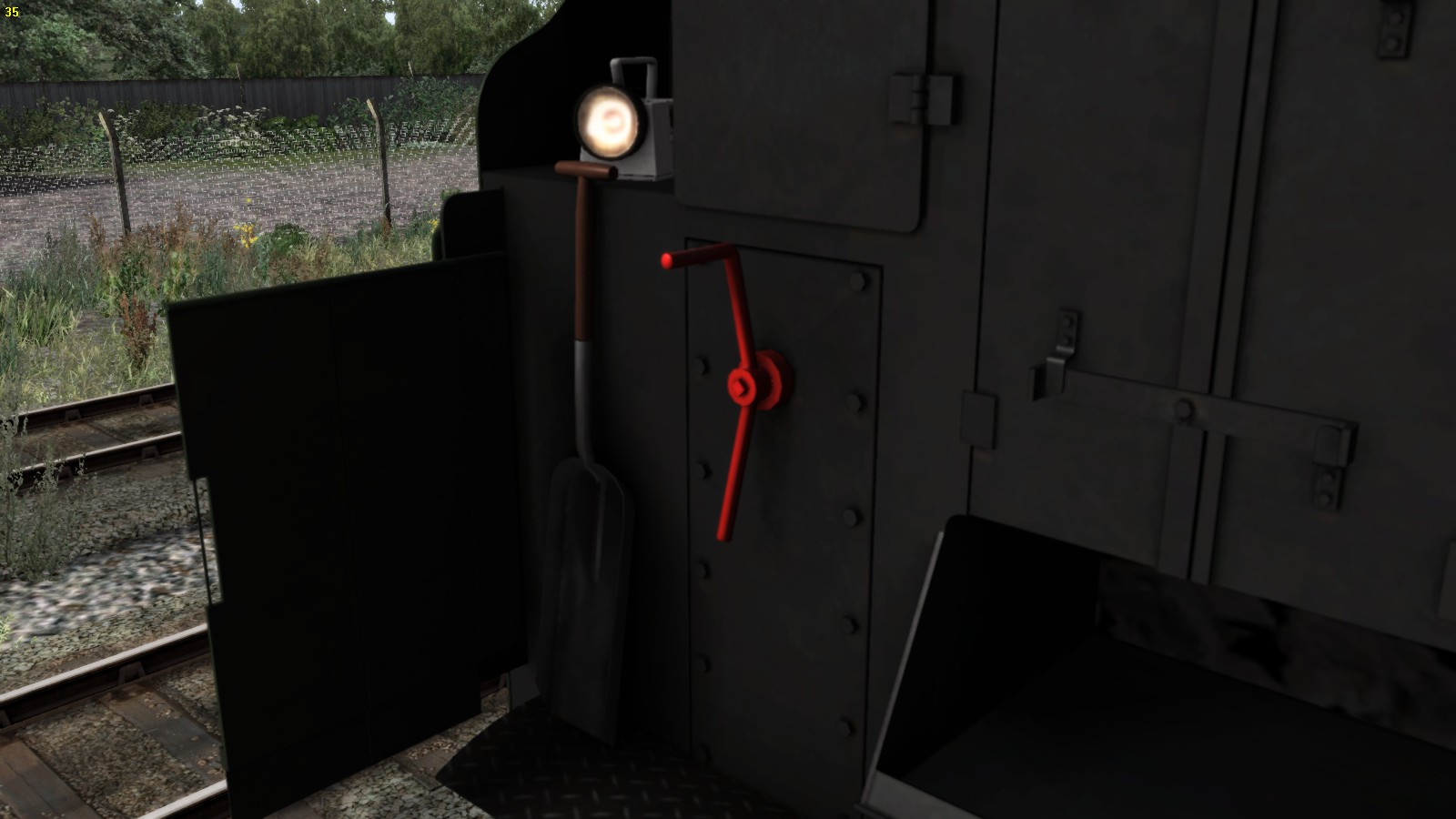
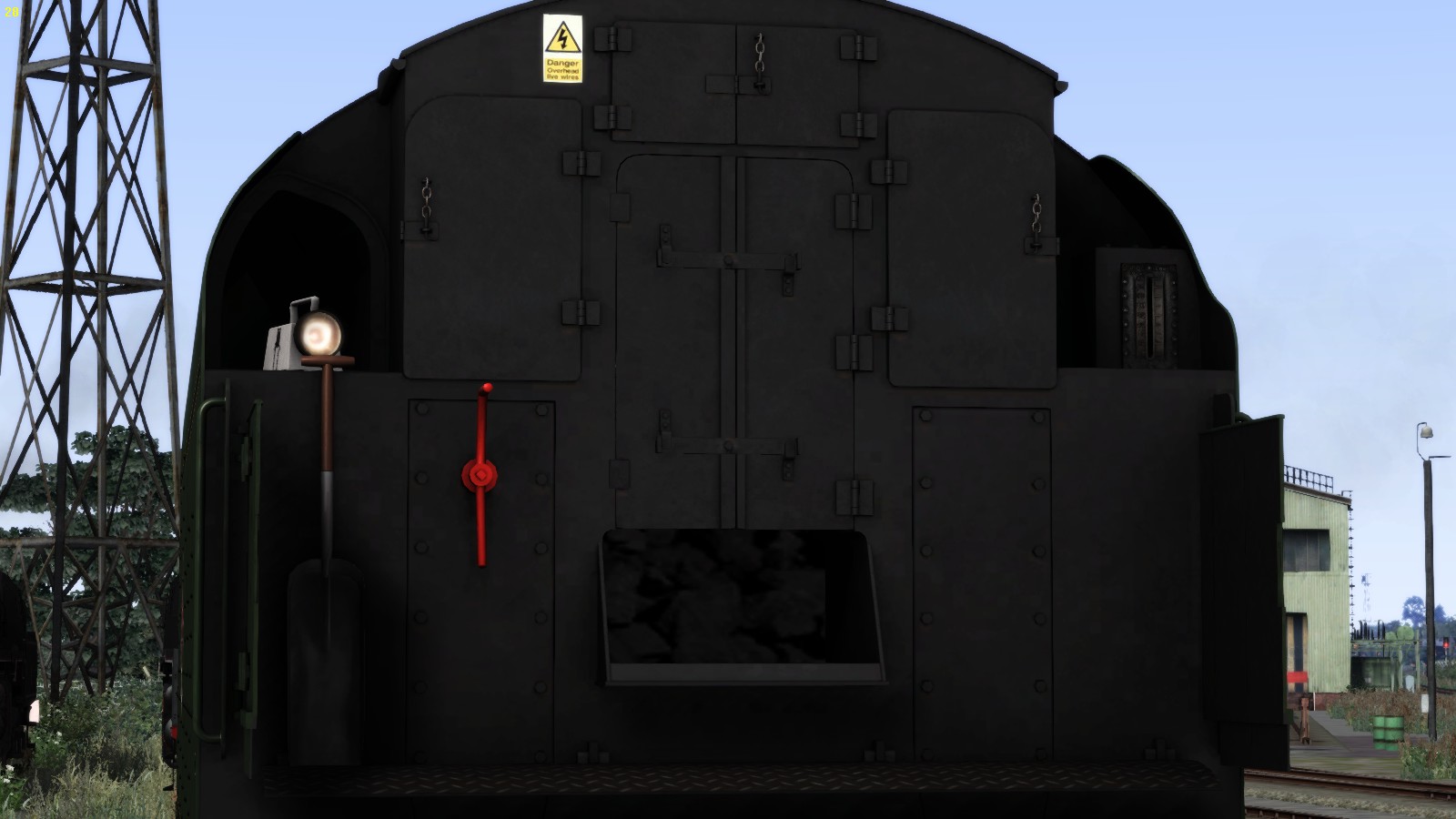
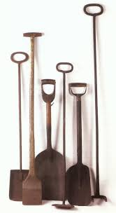

The red arow displays the storage tube to store the stoking tools and equipment.
Stoking tools and equipment are often stored in a storage tube that is installed directly underneath the coal door and contains large tools for direct access from out of the storage tube into the firebox. After the use of these tools fireman and driver pay attention to these tools due to the high temperature the tools contains after usage. protective gloves are highly advisable.
6.04 – The tender and equipment – part 2
The post steam era
Since the disappearances of the steam depots after the steam era was ceased the problem came how to manage and provide the necessary supplies on a steam special. The solution was found in the adding of an extra tender to the steam locomotive.
Extra tenders provides the engine the back-up supplies in case when the 1st tender becomes empty.
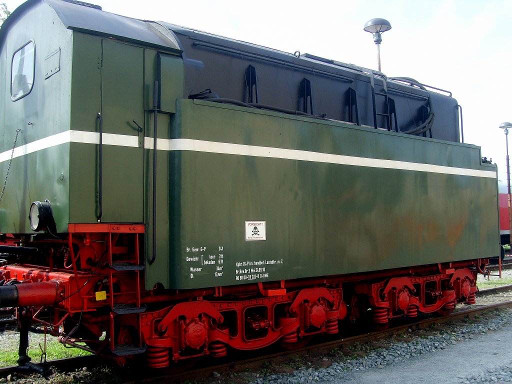

Union Pacifics Challenger additional tenders to cover the vast amount of supply due to the consuming rate the Challenger has.
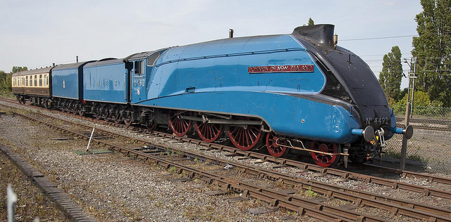
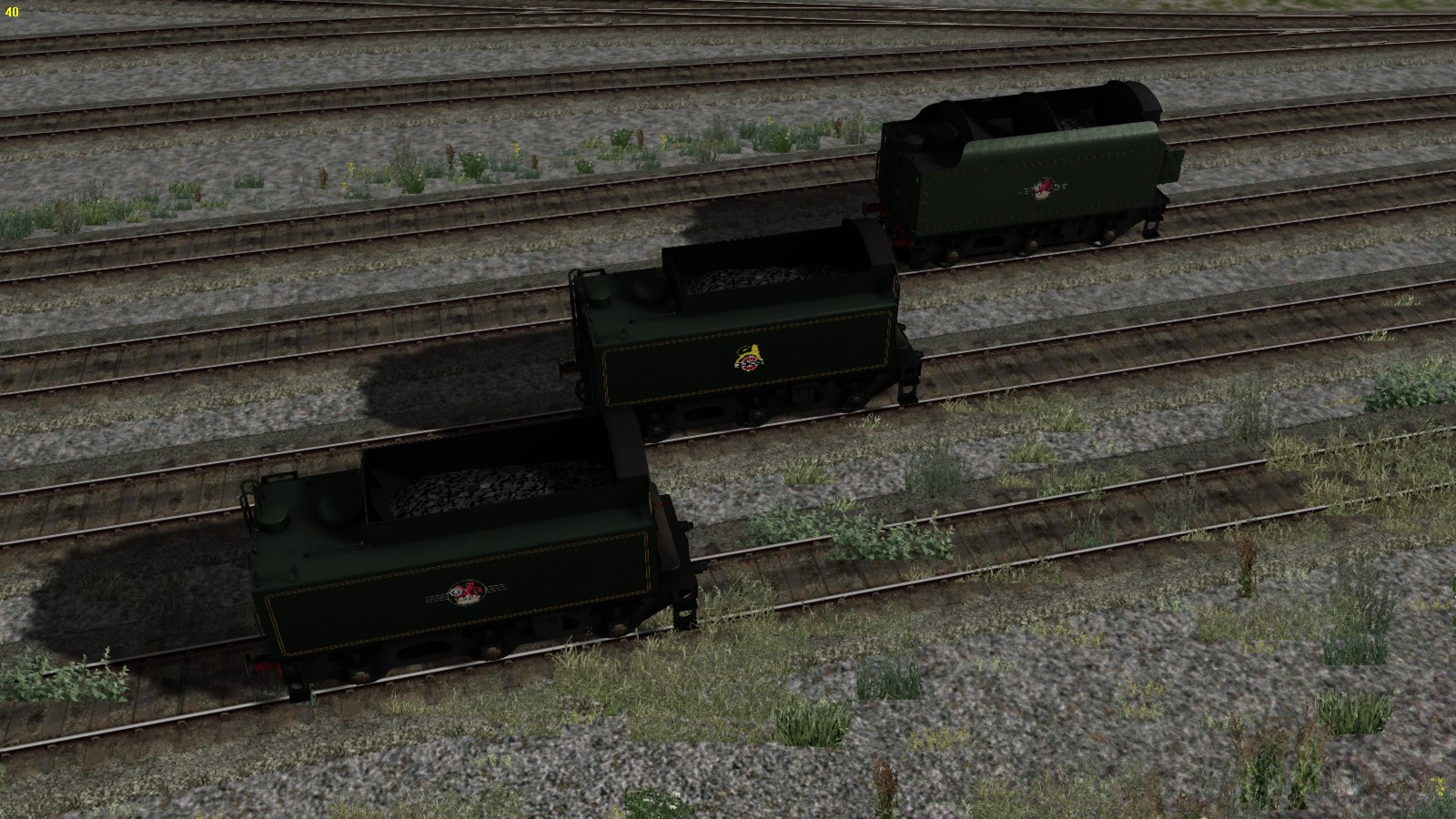
7.00 – Practical issues
Practical issues like getting prepared for a job and career as train driver are mentioned here.
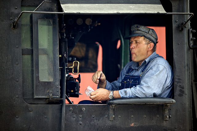

7.01 – Getting a career and job as train driver – part 1
701 Getting a career and job as train driver?
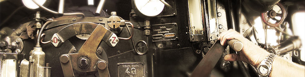
This article however is not directly dedicated to steam trains only but it concerns all trains globally. Becoming an engine-driver is not just your passion of trains, it is a mass transportation tool.
In one single train you, can transport tons of materials, freight, hugh amounts of passengers.
The whole infrastructure is specially equipped and designed to run trains. Your responsibility is hugh. When you are running passenger trains, the life of many passengers on board of your train are in your hands. A simple mistake can lead to many casualties.
TS2015 is trying to copy the reality on your monitor. A reality you can get common with. TS2015 gives you the feeling of driving a real train. Though it is still virtual, but good enough to get the full understanding of the basic knowledge of modern trains like: TGV, Eurostar, Class 395, Baureihe 101, ICE 3, Acela, Shinkansen, Koploper, Sprinter, Taurus, or whatever name a type of train is given.
To become a real engine-driver. Start to test yourself with speed-test, cognitive tests, vigilance tests, concentration tests and human resources interviews in order to fit and meet the requirements to become a real engine driver.
However it is always good to examine yourself on these issues one and a while. This will help you in other situations as well. Many professions requires HR exams. Particularly when safety measurements are potential in vain endangering humans, social environments, economical purposes and industrial areas.

At the right side you see an example of an colour blindness test. The coloured dots in green shows a number to read. This will be done in different colour grades and levels and different sizes.
The Red / green difference is the most important one because the small colour frequency of the red colour is rather the same as the green one. When your eyes has the lack of cones in your eye to pick up the right colour frequency, you will not able to see the difference in that frequency between red and green.
When you are about to be examined at the HR institute, the thrill will feed your brain and adrenaline will set off in your blood stream. This results in unexpected behaviour when you are on the examination period.
Though HR investigators knows all to well how to deal and handle with the situation.
They will always try to calm you down, and bringing you in a comfortable position.
Then they will start all over again, but on a next occasion, you will probably fail the examination.
It is that important to keep up with these tests and you are better prepared. Adrenaline is rushing less through you body. You know the questions globally. If you know the oncoming PC tests globally, you are ready to go for it.

To keep you focussed on the very hard facts, here is one question HR will ask you;
“What will you do when someone commits suicide and jumps on the track in front of your train when you are on full speed?”
Yes I know, this is a though one.
Here is what you do: KEEP CALM, apply the brakes, contact the CTC immediately, next; contact the chief of the train. Do not get out of the train to watch! Inform the passengers about a failure and needs to be fixed. Do NOT mention the real issue to passengers in this case. You have mentioned the chief of the train. He will take care for the passengers and knows what to do and what to say.
Try to get up with mathematics. Try to get up and boost your knowledge about technical and mechanical aspects as well. Bring yourself in line with all basic knowledge available online.
Test yourself regularly in order to keep up logical thinking. Trains is not just a hobby,
it is an important way of mass transportation and the economy depends on it.
Human resources and Group Bourdon test
One of the most famous test is the “Group Bourdon” tests GBT and SCAAT which is widely in use to test the cognitive vigilance of drivers and is repeat after a certain period (depending the requirements of the Safety regulations and Law which are different for each country).
The other test (SCAAT) is in use for BR and is to remind symbols and find that particular symbol in a line of other symbols. Tick it and move to the next one, and all as fast as possible without any mistake.
Except the speed test which requires a special keyboard, you can do and perform most tests online. It is always advisable to measure yourself as well prior to the use of TS2015. Though TS2015 is a simulation and to play a long run completely, never forget you are really perform in real-time a complete run without any pause or break. Achieving this goal will put you ready for the real thing.
Another hugh test is the interview on paper, the PC interview and the personal interview with an HR interviewer. All these examinations will reveal your skills and to be evaluated by the railroad company.
The Safety board tests, HR tests and medical examinations are restricted by Law. When you are on interview at an HR office expect strange questions in order to test your attitude and behaviour.
The same question will be asked in different ways checking you give the same answers over and over again. It is better to get yourself comfortable with it to avoid any surprise.
For steam societies and steam clubs running on the main line the same restrictions are being taken for fireman’s as well. The driver is normally a regular engine-driver at a countries national railway company with a license to drive steam trains as well. Drivers with a steam license driving at heritage and private railways are not always allowed to drive at the mainline. For these driver also the same rules and restriction are applied and is governed by Law.
7.02 – Getting a career and job as train driver – part 2
When a club owns a heritage or private line, the law is still in execution and valid for the hobby engine-driver as well. Even clubs running on Live Steam engines like 10,1/4 inch, 7,1/4 inch, 5 inch and 3,5 inch are dealing with the same issues of safety. Even on that miniature railway, safety always comes first. A 7,1/4 inch Black 5 for example is still a real working engine with a boiler pressurized by steam. Dealing with exact the same issues as the original example, these engines are still a potential danger if the driver does not know how to drive and maintain fire, water level and pressure and how take action is case of a situation occurs. These trains are still hauling passengers though for fun.
Doing the job when steam was still the major traction was slightly a different story.
In the next YouTube film here shows you how is was done after somebody became a railroad man. Mention for now. The films shows you what to do to get on a steam engine on a club or society.
Are you ready to do the job ?
7.03 – Examinations, approvals and tests
Before you set of as a professional driver you need to do tests and approvals to perform your job as a driver. This is always a important case. To drive properly you have to do these tests. Though it is not required for TS2015 it is still a very good issue to have to be examined as well.
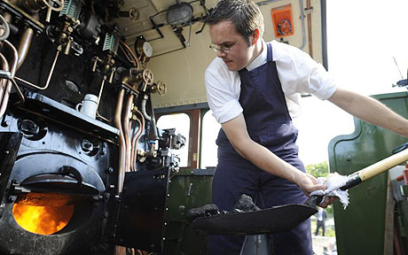
Though the guide is primarily mentioned to get the best out if driving a steam locomotive in the most proper way based on experiences and knowledge. The guide provides also a lot of side information that is usable for driving with electric and diesel traction as well. However it will also help you with your hobby how to get the best out of this magnificent rail hobby and even to get a job as train driver, you will have the best information available here in this guide.
These videos contains non-steam related videos about the daily aspects of train driving today.

____________________________________________________________________________
- Safety precautions and measurements along the track.
- Railroad naming and phrasing of railroad
- Chemicals
- Signalling aspects along the track.
- Naming the parts of a steam locomotive.
- The working of steam powered devices
- How to start a steam locomotive.
- The proper and precise sequence how to drive a steam locomotive commonly.
- Driving behaviours
- Lamp- and head codes.
- How to act on special occasions while driving with steam.
- Weather conditions.
- Lubricating.
- Water
- Coal
- Heavy Oil
- Steam locomotive maintenance by driver and fireman.
- Steam locomotive maintenance at the workshop.
- Common train driving.
- The brake system
- The onboard train protection systems.
- Avoiding accidents.
- Driving an Express Train
- Driving Local services
- Driving Parcel trains
- Driving Freight Trains
- Driving Track maintenance trains
- Shunting
- Banking
- Driving Double Headers
- The precise method of firing and stoking with coal.
- The precise method of firing and stoking with oil.
____________________________________________________________________________
The practice hall of GM Rail for education concerning points and signalling knowledge
____________________________________________________________________________
7.11 – Safe train spotting – part 1
Within TS2015 you have the option to program AI traffic and take position aside the track making beautiful screenshots. Right from the lazy chair you create the most astonishing images op passing trains you programmed. To create screenshots, you just press [ F12 ] and you find the fresh image in your screenshot map. Note the link to your map is rather difficult to find, but once you have the map opened, click and drag the map symbol from the address bar in explorer onto the desktop.
Once and a while there are steam specials. in order to get the best pictures of the passing steam locomotive, the chaser always tries to find the best spot along the track, no matter what it cost and chasers are completely unaware of the danger when filming or photographing the passing train. On preserved railway associations it is possible to make a photo session with a faked departure and an faked passing. The driver opens the regulator and reverser together with the brakes slightly applied to create a steamy environment with hugh working exhaust.
To get this pictures you have to choose a fixed point along the track, set your equipment and wait for the right moment of passing the desired train you waited for. But are you really aware about the danger and rules? It is commonly forbidden by law for everybody to take position in the ballast, the walk path and within the borders and clearance gauge of the railroad track.
Depending the country you chase the train, the penalty can be severe in price.
Some gives a penalty of 250,- Euro fine, some 500,- Euro fine and even up to 1250,- Euro fine. It is all different for each country. And not without reason, it is not because of your safety but also from those driving the train. You could be hit by a train and probably won’t be able to tell the story anymore. Causing the driver an heart attack. The emergency kicks in and the overloaded commuter train brakes rapidly, causing most of the standing crowd tin the train has no grip and the most of them loosing their balance falling over each other causing even more casualties.
In the next example and video a photographer is not aware of the oncoming train at hig speed from behind because he is completely fixed at the passing steam train trying to get the best picture or film.
How to avoid an accident and what to do when you are chasing down steam locomotives or when you are train spotting.
-
Be Alert at all times!
As shown in the video always take notice of regular train traffic. Do NOT get this close to the track. Regular train service will not stop due to a steam special.
-
Be visable!
This man weares a safety jack. The bright fluoricating colours and reflection lines are highly visible from a far distance.
-
Take and keep a safe distance!
Behind the fence is the safest place to take position for spotting.
This man spots in the safest way.
-
Do not follow the crowd!
A steam locomotive is always attractive. Even to those who are not really interested in a steam locomotive, they also wants a glimpse of the engine itself.
Everybody wants to be as close as possible to have the best pictures.
-
Notice special photo sessions
This is strictly forbidden unless the photo session is set up by workshop and engine crew. Even then follow up the safety restriction given by the personal.
-
Follow the instruction of train personal or Police!
Obey the train personal. They often wears special jacked for recognition.
The police is always the leading supervisor.
-
Walk safe!
- Do not walk or step on the surface of the rail. Do not step or walk at sleepers as well. Rail and sleepers are slippery by moisture, oil, grease and moss.
- Always walk as far as possible from the closest rail and keep at least 6 ft / 2 meter distance from the closest rail as possible.
- When walking along the track.
- Do not walk alone, but always walk with authorised and certified personal following up their instructions.
- Walk always facing the oncoming train. wave the driver on visual contact.
- Avoid any obstacle.
A broken cable tray lid requires direct action. The cable tray could contain high voltage damaged cables and needs direct attention.
- If you notice irregular issues notice the authorized guide or call the Police if the authorized guide is not near to you.
Even guided, never walk on the rail surface. When you slips and fall you probably will break an leg, arm or ankle. After that the First Aid Services can hardly reach you.
-
Imagine the point of view from the driver.
The driver sees the group of train spotters and should react by blowing the horn or whistle.
More people sees more but a driver supposed to be alone. This is restricted by the safety law. Other people than the driver should have special permission to enter the cab, no matter the type of traction.
7.12 – Safe train spotting – part 2
Some extra attention is needed when you are walking near by a railroad on playing kids. They are not (fully) aware of the great danger of passing trains. Though their parents are responsible adults needs to pay attention because parents can not always keep an eye on their kids as well. It is therefore the adults priority to keep your eyes open on kids when they are near by a railroad track especilly when the grade crossing is unprotected. Then adults has to be alert for the kids to warn them and if nessecary bring them in safety away from that track (and oncoming train).
On heritage railways kids also needs be be watched when they are around a steam locomotive.
The impact of a steam locomotive is even greater and became even greater due to the popular TV series of Thomas and Chuggington.
Though when kids are around a working steam locomotivethey always are afraid because of the sounds and noises the steam locomotive produces.
-
Be extra alert on kids.
KIds walking on the tracks needs direct attention and bring them in safety or call the police to take direct action.
The danger that kids completely forgot when they are playing.
The railroad track is an interesting “play ground”, the safety always comes first and try to keep kids away from all railroad tracks.
KIds are unaware of the danger the railroad has. They think a train is able to stop in time because they do not realise the distance a train need to have to stop completely. After all the driver could seen kids on time but the speed and weight a trains has will not let the driver stop on time with all disarterous consequences as result.
Having fun results also in the lost of attention of any oncoming train how so ever.
-
The platform spotters
Still a potential danger. Always be alert on the things that are going to happen.
-
Grade crossing, level crossings and railroad crossing
Flashing red lights are showing and a bell is ringing when a train approaches, do not cross the track !!!

Miniature railways are dealing with the same safety issues as well. When a car should ignore a unprotected grade crossing on a miniature railway the train that hits the car driver will encounter severe damage to his car as well. Secondly the passengers can also get hurt as well. However te miniature railway is a railway that runs with scaled models, these models are still real working engines and are subject to the same rules as the original railway. Miniature railways has priority on road traffic as well.
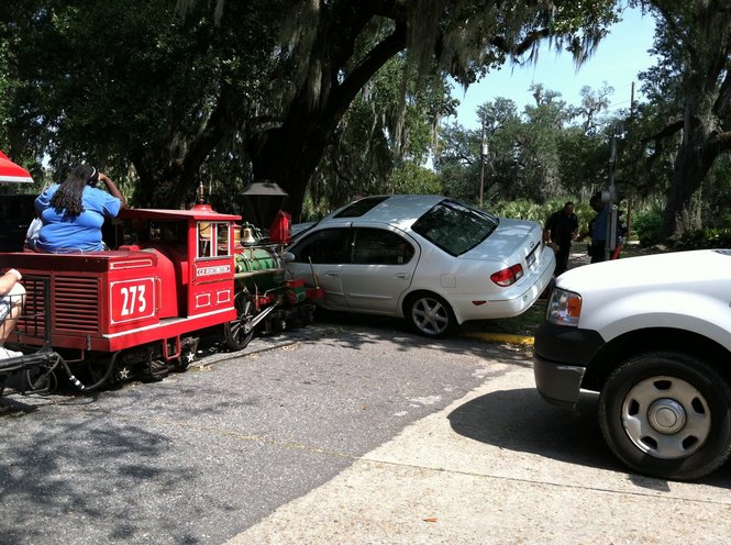
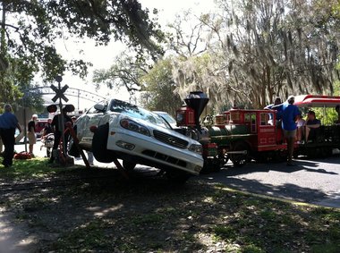
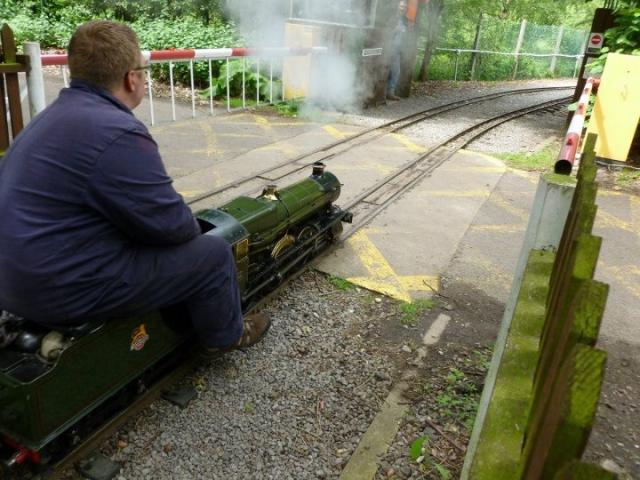
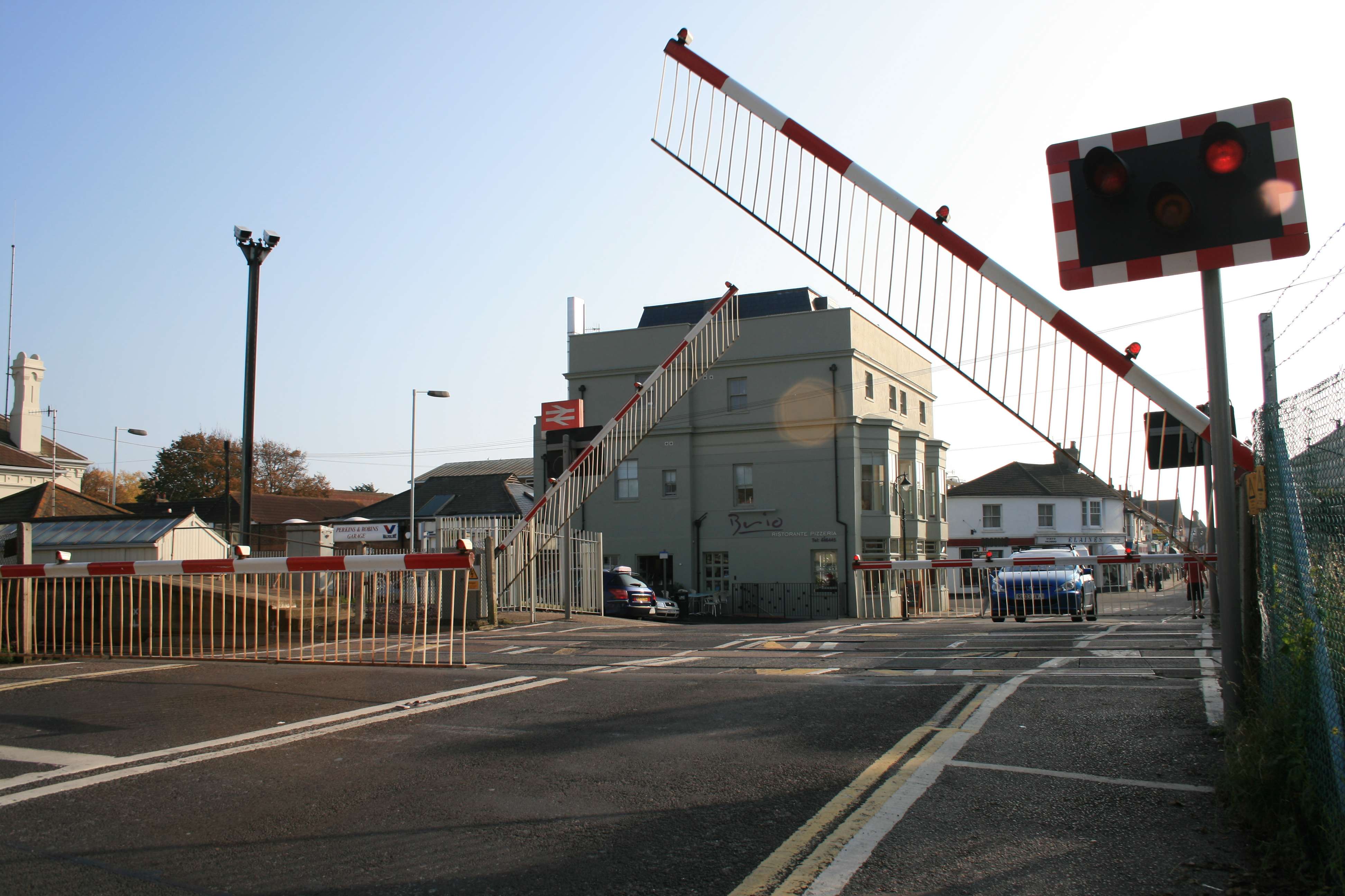
7.13 – Train chasing
713 Train Chasing
A good photo is well worth to do everything to achieve this magnificent image. Train chasing is one of the best way to capture trains in a legal way without too much people in front of your lens. Train chasing is like chasing wild animals, but a train remains predictable, a wild animal is not.
Train chasing is a nice additional to you hobby and gives a certain amount of a sporting thrill.
If you chase trains by walking on the railroad track itself without permission or without any railroad safety certification or guided and supervised by a certified railroad official, you risk a penalty and even possible to get jailed for a while. It actually depends on the local rules and restrictions in the country you live in. For example In Britain the penalty is about 1000,- Pounds fine. In the Netherlands about 140,- Euro fine.
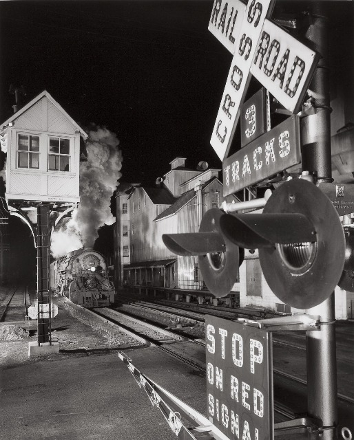
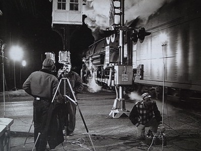
Performing photo’s like above requires special effects as well. The crew is equipped with extra lights to fill in dark spots, creating a mystical effect when steam trains running by.
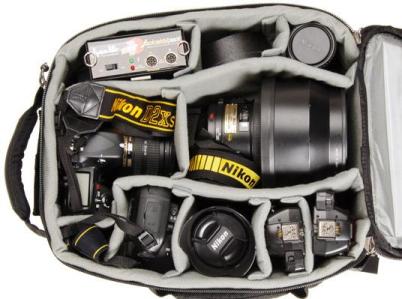

A good camera is the basic of a good photo. but remember it is not the camera, it is the person that operates the camera that makes the photo. A camera is the tool and instrument in the hands of the photographer.
Let us first look what a train chaser needs the most. Of course a common good working camera and additional material which is needed to have good results. When you are planned to go train chasing you have to meet some requirements in order to get the best results at your camera. Now the digital photography took almost over the analogue way of photography. You still have to deal with the same issues. To take care about photographical issues hereby a suggestion to buy a book about technical issues about your camera and a common book about digital photography.
In the link list (Appendix 3) there are some links to photographers with hints and tips for train chasers.
This is the “shopping” list:
- Bold printed text is absolutely required to achieve the best photo’s.
- A good (mirror-reflex) camera
- A backup battery set or battery pack
- Backup storage like SD or Micro SD (whatever your camera requires)
- A Backup camera
- A zoom lens (if your camera has the ability to change objectives)
- A Tripod
- A High Speeds flash light for light fill-ins.
To get prepared for the chasing you have to plan precisely where you want to chase the trains. It is recommendable to equip yourself with: A train chaser is busy and acts like a sporting person. So you better dressed up like a sports man, not to win the race but to catch the most beautiful image of your desired train. Plan a certain time to pop off and plan to be back at certain time. Let family, friends and/or relatives know what you are about to do in case something might go wrong.


Additional you need some of the basic equipment to get around as a train chaser. The next list shows you waht you need to do a good train.
The equipment as mentioned above.
- A good (SUV) car and/or
- An All Terrain Bike with head protection
- A second person with the same equipment or someone to support or accompany you. (Do not go alone by yourself especially when you are about to “train chase” in the nature.
- A Cell phone with an extra battery.
- A Map or street map to find the exact locations
- A safety Jack
- A hat or cap to protect your head and hair against sun, rain and on steam train chasing to protect against tiny hot ash particles and coal sparkles.
- A protection sun glass or a protection glass
- At least one flash light
- Rain coat
- Mountain shoes
- Timetable from the steam special if you chase steam specials.
- A good filed cool box with water, ice, sport drinks, sandwiches no too much if you are not able to go by car you have to carry it all with you.
- A good set of mountain shoes
- A back pack with a good lunch 94-6 sandwiches with fresh tomatoes, bacon, cheese or egg and a thermal can of coffee and some refreshments
- A map with the railroad track and road
- A perfect mood to go for it.


One of the greatest train chasers, photographers and Jazz/Blues pianist is Sir. Axel Zwingenberg from Germany. His passion for steam train is also the boost for his piano playing
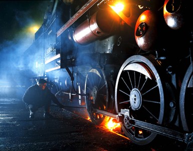
Mr. A. Zwingenberger created one of the most magnificent photo books “Vom Zauber der Züge” (The Pure Trains) ISBN 3-926398-02-7 which is even now one of the best sellers concerning the photo book.
It shows you the high atmosphere of passing trains with special light effects. From firing until the workshop, all with amazing special but natural effects using the possibilities of a qualified photo camera. When you could have a copy of this book, take that amazing photo book and you will taste and hear the music and the recorded the passing of the steam trains. For the train chasers it is a must-have and a hugh inspiration and example how to achieve these wonderful images. The book comes with a double CD. 1 CD with Steam train recordings and 1 CD with the blues piano music which is also inspired by the sound either beat of the steam exhaust.
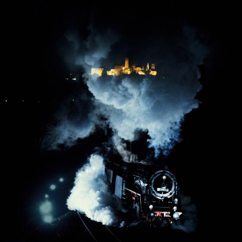
Between the 30’s and the 60’s Mr. C. Belingrodt has captured a vast amount of photo’s about the (steam) trains in Germany. His work is famous all over the world. He is one of the founders of the BDEF (Society of German Railway Enthusiasts) and after he passed away in the 70’s he had a hugh collection of photo’s which are still in use in many photo books today.
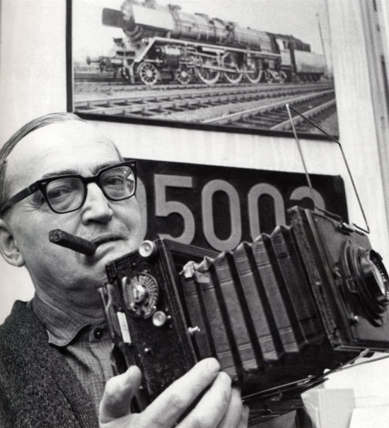
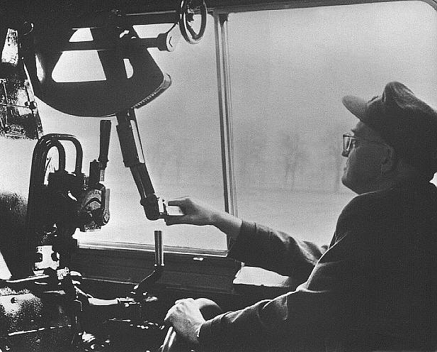
7.14*** – Railfanning, a virtual way of train chasing.
This chapter is in preparation.
8.00 – Artistic aspects and issues
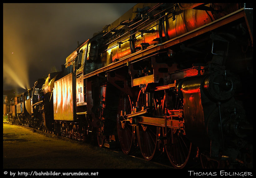
8.01 – Screenshots of Scenarios
901 Screenshots of scenarios
Mr. R.C. de Visser has amazing images telling the story within the smooth environment of the steam era in a virtual way. Here are some of his favourites screenshots and photos.

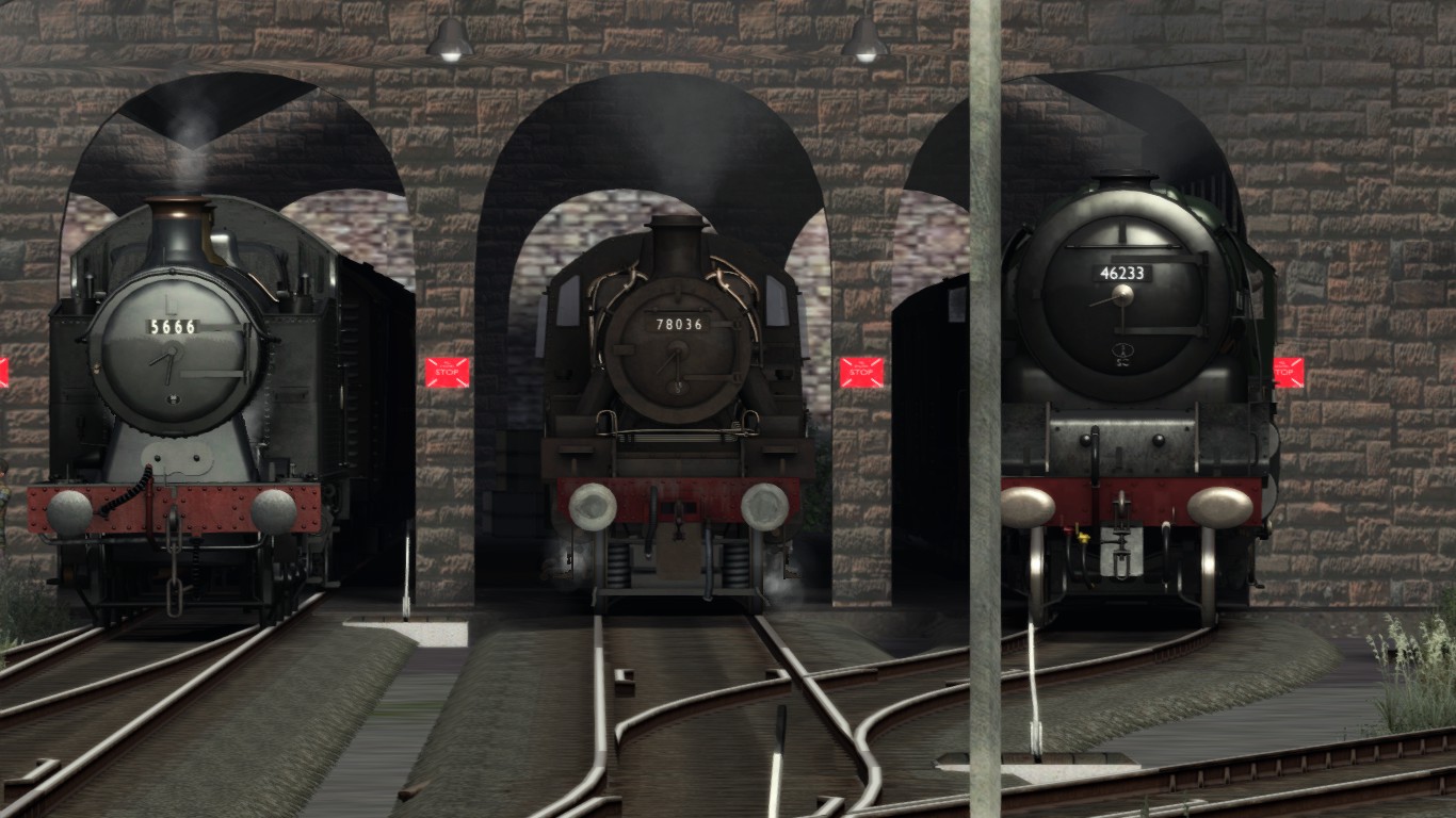

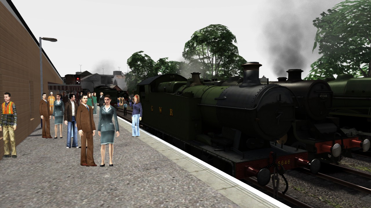
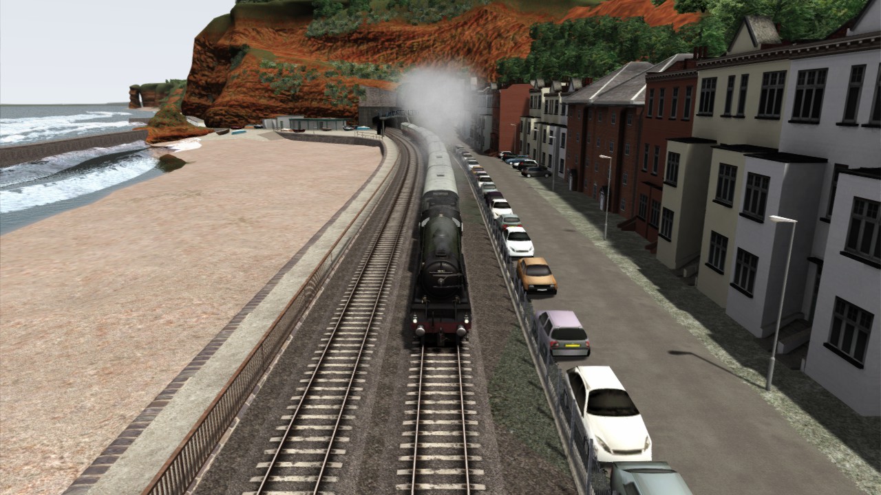

“Northern Irishman Sleeper Express”
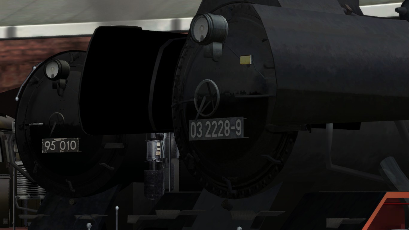
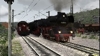
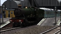
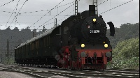
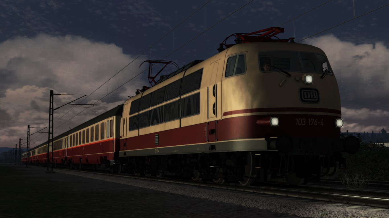
The engine and train now became available in the steam store.
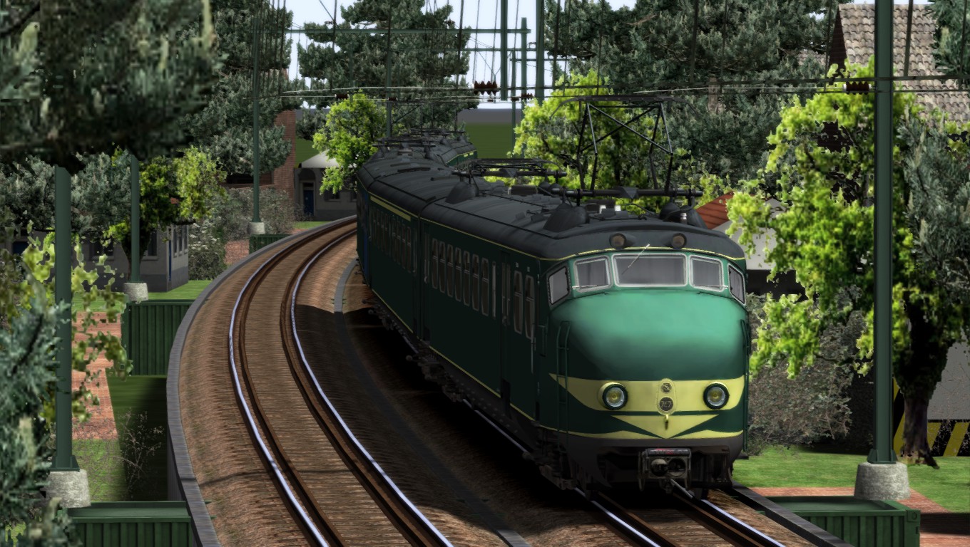
8.02 – Screenshots of route creation
802 Screenshots of route creation
Mr. N.Y de Visser is busy to create some magnificent routes. During the learning period he had create some beautiful routes . Though he encounters some problems during construction and some of these routes had to be deleted because of the crashes the editor encountered.
This routes were predestined as test. Though Mr. N.Y. de Visser catched up with it, trying to make a Dutch route.
Some screenshots of a British based route:

8.11 – Screenshots MSTS Vintage
811 Screenshots MSTS Vintage
The most train simmers has experienced MSTS already. On the start of MSTS it was the best train simulator available at that time. Now we are looking back to that decade of MSTS and we watch some of the default routes that came with MSTS. Mr. R.C. de Visser developed MSTS-Steamtrains, dedicated to the same target as Steamtrains Unlimited does today. However the name changed a few years later into Steamtrains Unlimited targeting all steam locomotives around the world between original and the tiniest live-steam steam locomotive.
The earliest virtual route of the most famous original was included as one of the six main routes that came along with MSTS. The Settle-Carlisle route is available as default route at MSTS, as add-on for Trainz and as add-on for TS20xx. Together with the Gölsdorf 380 engines for hauling the Oriënt-Express, a Flying Scotsman was included for running at the S&C line. The cab was the start and far from what it is today and was fitted at the driver’s side at the right side instead of the left. One of the first add-on’s that came available was the redesigned cab that fits better to the original cab of the Flying Scotsman.
Some later the Mallard came available at trainsim.com together with the teak wooden coaches Mr. R.C. de Visser runs a train containing these coaches and the Mallard as engine. Here are some of these images which are still available at www.trainsim.com 12 years after the creation of these screenshots.
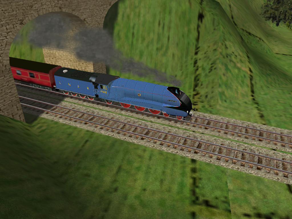

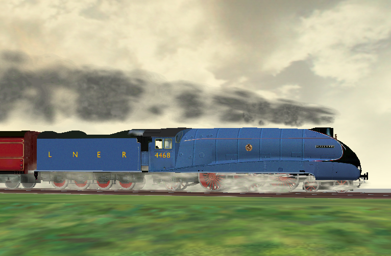
At the time of the MSTS release there was no German route at all. The first German route was along the Rhine but came out some later in addition of MSTS. After that, many routes and trains came to the MSTS shed, either freeware or payware. The Gölsdorfer 380 and the non driveable 310 were provided in the MTST installation.
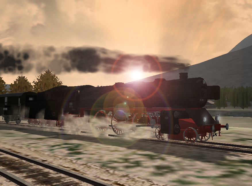
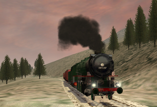
A famous name: “BeeKay” created this engine. The 150X from the SNCF. Together with the class 64. He now creates the present German engines under “Romantic Railroads” that are released by Just Trains. BeeKay created steam locomotives since the coming of MSTS,
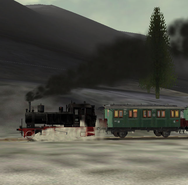
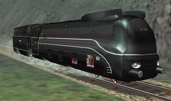
The Pacific class 01 belongs to the most famous steam locomotives in Germany.
After the separation between West and Eas Germany, many 01 were overhauled and recreated. in West Germany the 01.10 became a new boiler, oil burners and a 2’3′ T34 tender.
In East Germany they were converted into the class 01.5 with the typical streamline dome area, half streamlined side plates and some received “Boxpox” wheel sets,. The high performance boiler resulted in their long life under the DR wings. The last steam depot and shed in service was Saalfeld. In both German countries, these engines were the backbone of Express train service at non electrified routes.
The class 01.10 remained in service until the end of steam in 1977. The express train service came to an end in may 1975, the service after that was only back up for all services were needed. One of these engines is the streamlined 01 1102 and is preserved and restored receiving the blue streamlined outfit that was originally designed.
The Empire State Express is one of the rare trains that is converted to use with TS2014-2015.
Together with the Class P8 they made the step to TS2014-2015
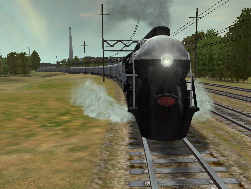
Now the end of steam in the late 50’s did replace these engines and the diesel locomotive type F7A and the diesel units F7B took over the ESE on their service.
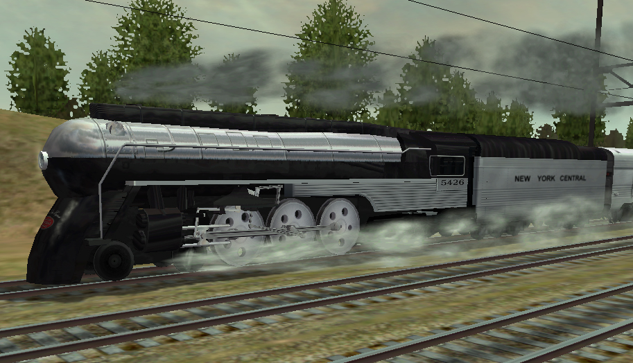
Though the SP 4449 is due to run steam specials with some of the remaining silver coaches together with other historical coaches. Sometimes together with the UP X-8444 and the SP&S 700
The most famous and biggest engine in the world was also present in the MSTS era.
Watch some MSTS screenshots during a sunset run.


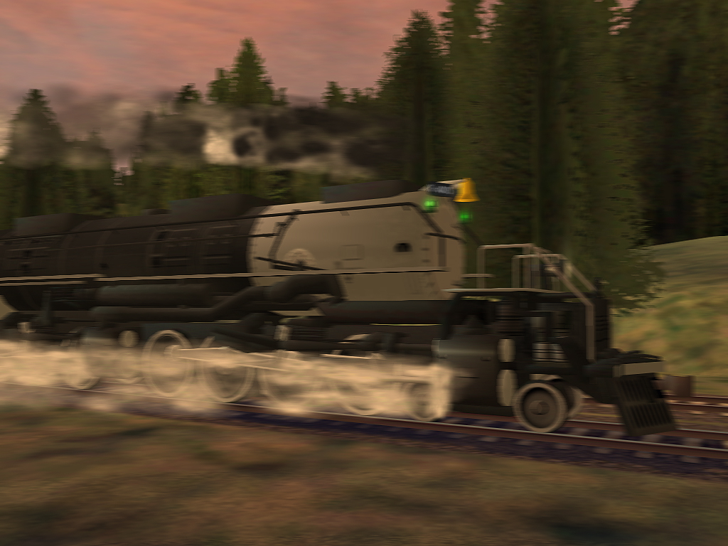
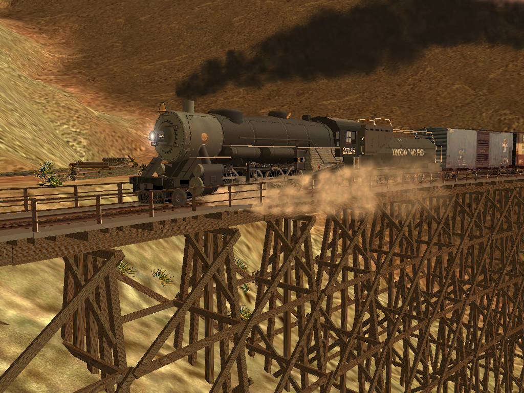
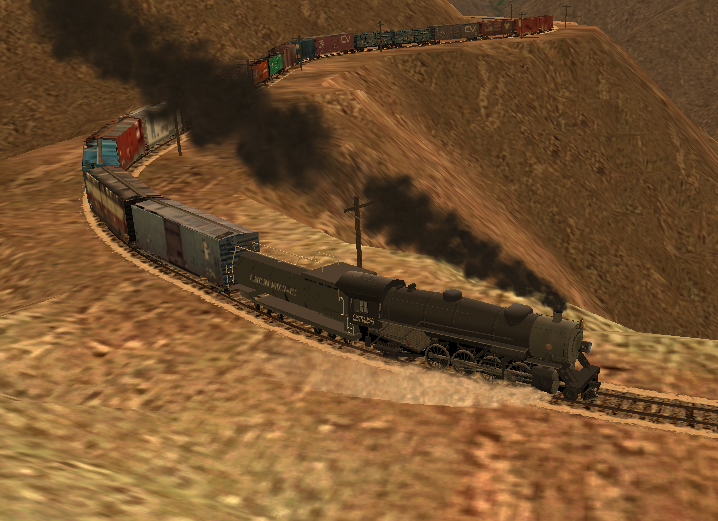


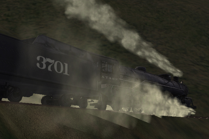
The 3701 at the Cumbre Pass
8.21 – Photo atmosphere: the best of steam trains
Enjoy the ambiance of the mystical but warm environment of the steam locomotive. The magnificent photo’s tells you in some sort of heavenly silence the beauty of the steam locomotive as it smoothly release the steam out of leakages and the smooth running oil pumps, generators, injectors and other equipment gives you the idea how it was and still is at preserved engine sheds and historical lines. The atmosphere it radiates to you, amplified your mood of passion and taste of the magnificent power of the majestic steam train on your screen.
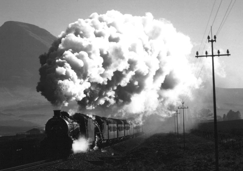
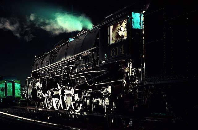
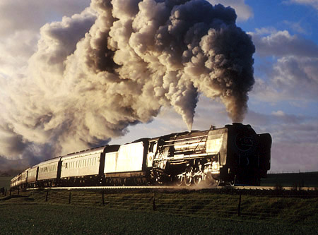
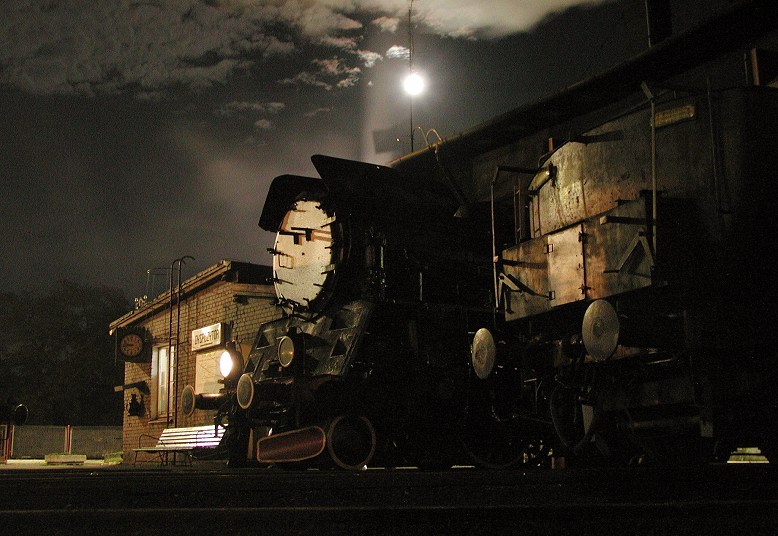
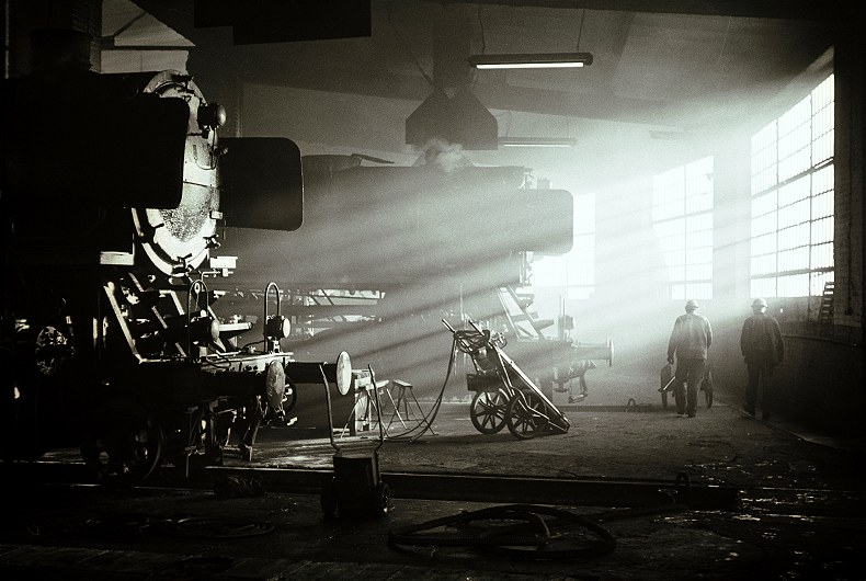
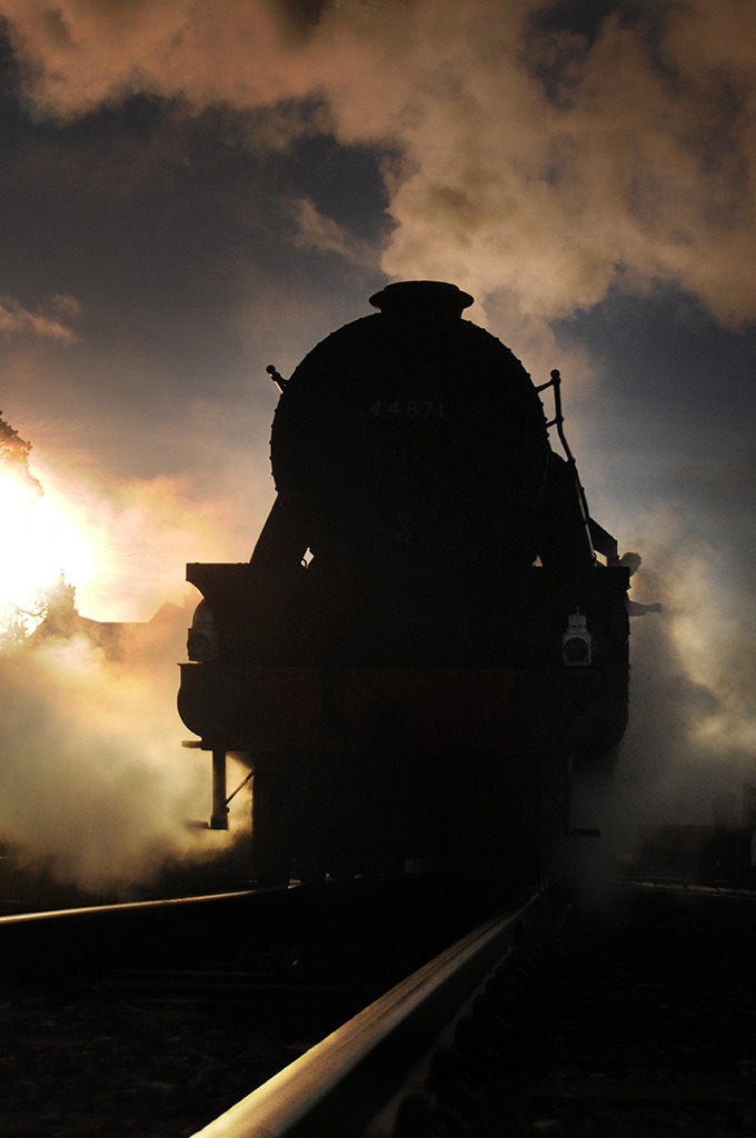
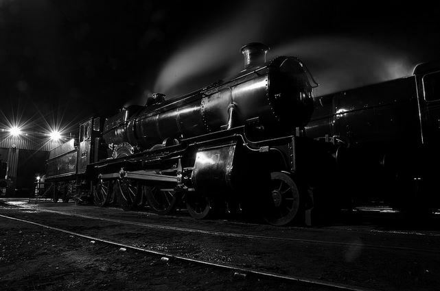


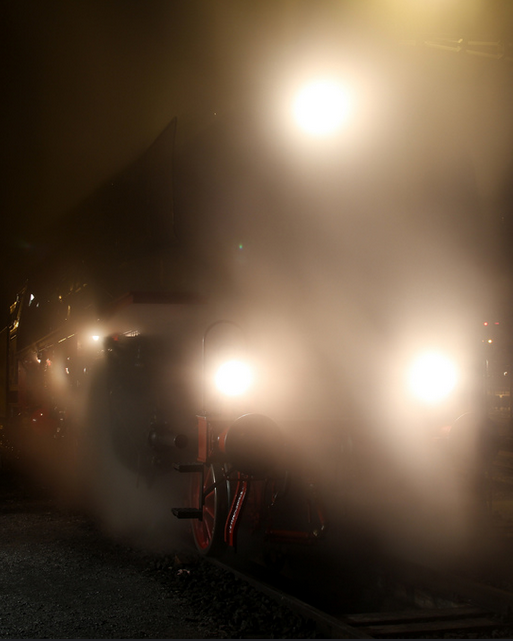
8.22 – Film atmosphere: The greatest steam trains
822 Film atmosphere: The greatest steam trains
Enjoy again the ambiance of the mystical but warm environment of the steam locomotive in video documentaries. The best available YouTube links are brought together here in this chapter to let you experience the living testimony of the steam locomotive and hear the speaking and singing exhaust, a special language that is irresistible. The gloom and glossy side effects of the video footages brings you in almost the real avenue of the ambitious working steam locomotive on your screen.
A strong advice. Play Dolby surround 5.1 and if possible beam it on the wall as large as possible and you feel like you are in it yourself. Then run a great scenario in TS2015 with the magnificent 6MT Clan Class of Just Trains and the effects are stunning. The boosted atmosphere it radiates to you, amplified once again your mood of your deepest passion and taste of the magnificent power of the majestic steam train on your screen and wall if beamed.
When a link is broken please notify via email at: [email protected] or use the link at [link]
9.00 – Finally
900 Finally
In today’s modern time, we could not imagine a world without a PC anymore. The power/current you need to run a PC comes down from a power plant, but most power plants are still working on steam through a turbine producing electricity, Some are fired by gas, some by coal. So actually your PC runs on “steam” !

Now the plain basics are revealed for you how to drive a steam locomotive properly.
You have to become aware about the technical aspects of the engines and the plain working of steam on its own to get a fully understanding the magnificent working of the engines itself.
This guide is just a little part of all techniques the steam locomotive is dealing with.
Microsoft Train Simulator has started a era just like Flight Simulator is.
An era that brings “back” the steam locomotive on your PC.
Steam is simply the best power source there ever was and still is. It is all natural and direct usable.
I hope this manual/guide will add a tremendous knowledge to your driving skills improving and increasing the fun of simulation.
A steam locomotive does not require a computer to run, but it does require your knowledge.
Do not forget to rate this guide at the engine-drivers site.
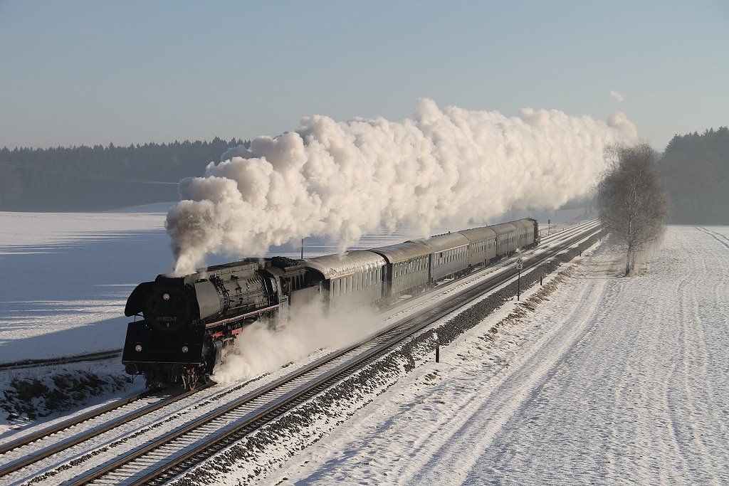
Driving a steam locomotive is a “game” between feeling, skills, knowledge and (inter)action.
The feeling however is not translated into a PC. The best you can experience the thrill is become a member of a steam club with driveable preserved steam locomotives.
Start to take a old shred and start polish the steam locomotive prior to a run or service on a steam line somewhere. Just polish the magnificent engine with simple shred. You will discover a lot of items and features you did not know it even exist. Then ask the experienced driver or fireman what the device does and how it world. He will explain it all to you. Then offer yourself to help firing up the engine. You become skilled after a several times firing up prior to a run.
When you do you best. You will be added for the course firing the engine. The best way to discover and learn the mystical working of a steam locomotive. You will love it.
Steam runs into your brains and all the nerves in your body will be steamed up.
At the moment you stoke the engine on a run, you will feel the engine, the thrill, the joy,
the pain and the passion, in summer and winter. Then you know what it really is how to stoke, drive and run a steam locomotive.
Mr. R.C. de Visser, born in Rotterdam, the Netherlands, in 1965. Father of 3 kids. Becomes passioned of steam trains since very early age. Is owner from Steamtrains Unlimited name and website. Has seen the steam locomotive running in Germany in the 70’s. Started train simming when MSTS was released. Builds scenario’s in TS2015 at the PC of his son.
Has been a member from: “Stoomgroep West Zuiderpark”, drove many times with steam at 7 1/4 inch live steam miniature railway in The Hague from 1986 untill 2008.
He was a member from the “Stoom Stichting Nederland” from 1995 until 2008 keeping German engines in active preservation, restoring, preparing, stoking and firing up. He regained membership in 2015.
He has translated the “Leitfaden fur die dienst auf der Dampflokomotiv” into Dutch for educational purposes at SSN. He has been many times on the footplate of SSN steam locomotives during Steam Specials as 2nd fireman.
Mr. N.Y de Visser, Born in Rotterdam, the Netherlands, in 2000, son of R.C. de Visser.
Owner of the TS2015 on his PC, sharing TS2015 with his father, experimenting route building.
Loves local and suburban transportation and modern trains like TGV, Eurostar, Metrosystems and tramways.
He is a school student and also loves flying as well using Flight simulators.
Though we are Dutch, we choose to use and maintain this guide in the English language, and not without a reason. It is the goal to reach the train simmers, train lovers, passionate steam train fans all over the world with an amazing guide about driving steam engines using TS2015.
We could write or recreate this guide on Dutch and German as well, but the vast majority speaks English. There is a tiny Dutch a locomotive fan group and the most of these group speaks English as well.
Sincerely,
R.C. de Visser – steamtrainsunlimited.webs.com
N.Y. de Visser (natanaelf86)
Visit steamtrainsunlimited at [link]
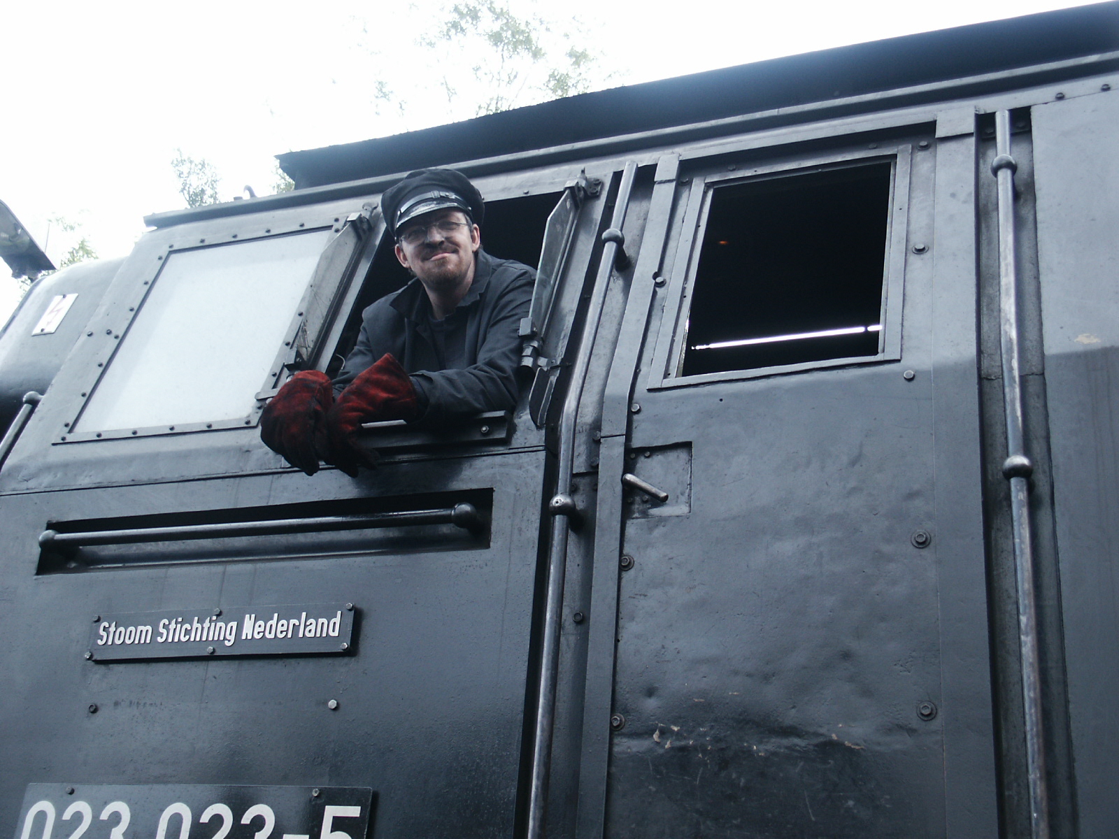
List of personal favourite Engines at TS2015:
Steam
– 4MT and 6MT Advanced
– German class Br01, Br03, Br38, Br52 and Br95
– FEF-3, Daylight, Big Boy and Challenger
– The Coronation
– Tornado
– Flying Scotsman
– A1 family “Mallard”
– Black 5
– King Class (similarity with NS 3700)
– Pannier Class
– 9F Evening star
– J94 (alias NS8800)
– 56xx Class
– GWR Steam car
Electric
– Br E03 and Br 103
– Dutch Classics in old colours
– Class 421, Class 422,
– Class 76 (Tommy)
– Class 77 (alias NS 1500)
– Br E18, Br E94, Br E10 and E10_12, Br 151 (Green livery)
– GG1
Diesel
– V200, VT08, F7,
– Class 37, Class 20, Class 27, Class 40 Class 55, Class 08, Class 11(Family of NS 500) Class 111, Class 117 all in the green Livery (green chapter)
Furthermore all trains and rolling stock that fits the steam era particularly.
All routes are in TS2015 unless notified otherwise
United Kingdom:
– All Lines in Scotland
– Falmouth Branch line
– Somerset and Dorset
– West Somerset Railway
– Mid Hants Railway
– Settle-Carlisle
– London-Brighton
– West Main Line over Shap
– Great Western Mainline
– Great Eastern Mainline
– Local traffic in the southern region of England (MSTS)
– Severn Valley Railway (MSTS)
– The Swanage route (MSTS)
Germany:
– Ruhr Sieg Line
– Köln-Koblenz
– Hamburg-Hanover
– Im Koblitzer Bergland
– Three country route
– Black Forrest line
– Munchen-Garmisch
– The Emsland Route (MSTS)
– The Rollbahn 1963 (MSTS)
– The Werratal bahn (MSTS)
– Koblenz-Trier (MSTS)
USA Routes:
– The Horseshoe curve
– New York-New Haven
– Sherman Hill
– Cajon Pass
– Cumbre Pass (MSTS)
– North East Corridor (MSTS)
USA Compagnies:
– Union Pacific
– Pennsylvanian Railroad compagny
– Southern Pacific
– Santa Fé
German educational books and sites:
“Leitfaden fur der dampflokomotivdienst” (Niederstrasser)
“Eisenbahn Lehrbucherei” (German Federal Railway)
“Die Dampflokomotive” (Transpress)
“www.dlok.de”
“British Rail” Historic Educational Movies at YouTube
Thirth Party Video footages at YouTube
Freely translated, interpreted and edited by: R.C. de Visser
10.00 – Appendixes
1000 Appendixes
All links, resources and libraries are mentioned here to create an open access to more information where ever necessary to increase the knowledge of your hobby.
Not only for the hobbyist, but also practice for the professional
10.01 – Apendix A: Keyboard operations overview
The keyboard overview is roughly for all tractions quite the same. In this short overview you will find a list of all common keys and additional keys regarding all functions to operate a steam locomotive.
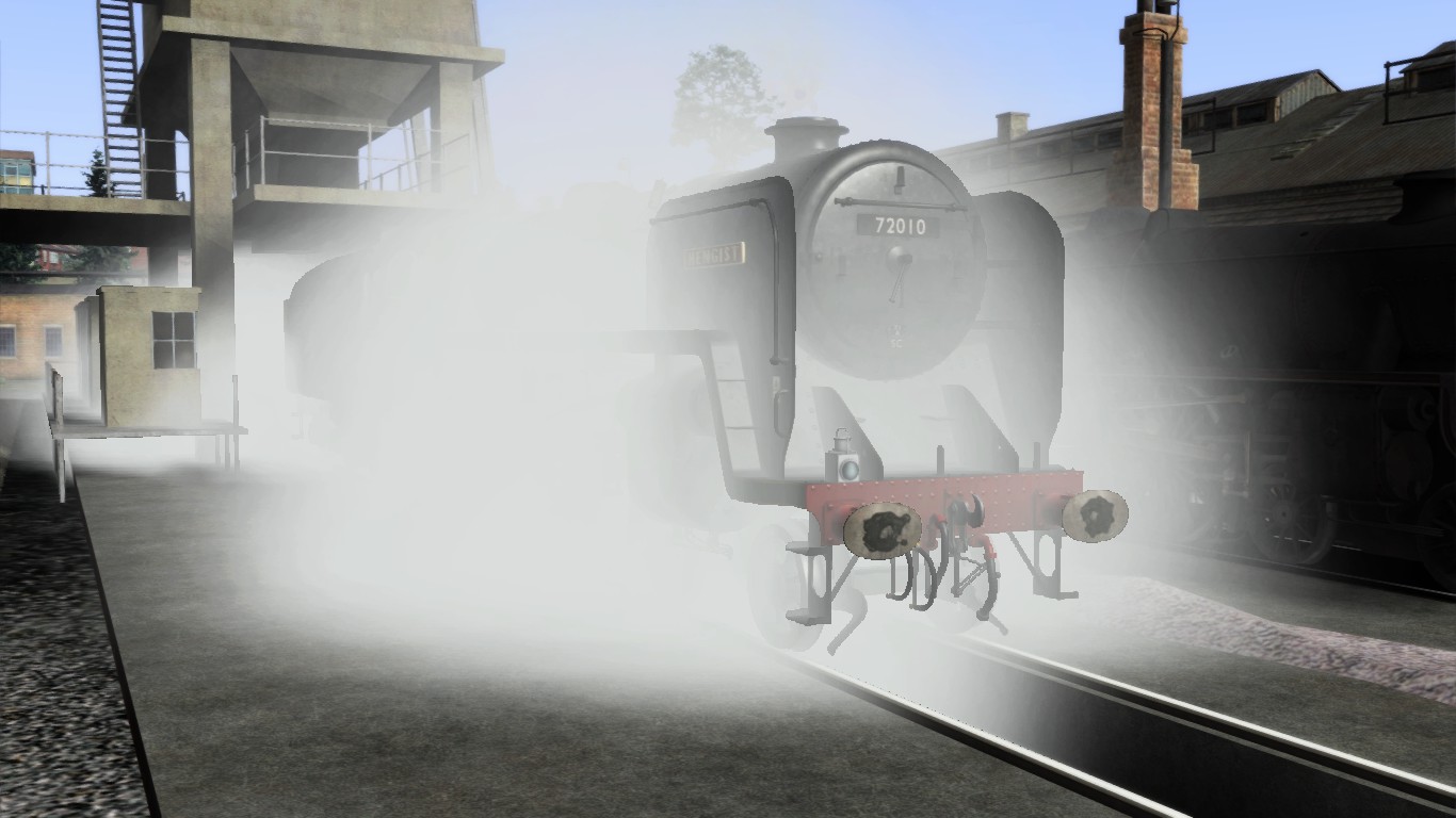
The mentioned list of key operations will contain a chapter which is in relation to the function. However in this chapter there is no further explanation.
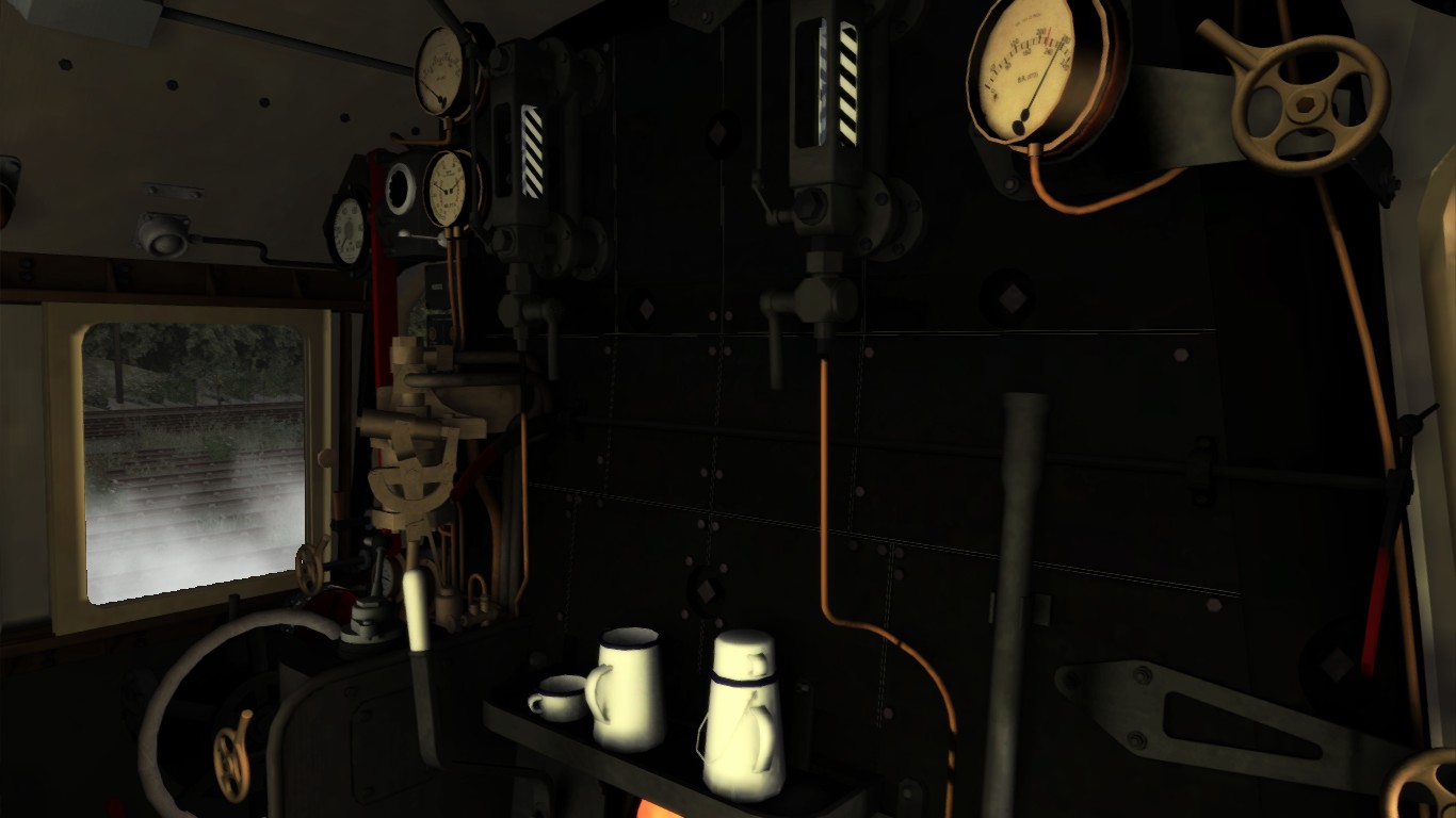
10.11 – Apendix B: Railroad definitions, names and phrases
This Chapter remains in overview
Every railroad in every country has their own definitions that defines all materials and structures by name to avoid any misunderstanding.
A train:
(Un)powered rail vehicles, connected with each other that is to be transported along a guided rail system.
A locomotive;
A powered rail vehicle, not suited for passengers and/or freight transportation, submitted and capable to put a train into motion along a guided rail system.
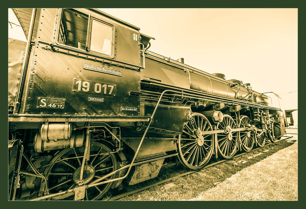
Freight:
Cargo means in the widest definition; could contain livestock, chemicals, containers, bulk load, parcel, food and other materials but no human beings.
Passengers:
Humans to be transported using a vehicle
A Point, a single slip or a double slip
A technical construction with moveable parts in the railroad to made is possible for rail vehicles to shift from one track to another.
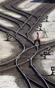
A cross-over:
A technical construction without moveable parts in the railroad to made is possible for rail vehicles to shift from one track to another and crosses another track.
A catch point:
A technical construction with moveable parts in the railroad to catch uncontrolled and run-away rail vehicles to prevent these vehicles to run onto the mainline.
A frog:
A technical construction in a point, single slip, double slip to made it possible for the train wheels to run over it without derailment.
A contra rail:
A piece of rail which keep the train wheel in place at the opposite of a frog preventing derailment
A signal:
A technical construction able to show a certain designated sign or signal to communicate in one-way with the driver.
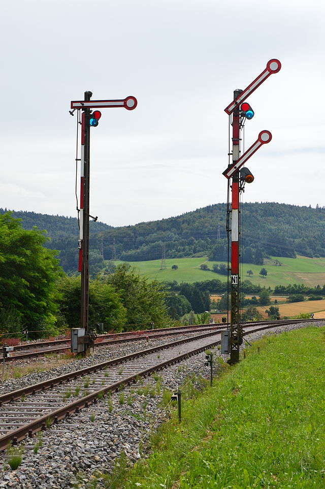
10.21 – Apendix C: Resources and libraries
This chapter contains an overview from all resources as used in this guide.
- The English title of the books is shown underneath the original name.
- The ISBN referral number is noticed as well if needed for ordering at your local bookstore.
- Mention that the original books does not contain English translations if the book(s) you order persist in a foreign language.
[/i][/list]
____________________________________________________________________________
Deutsche Bahn AG / Deutsche Bundesbahn / Deutsche Reichsbahn
German Federal Railroad: Eisenbahn Lehrbucherei:
- Dampflokomotivkunde.
The knowledge of steam locomotives
ISBN: 3-856498-99-0 - Der dienst der heizers.
The firemans stoking shift
ISBN: 3-923967-01-2 - Betriebsmaschinentechnische Anlagen für Dampflokomotiven.
Operational equipment for steam locomotives
ISBN: 3-923967-00-4
____________________________________________________________________________
Guide for the shift and service at the steam locomotive
ISBN 3-921700-26-4
ISBN: 9-783344707-91-0
ISBN: 978-3-92240-403-3
ISBN: 978-3-92240-404-0
ISBN: 978-3-92240-406-4
ISBN: 978-3-92240-410-1
ISBN: 3280013062
[/list]
____________________________________________________________________________
ISBN 3-926398-02-7
[/list]
____________________________________________________________________________
The steam locomotive, part 1
ISBN 9-062723-61-6
The steam locomotive, part 2
ISBN 9-062723-71-3
The Dutch steam locomotives
ISBN 90-6013-262-9
[/list]
Steam locomotives NS 3900
ISBN 97-89071513-75-6.
Steam locomotives NS 6100
ISBN 9-071513-43-2 .
____________________________________________________________________________
ISBN-13: 978-076033881
[/list]
____________________________________________________________________________
[/list]
____________________________________________________________________________
[/list]
____________________________________________________________________________
10.31 – Apendix D: Links
This additional page is regularly overviewed and new links are being added when internet sites are worth to add. A link to an internet site is added when the internet site mainly provides (technical) information about steam locomotives and if possible directly inherit the steam locomotives that are included in the available DLC’s and add-on’s that are TS2015 (or in some cases MSTS) related.
- DGEG – Aufbau und technik der dampflokomotive. (German)[dlok.dgeg.de]
- Stoomstichting Nederland (Dutch)[www.stoomstichting.nl]
Live steam clubs are present in almost every country. The advantage of miniature railway engines is the technique which is the same as the original. Secondly everybody can purchase or build their own engine based on original drawings. Engines up to 15 inch are uch easier to manage, maintain and strong enough to pull passengers on a large train. These models are real working steam powered engines mostly a copy of the original. This models keeps the steam era also alive and pays a hugh contribution to the originals as well.
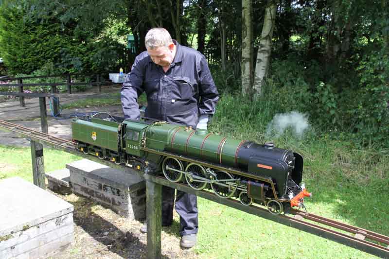
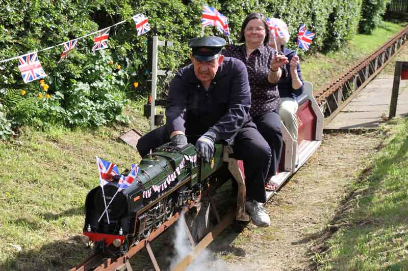
- Deutsche Gesellschaft für Eisenbahngeschichte[www.dgeg.de] (Germany)
- Ulmer Eisenbahnfreunde e.v. (Germany)[www.uef-dampf.de]
- Sir Nigel Gresley Trust Ltd. – United Kindom [www.sirnigelgresley.org.uk]
- Maxitrak[www.maxitrak.com]
- Steamdays[www.steamdays.co.uk]
- Steamworkshop[www.steamworkshop.co.uk]

Live steam miniature railways brings the technique of steam almost into the living room.
When you have a spacey garden you can even build your own live steam railway capable to haul passengers. Though TS2015 is not directly related to Live Steam, Live Steam offers the capability to understand the technical insight/
- Damfbahnclub Deutschland (Germany) [www.dbc-d.de]
- Live Steamclub Auenheim[www.dampfbahnclubauenheim.de]
- Live Steam club Taunus[www.dbc-taunus.de]
-
Stoomgroep West Zuiderpark Den Haag The Netherlands[www.stoomgroepwest.nl]
- GM Rail[www.gmrail.co.uk]
- Railway technical[www.railway-technical.com]
- railsigns[www.railsigns.uk]
- signalbox[www.signalbox.org]
- Stellwerke (German)[www.stellwerke.de]
- Headcodes[www.semgonline.com]
- [link]
- Head- and Bell codes[myweb.tiscali.co.uk]
- UK Trainsim[www.uktrainsim.com]
- Railworks America[railworksamerica.com]
- Photographer R. Peters[www.richardpeters.co.uk] Nature/wildlife photographer