Overview
This is a guide on how to add cosmetics to the game and you might be wondering what this can do that Capnbubs’ Hat Modding Guide doesn’t already?Well I thought that his guide, while awesome and enabling me to get to this point, is lacking a few things.For one it left me wondering how to get create the asset in the first place and then it hasn’t been updated to WOTC, so I figured I would make a COMPLETE guide on how to add helmets into the game and you can take it from there :)From reference through modelling to texturing, scripting and release.
Introduction
That means I’m going to cover almost everything from finding a reference to modelling to texturing and scripting as well as publishing. That also mean that the guide is going to be very long, but the whole process really isn’t as bad as it may look.
The steps to make this stuff aren’t that hard (honestly), but it WILL take you time to get to a point where you are comfortable (and lots of it) and you WILL get frustrated along the way.
But at the end you get a sense of achievement that will carry you forward and each step you take will make the next seem less insurmountable. Once you do it a few times it’s really not that difficult to make stuff, ambition notwithstanding of course.
1. Where do I start?
This is step where a surprising amount of people already run into trouble.
You’re going to want to start with an idea, something small, simple, and you want to have a pretty good idea of what it is you want.
It’s ok if this never makes it into the workshop, just start SOMEWHERE. My first attempts had nothing to do with what I was ultimately aiming for but gave me the confidence to go on.
In this case I chose to make one of them iron mohawks from necromunda. With which I am in no way, shape or form involved, that’s all Games Workshop. This is an entirely unofficial guide that just happens to base itself on one of their products:

It’s a fairly simple shape and doesn’t have much going on in the way of texturing.
I’m serious, it’s a cube, that’s stretched lengthwise with a slice of pizza on top on top of it.
That’s pretty much the gist of it. When you try to see it in shapes, it’s much less intimidating.
2. So you have an idea, now what?
You’d think you can start modellling now, but before that, you should open the XCom editor and export a Soldier head to work around and also some hat that is similar to what you want. That can be glasses or so too, it doens’t need to be an actual helmet.
Similar in this case means something that is about the same size but mostly means what kind of hair is it using?
This is because hair doesn’t simply flatten like it does in real life, instead some parts of the hair are removed.
Let’s take a look at the classic Guile hair. On the right you see the normal hair, on the left what the same hair would look like for a baseball cap for example.

For this tutorial, I don’t care and I’ll pick somehting with normal hair, the player can just pick bald hair later.
I’m not going to explain how to install Modbuddy, there are other guides out there that cover this step.
It’s normal to get a little frustrated at this, it’s a task and a half. You only have to do this once though, so bear with it. After installing you really “only” need to set up the path to your game directory and probably run modbuddy in admin mode. You can get it via tools in your library (yes, there are subtpyes other than your games 🙂 )
So now, how to actually export a model?
Open modboddy and once in there, open the xcom editor.
The two are separate tools. There is going to be a bunch of warnings and load errors but you can ignore those.
What you want now, is a skeletal mesh, so select that as a filter on the top and search for “headband”.
There will be a bunch of hair and somewhere near the bottom you’ll find “SM_Hat_G_Headband_M” and “SM_Hat_G_Headband_F“.
The female and male models are different so you might need to make one version for each. Sometimes it won’t be an issue though, that depends on what you’re making.
You only need to export one either way though, we only need the bones that come with it, which are the same for both sexes.

For now, let’s just do the male version. Right click and export to file. Put it somewhere you can find.
Ye’re also going to need a head to work on, so search for “head”. I will be using SM_Head_reference.
It doesn’t really matter which one you pick, so long as it resembles the head you want to make stuff for. You’re not going to use it for anything other than a guide.
At this point you can close the modbuddy and the editor, we won’t need them until much later.
3. Set up blender before we start modeling.
You’re most likely going to want to get Blender for the modelling. It’s pretty decent and free though it can be a bit overwhelming at first.
One thing I can recommend from the start, is to use keybinds, they are absolutely crucial to working with Blender, so try and get used to them from the beginning.
So once you’ve downloaded that, you will be greeted with the following scene:
What you get is a cube, a light and a camera. We don’t need either of those, so select all (A key) and delete them (X key, because reasons).
You’re going to hit “A” twice. The first time you will deselect since the cube was already selected and then hit “A” again to select everything.

Now let’s import the head and headband.
Go to file and import -> fbx.
One you have the two it should look somehting like this:
That’s a bit hard to work with so let’s hide everything and then only show what we need.
Select everything again with “A” (twice), then hit the “H” key to hide everything that is selected. (“ALT + H” to unhide stuff)

Now let’s only show the head we are going to model on:
Find the head in the scene browser (top right) and click on the eye to show it.
That’s much more managable, but it’s also pitch black and that’s not helping .
This is because it doesn’t export the materials properly, so let’s assign a new one.
Select the head in the scene browser and go to the material tab (under the scene browser):

Click on the plus sign to add a new slot. This won’t do anything yet, we need to add a new material into this slot.
So click on the new button. Now we don’t need the old ones so just get rid of those by clicking the “-” sign.

You should be looking at a white head now.

All set 🙂

4.1 References
Oof, about time.This is a long one. First we need to make a high poly version.
This will give us some nice lightning and details later one without actually having that detail on the model.
Deselect the head by hitting “A” again, otherwise the next part will be added as part of the head, which we don’t want.
It’s nothing that can’t be easily fixed later but let’s get it right from the start.
Now create a cube by hitting “SHIFT + A” and selecting Mesh -> cube.
Now’s probably a good time to explain some basic commands. No need to memorize them, you’ll be using them a lot.
Just come back there if you forget them. I will be repeating them across the guide.
Command references:
First of there are two different modes you want to be aware of: Object mode and edit mode. (switch with TAB, or in the bar at the bottom of the 3D view)
Object mode does not allow you to choose faces and such, most edits will be done in Edit mode.
Also VERY IMPORTANT, NEVER undo in obect mode. It won’t break anything but blender keeps a stack to undo.
Undoing in Object mode will clear that entire stack, meaning you can’t go back in steps anymore and loose the ability to redo. Basically, it is a major pain in the backside.
Also be aware of this stack as it may mean you can’t go back all the way anymore, especially if you individually selected vertices as each will count as one layer on the stack.
In short, save after every major step and be careful where you undo. Sometimes it’s easier to try something out and NOT save and if it turns out meh, just load the last save. You don’t want to be caught with your pants down and realize you can’t undo back all the way.
“Movement”
Middle mouse button let’s you rotate the camera around you’re current focus.
Shift + middle mouse button let’s you pan up and down.
“Zooming”
Scroll wheel let’s you zoom in and out, but it’s not moving the camera.
CTRL + middle mouse button let’s you move the camera itself closer.
Comma (as in “,”) ON THE NUMPAD moves the camera to your selection, you’re going to use this one a lot.
“Selection”
Right clicking is what you use to select something in the 3D view. Shift + right click to deselect
Another way to select is hitting “C”, this will bring up an circular selection.
Scrollwheel allows to increase and decrease the size. Very useful with wireframe mode to select overlapping vertices
Left clicking will continuously ADD selection, middle mouse button will REMOVE selection.
Aternatively, hit “B” to draw a marquise. This will also only add, unless you select with middle mouse button.
Also very useful is “ALT + right click” to select a continous loop of stuff. Depending on where you click it will be lateral or vertical.
“Basic mesh commands”
For ech of these you can hit “X”,”Y”,or “Z” after hitting the respective keys to restrict them to one axis and they also take numbers.
For example “R”, then “X”, then typing 90 will rotate the mesh 90 degrees around the x-axis.
Also you can right click at any time to cancel whatever you’re doing. Useful for moving a vertex around to see if there is a double underneath but you don’t actually want to move it for example.
“G” will allow you to move your selection.
“S” will scale it.
“R” will rotate it.
“Bread and butter”
“E” will extrude.
“I” will inset
“W” has a set of common commands.
“CRL + E” has a set of common commands for edges.
“CRL + TAB” allows to switch between faces, edges and vertices. You will be using this ALL the time.
“N” for the properties tab
“T” for the tools tab if you ever loose it or want more screen space.
“Z” to go to wireframe mode, sometimes easier to work with and let’s you select stuff that would be otherwise hidden.
Ok, now, let’s get rolling.
4.2 Making the basic shape.
Scale the cube down “S” and move it over to the head, you can also use the arrows to move stuff.
Red is X, green is Y and blue is Z.
Keep your reference close:
In fact depending on the refrence you can even import it and draw over it, that’s a really big help.
But this is all we have and it’s not a complicated shape so eh, it’s strip of metal with a fin. We’ll be fine 🙂
I’ll start by blocking out that triangular piece just above his eyebrows. It doesn’t need to be pretty yet. We’re just laying out the general shape/position for now.

Now we have a place to start from, let’s add the plate that would connect to his skull and from there we can pull up the mohawk.
Select the faceof the cube pointing up towards his scalp and extrude a couple of times (“E”).
Don’t go crazy about getting a nice curve, you’ll see why later, just try to keep the the thickness kind of even…ish. You can follow the skull for this, you’ll see quite well where it has to connecting faces, it is far from being round.
Something like this:

Now let’s add some edges that will become the mohawk itself. A great tool for this is to use “CTRL – R” which will add a loop around.
“CTRL -R” to select which way to flow (move your mouse around and you’ll see what I mean), then add loops with the scrollwheel and left click. This will allow you to move them into place, the middle is fine so just left click again, or right click to cancel the placement (they will still be placed).
They will be evenly spaced but I prefer to have it a bit thicker so while they are still selected, scale them along the Y-Axis. “S” -> “Y”
While you’re at it, you can also add a loop near the triangle just above where that knob is so you have some space to add that later. If you need it that is.

Now you’ll want to select the faces where you want the hawk to come out and extrude the faces (“E”).
Preferably at least twice to get a bit more geometry to work with.
Should look something like this:

That wasn’t too bad now was it? Already it is resembling a thing.
For the crest, you basically want to create a T shape on top of the faces we just extruded.
- You’ll want to inset those top faces with “I” to get that sligthly inset part under the crest. Then extrude upwards again on those inside faces. This is the thin part just under the crest. It’s the same as we just did.
- Then once more, extrude on the top, this is going to be the crest itself. It is too thin right now, so select the sidefaces of that top ridge and extrude those sideways.
You’ll want to manually adjust the front and back as they will be overlapping. For this, it can be helpful to be in perspective mode.
This can be done via “5” on the numpad key, and then “1” is a sideview, “7” is a top view and 4,6,8 and 2 let you rotate these.
Combine with wireframe mode “Z” to line everythign up and select both sides with “C” for example.
When in persepctive mode like this you don’t have to wory about the other axis’, so you can drag and drop so to speak. If you do that outside of this perspective, you will be moving in all directions somewhat uncontrollablly.
At this point I also decided I didn’t like the curvature so I went and changed the shape a bit doing just that and poking and prodding the vertices until it looked right. It’s only moving parts up/down/left/right, but it takes some time.
Changing things is normal so don’t be afraid because it seems like a lot of work

Now, spikes! Bear with me here. We’re doing another extrude in the same way as before so, I’ll skip that part.
For this next part, another tool is handy: Hit “G” twice and you can slide vertices along an edge without changing the overall shape. You might even be able to do multiple spikes at a time with this.
- For the spikes we’re going to need a bit more geometry to work with or the base of the spikes will be too large and they will touch each other. So add a few more loops around with “CTRL-R” to divide the ridge into more parts.
- That will also allow us to improve the curve a little bit. Then add one loop down the center and extrude the new faces.
- Except, we want spikes and not rectangles, this aint the mechanicum…unless you want to cheat 🙂
Select the vertices that make up the corners of the spikes and slide those closer to the center of the spike. Reapeat for the top and just kind of wing it from there. - Poke around until they resemble spikes 🙂
The end result should resememble this:

If ever get an issue that you can’t zoom in enough like this:

You want to reduce the clip setting in the properties tab “N”.
By now our mohawk should really be coming together.
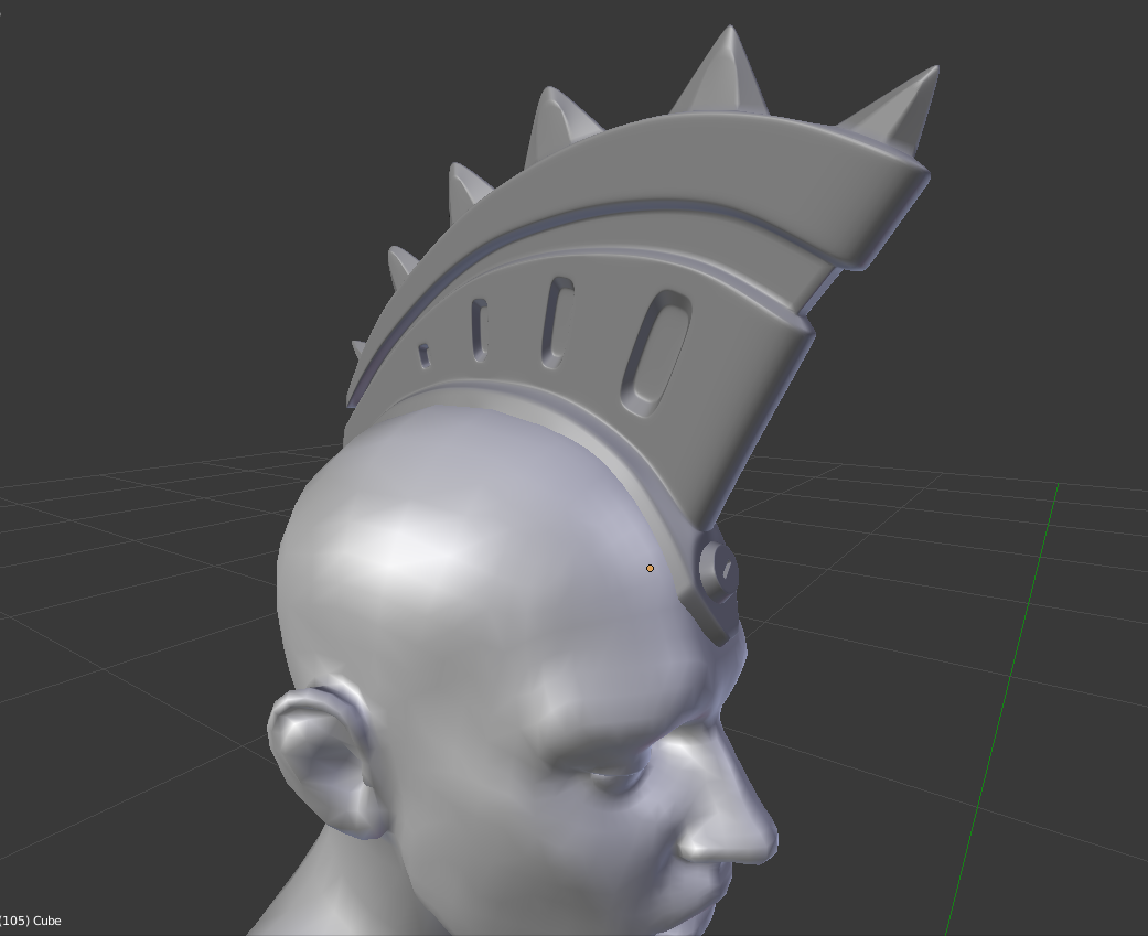
4.4 Almost there!
This is where we left off:

I’d say we’re getting pretty close here, but aside from the knob that I presume screws it into his skull, we are missing a key component to make this our high poly version.
What we’re missing is a subdivision modifier.
What this does, is use our existing blocky mohawk as a cage of sorts to make a MUCH more detailed and curvy/softer shape wihtout actually having to work with that much geometry.
Go to the modifier tab and add a subdivision surface.
Pump the view and render value to 3 to give some nice detail without requiring a nuclear powerplant to run it. Be careful with this setting, going further than 3 is a serious preformance hit.

We still see all those hard lines, which we need to get rid of to get good lighting.
Go to the tools tab “T” in object mode “TAB” and with the mesh selected, under Edit -> shading you’ll find smooth.
Now we have a babysmooth surface. Too smooth actually and we lost a lot of detail.

There are two ways of dealing with this. Either you add more edges where you want edges or you select the edges you want to be crisp and increase their crease weight.
You can see the crease setting when you have an edge selected and look in the properties tab “N”. This is the easiest but usually only looks ok when it is a really sharp edge, which is most of the mesh here.

You get more control with adding edge loops. The front of the mohawk looks like it should be rounder, so I’ll do that with edge loops.
Notice the areas highlighted in yellow, that’s where I added edge loops with “CTRL + R”. They look much better than the creases, but they make the mesh harder to work with and can cause issues with UV mapping later.

So I suggest to use both as you need them. Creases when you can get away with them and loops for quality and finetuning. The closer an edge is to another, the more defined an edge will be and you can add loops from both sides.
Here I had to come from both sides to get a nice crisp transition and at the same time I got a nice little lip for the bolt to sit on.

So with a few extra loops and some creases you should be looking at something that almost looks done. ( and manually fixing the blocky base plate because I forgot to adjust that when it was still easy…)
Now to bring it alive and take it to next level. (and completion)

4.5 Details
I’d say that’s close enough for the general shape, now let’s add those indentions along the side of the hawk. Though these are fiddly and thus optional. ( There are better ways of doing this but it’s good practice :P)
- Select a couple of alternating faces and inset them “I”.
Now, I’d suggest to go back to side view “5” -> “1” and make these faces all nice and square by scaling them as follows:
Select horizontal lines for example and scale “S” along Z (hit “Z”) and hit the zero key “0”. This will flatten them. - Once that is done with all of the squares you can rotate them as necessary and move them into place.
- Finally inset them again “I” and extrude “E” them inwards.
If you don’t inset twice, you’ll find the lip to be quite subtle. The first indent acts as an edgeloop for the groove. The extrude is best done by selecting both sides and applying the extrude immediatly, then scaling along the Y-Axis:

For extra definition, add some edgeloops along the inside of those grooves. Top and bottom ( along the inside)
Finally, let’s add those bolts. Instead of adding those to the existing mesh however, let’s make separate objects and combine the two.
For this, make sure you are in edit mode and hit “SHIFT + A” to bring up the mesh selection again. Let’s go with a cylinder this time.
BEFORE scaling it down though either check in the Tools bar “T” or hit “F6”. You get to choose how detailed the cylinder should be.
Lower the number of vertices to 6. Now you can scale down. Remember to hit Comma “,” to zoom in

Let’s also add an edge loop “CTRL+R” near the top and just get rid of the bottom face “X”, you can do the same for the parts that are not visible on the mohawk.
Maybe inset “I” the top face to flatten it further.
Now let’s make it bit more fancy and add a screw slit.
For this select two opposing edges and subdivide them “W” -> subdivide.
Again, don’t do anythign else yet.
First increase the subdivision by +1 in the tools bar “T”/”F6” so you get a rectangle across the face. then do the same again across and inset (and then extrude in):

add some edge loops that baby aaaand we’re done :D:

Now copy it and add one in the back too. For this stay in edit mode and go into face selection “CRL + TAB”. Now select a face and hit “L”.
This works because we made a new mesh and this has its own UV island which will make more sense later.
Now “Shift + D” to duplicate it and move it to the back.

Purrty, ain’t she?
Okay, but now we’re really done, with the modelling part anyway.
In the next Tutorial we get to make it pretty.