
Overview
Guide to making near-perfect ballast tanks that aren’t perfectly rectangular. Helpful for sub creators that are trying to make the most out of limited space on subs. Or more… creative creators that want ballast tanks of… certain shapes.
How ballast tanks work, and why non-rectangular rooms complicate them
Note: before attempting to make sense of this guide, it would help to play around with the editor and get a feel for how it works. Pay attention to hulls and gaps.
Also note: it appears that my explanation of how ballast pumps work in normal tanks isn’t accurate with the April 2021 update. However, as of that update multi-hull ballast tanks still need control components like this to work, and this method still works as intended.
==========
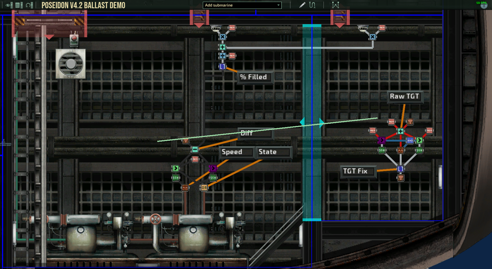
So this is a ballast tank (ignore the components and displays for now).
The normal way that a ballast tank is used for buoyancy control is by plugging the Navigation Terminal’s y velocity output into each pump’s target level. What the Nav Terminal outputs is a number that the pump would then add to 50 to get the ballast level. So if the Nav Terminal calls for ballast tanks to be 50% full, it outputs a 0. If plugged into the target level, the pump will fill the room to 50% with water. Here’s why that doesn’t work with non-rectangular ballast tanks (still ignore the components and displays for now, that’s the next section):
The green line drawn on the left, larger hull is halfway up the hull’s height. The green line on the right, smaller hull is halfway up that hull’s height. Notice that they’re not in-line. If the pumps in the left hull are used like they normally are to fill the room to 50%, they fill their hull up to the green line and the right hull up to the pink line.

This is actually less than 50% of the total room volume though, so this setup will have the sub be lighter than it thinks it is, and could result in it ascending even though its trying to stay neutral. If the pumps were in the right hull, the opposite would happen: that hull fills up to its green line, the left hull also fills up to the height of THAT green line, and the sub is heavier than it thinks it is, and could begin to sink.
The solution: A whole bunch of components
If you look at the screenshot of the whole tank, you’ll notice that the components are split up into 3 sections:
Each of those sections serves a different purpose, and I’ll explain each in-depth below.

The right part is for converting the number that the Navigation Terminal outputs into a percentage of the room that’s supposed to be filled.
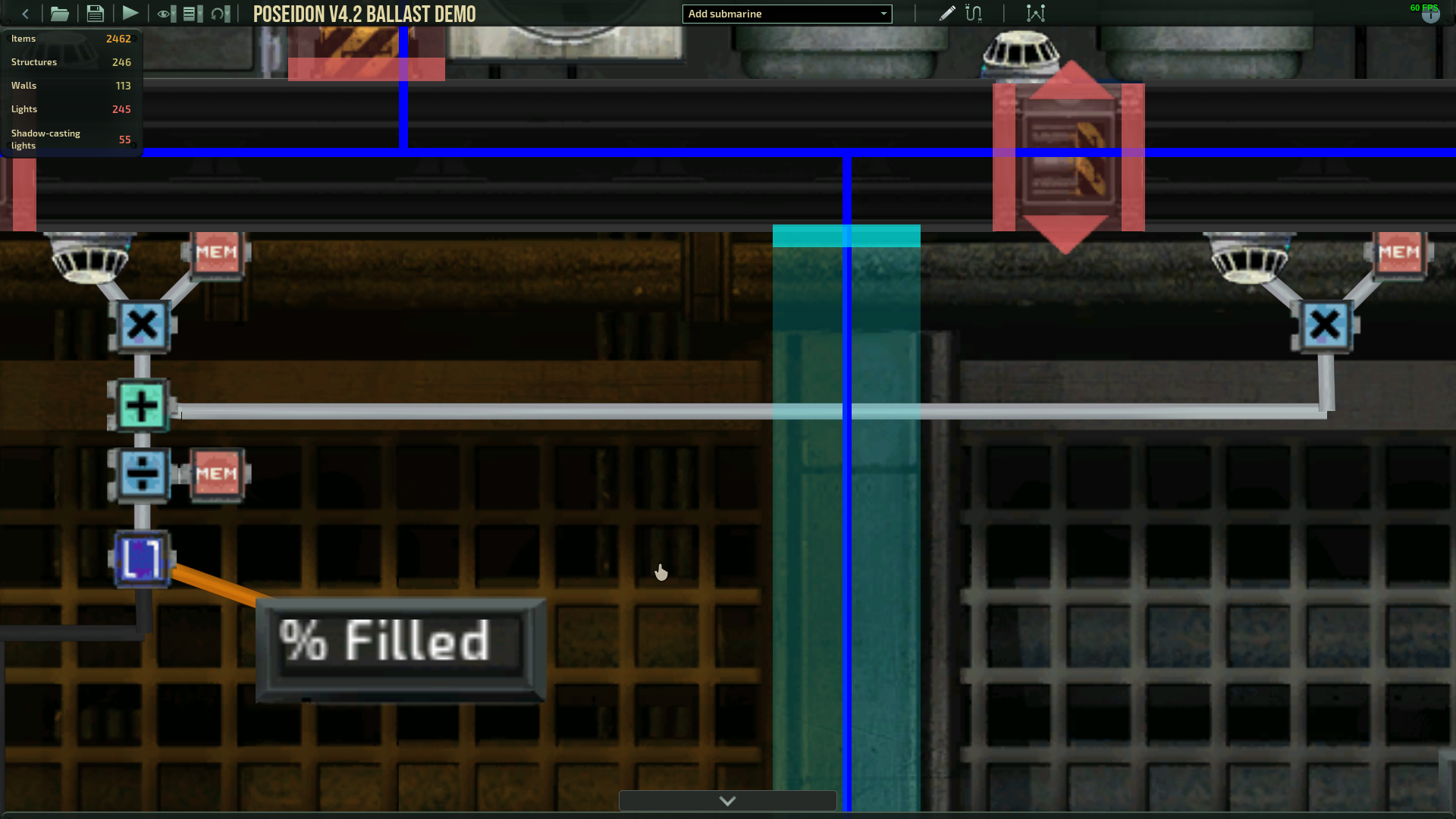
The top part is for calculating the percentage of the room that’s currently filled with water.
The bottom part is for comparing the target and actual numbers and setting the pump settings respectively.
If you want to get hands on with the sub I used in the screenshots, this is the sub with the text displays: [link]
If you don’t care about the text displays here’s a version (the main version) without them: [link]
Right Group: Calculating the Target %
Calculating the percentage of the room that should be full of water is surprisingly difficult. The number that gets output by the Navigation Terminal ranges from [NBL-100,NBL+100] where NBL is the ship’s neutral ballast level, numbers 0 and below represent an empty tank, and numbers 100 and above represent a full tank. NBL varies by ship and changes based on how much hull is dedicated to ballast tanks and also the total amount of hull volume. NBL is generally near 0, somewhere from -5 to 5. Since we’ll be comparing what the Terminal is requesting to the amount of water in the room, we’ll need to adjust the number to be between 0 and 100.

First we’ll add the number output by the Navigation Terminal to 50 to get what a pump would normally try to set a room to if connected like normal.
Next we need to determine if the number is lower than 0 or higher than 100. Since the Nav Terminal can output numbers lower than -100 and higher than 100, 50+ that number can be as low as -50 or as high as 150. Obviously the room cannot be -50% or 150% full, so we’ll do what the pump implicitly does and convert negative numbers to 0 and numbers greater than 100 to 100.
The adder combining the Terminal output and static 50 outputs its result to 3 components: the lower side of the left greater than; the upper side of the right greater than; and one of the signal input pins on the relay component.
The greater than components do exactly what I described above: the left one checks to see if “0 > X” and the right one checks to see if “X > 100” where X is the output of the adder component. (!!!IMPORTANT WEIRD QUIRK!!!) They’re both set to output 1 if their condition is NOT met, and 0 if their condition IS met. This is because the relay component that X goes to is only active if both greater thans have their conditions not met, ie if either input to the and component becomes 0 the relay component is disabled.
Both greater thans have a corresponding signal check component, both with a target signal of 0 and a blank false output. The true output for the left one is 0, and the true output for the right one is 100.
Now, if X is 60 (or any other number between 0 and 100), both greater thans are false and 60 is allowed to pass through the relay component. If X is -30 (or any other number less than 0), the left greater than goes true, disabling the relay component and allowing its signal component to output 0. If X is 120 (or any other number greater than 100), the right greater than goes true, disabling the relay component and allowing its signal component to output 100.
Rounding the resulting number (and, in the next section, the calculated current filled percentage) keeps the pumps from flickering on and off to correct for minute, inconsequential differences.
The wifi component could be replaced by a hard wire to each ballast tank using this system, but keep in mind that this value is applicable to every single ballast tank on the ship. This group of components only needs to be on a given ship once, where as the other groups will need to each be done in each tank.
Top Group: Calculating the Current Room State
This section is probably the easiest. We need to figure out how full the room is with water. Water detectors can output the % water level of the “room” they’re in, where room sneakily means hull.
Each hull has a volume that can be found by selecting the hull object in the editor. (!!!IMPORTANT WEIRD QUIRK!!!) This number should be put in a memory component, but be very careful! We’ll be multiplying this number by the % water level output by the water detector in the hull, but that number can be up to 100. The unit that the hull is measured in is very small, so one hull can be well over 100,000 units in size. Multiply and adder components max out at 99,999,999; you’ll need to reduce the size of the constant in the memory component, or most ballast tanks will overflow the components and screw up the calculations. I suggest moving the decimal place over 2 positions (ie a hull of size 20,000 becomes 200.00 in its memory component).
Multiplying the % water level of each hull by its volume weights the percentages so that if one hull is twice as large as another, it factors into the overall percentage of the room being filled twice as much. For example, if I have one hull that’s 100,000 units large and 20% full and another hull that’s 20,000 units large and 80% full, the amount of water in the room is
(20% * 100,000) + (80% * 20,000), or 36,000 units of water.
After summing the results of all these multiply components together, we need to divide by the total hull volume that the ballast tank takes up. (!!!IMPORTANT WEIRD QUIRK!!!) The total volume needs to be offset in the same way that each individual hull volume was. If you moved the decimal point 2 positions for each individual one, you need to move the total volume over by 2 as well (so for the last example, if you made the individual memory components 1000.00 and 200.00, the memory component for the whole room needs to be 1200.00).
Round like we did in the last group.
Remember, this group needs to be done in each tank separately. Chaining together more than 2 hulls just requires an extra detector, memory component, multiply component, and adder per hull. The sub that I linked to in the first part of this guide has an example of a ballast tank split into 5 hulls.
Bottom Group: Comparing the Results and Setting the Pump
Almost done, I promise. Now that we’ve found both the percentage of the tank that we want filled with water and the percentage of the tank that we already have filled with water, we can compare those numbers to find out if the pump should be pumping in, pumping out, or not pumping at all.

The left greater than component checks to see if “D > 0” while the right checks to see if “0 > D” where D is the difference between the target value calculated by the Right Group and the current value calculated by the Top Group.
If D > 0, the Nav Terminal is calling for more water in the tank (ie descending), so the pumps need to start pumping in. If D < 0, the Nav Terminal is calling for less water in the tank (ie ascending), so the pumps need to start pumping water out.
Each greater than has a corresponding signal check component. If the left one is activated, it outputs a value of 100, which is the maximum speed for pumping in. If the right one is activated, it outputs a value of -100, which is the maximum speed for pumping out. Both have blank false outputs.
Those components both go to the set speed input for the ballast pump(s) in the room. I fed them through a relay component just to simplify things.
The values from the greater than components are also used to set the pump state. If either is true (ie the difference D is non-zero and the amount of water in the tank needs to change in some way), the pump is turned on. If neither is true and the water level is fine as-is, the pump is turned off.
The Small Catches
Congratulations, you’re now an expert in making non-rectangular ballast tanks. I’m sorry if this guide blows up and subs with suggestively shaped tanks become popular.
There’s a catch with making tanks like this:
The ballast tanks are supposed to spawn in at the beginning of each round with a neutral amount of water in them so the sub neither sinks nor floats. However, only the hulls that have pumps in them will do that. If you load in with the power off (as my demo sub does after leaving a station in a campaign) the tanks will NOT have a neutral amount of water in them, and will ascend by themselves. Powering on the sub will have the pumps start correcting themselves.
Also, there’s a possibility that in smaller tanks, values that should be near something .5 (30.5, 45.5, etc) won’t be able to hold. This is probably due to the pump removing enough water to put the water level in the tank a rounded 1% under the target, and turn the pumps back on. The tank will then fill to a rounded 1% over the target before the pump state is updated to off, and then it loops forever. If this happens, the best course of action for an irregular tank would be to change the values in the last 2 signal components to be closer to 0. Try making them 70 and -70, and push them down if the problem persists. (Thanks to ignomen for bring this to my attention on the Discord server)
If you have questions or suggestions, feel free to leave a comment below, or @Joey5729 on the barotrauma discord.