Overview
I have played a lot of in-game editor maps and I see a lot of misuse of links represented by antlines, symbols, or hiding, when using BEEmod’s triggers and logic gates. This guide will aim to fix that so that your chamber comes out a lot cleaner and will probably teach you how to use logic gates. It also includes using other BEE2 items and positioning their links. This guide is only a small part of the main guide, that wildgoosespeeder made about links positioning, so you should check his guide out first: http://steamcommunity.com/sharedfiles/filedetails?id=292356592 Applies to Portal 2, Aperture Tag and Thinking With Time Machine.
Downloads
BEEmod: [link]
BEE2: [link]
TeamSpen 210’s BEE2 additions:
[link]
Trigger once
You use trigger once in these two cases: after entering a chamber to trigger something you need triggered at the start of the test (for example autoportals), or when you want to surprise the player by opening a panel underneath them, or something of that sort. And in both cases you should ALWAYS hide connections! Wildgoosespeeder wrote in his guide that you should hide connections 2% of the time, but when it comes to BEE’s triggers, those percentages rise up to 100. Trigger links represented by antlines/symbols are ugly and unnecessary.
Opening two autoportals at the start of a test in Aperture Tag

Trigger multiple
The same goes here – NEVER connect trigger multiples to other objects through antlines or symbols! Trigger multiple is used rarely:
1) in complicated systems of connections, which I’m not going to talk about, to trigger test elements on and off in a specific order:
A complicated system of connections to open and close autoportals in a specific order in one of my Aperture Tag tests

2) when the player gets stuck in a level in even rarer cases (even the example in the picture isn’t that good, but I can’t think of more situatinons when you need trigger multiples):
If the player falls down in that pit, a flip panel will open. The player will shoot a portal there and as soon as he goes through it, the panel will close.

In the second case, the player should notice the escape panel from any point of the trapped room/place, which means there has to be a trigger multiple everywhere there.
As soon as you cover everything with trigger multiples, simply connect them to a logic gate “OR” (yes, I didn’t say anything about how to use logic gates, but we’ll get to that in a moment). Connect the logic gate to the escape hatch (door, angled panel, or in this case – to the flip panel) and make sure you change the connection visibility of the logic gate to NONE!


Opening/closing doors via triggers
Let it be noted, that in the next lines every time a trigger gets connected to something, the connection visibility has to be changed immediately to NONE. I won’t mention that anymore though, because it should be pretty obvious by now.
Doors usually are the connection between two rooms. So, some people connect a trigger multiple to a door which is right next to it, so that the player has to walk right in front of the door in order to open it, to pass it and then the door closes right behind his back.
While this might be a fine way to open chamber-connecting doors, I think it’s not. I, at least, can get close to that door (but not in front of it, where the trigger is) and still wonder what opens it.
There are also people who place a door in the middle of a trigger multiple and expect the player to go in the trigger, open the door, go through it and as soon as they’re out of the trigger area the door can close. But, if the player wants to, he could return to the first room by going inside the trigger on the other side of the door and opening it from there.
That’s ok and all, but the reason I don’t use that mechanism is because IT’S USELESS. If the player should be able to move freely from the first to the second room and from the second to the first room, why should there even be a door there? If there’s no door on that place the test would be exactly the same.


The better way to make a chamber-connecting door is to connect it to a trigger once and click “start open” in the door’s properties.
If there’s something the player shouldn’t see behind that door (e.g. portalable surfaces) or if there are items/elements, which must not pass the door (e.g. cubes), then place a fizzler behind or in front of the door.
Even the exit door shouldn’t be connected to a trigger in front of it, just so it can be opened when the player steps on the area in front of the door.
If there’s no reason not to make a door (including the exit door) start open, do that!


What is a logic gate “AND”
The “AND” gate is created for test elements which are being triggered by multiple things. However, when you connect multiple activators (e.g. floor buttons) to something (e.g. a laser) the game automatically knows that you want the laser to be triggered only when both buttons are pressed. Therefore, the two ways to connect items, shown in the picture are absolutely the same.
So the only deference is that in-game the logic gate looks ugly?
Yes, kind of, but in my opinion the “AND” gate serves a perfect job as an antline repositioning tool.


This guide will get too long if I include all the ways you can use the “AND” gate, so I made a whole new tutorial describing the possibilities of making your maps better by using “AND” gates. Check it out, you might learn something new and interesting:
[link]
What is a logic gate “OR”
As I said above, when you connect multiple activators to something the game automatically knows that you want that thing to be triggered only when both activators are activated. However, sometimes you need that thing to be triggered by only one of the couple of activators, connected to it. As an example I’ll use floor buttons and the exit door. In this case you only have to connect the logic gate to all of the buttons and to the exit:
Now, no matter which one of the buttons is pressed, the door opens when you press any of them:


How to use a logic gate “OR”
As you can see in the screenshot, the “OR” gate makes antlines look a bit messy, so to fix that just hide the connections of the exit and place the gate onto it. That way it’ll look as if there’s no logic gate there:

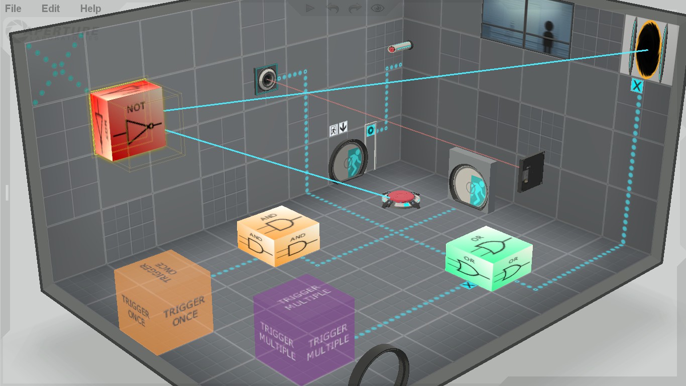
What is and how to use a logic gate ”NOT”
You use the “NOT” gate when you have something that is allready turned on and you want to turn it off.
For example: you place a trigger once at the start of the map and connect it to a door. Then you place a button and connect it to the not gate, which you also connect to the door.
That way when you press the button the door will close. You only have to change the connection visibility of the activator, in this case – the button, to “none” and place the logic gate over it.
(That wouldn’t happen if you just connect the door to the trigger and to the button, because that way the game will think that you want the player to go through the trigger and press the button to open the door.)


And speaking of BEE doors,
Don’t do anything like this:
It looks ugly. To correct this just put some light strips and maybe a logic gate “AND”. I’m not going to explain much.

Another example of using a “NOT” gate
If I want a door to open when a button gets pressed and a laser catcher gets deactivated at the same time:
I connect a button to the door. Then I connect the laser catcher which is on the way of the laser to a “NOT” gate. The “NOT” gate I connect to the door and there we have it – the door will open when the catcher gets deactivated and the button gets pressed at the same time.
All I need to do now is to set the connection visibility of the catcher to “none” and place the logic gate over it.
(This won’t work if I just set the door to start open and connect it to the catcher, because the door would open only when the laser gets stopped, without needing to press the button.)


TeamSpen 210’s antline router
TeamSpen 210 made added some amazing new stuff to BEE2. This guide is focused on the Items, which can help you position your links better and his additions have 2 of them – the antline router and the antline magnet.
The antline router is the same as an undeployed planel, only – it’s cheaper and it doesn’t require space behind it. It can be used to manipulate the path of the antlines. So instead of going straight from the activator to the activated item, the antline’s path can be changed like this:
Of course, you must place a lot of antline routers to make these curvy antlines:


TeamSpen 210’s antline magnet
This element can be used more or less the same way as the logic gate “AND”. It can change the course of the antlines which are connected to one element. With this magnet the antline links can end wherever you want near the activated item:
On the left,…
…on the right,…
…above,…
…or below it.
Of course, you have to make the connection visibility of the activated item invisible first (just like the “AND” gate)
But be careful, because connecting multiple activators to one item can get a bit messy and ugly, so try not to do something like this:


Conclusion
With these examples I provided, expect a little to a lot of trial-and-error experimentation getting your antlines just right. Your chambers should be a lot cleaner and your test subjects will thank you for it!
I really did copy-paste some sentences from Wildgoosespeeder’s guide, which inspired me to make my own and which you should definitely check out:
[link]
Happy map making! If you have further suggestions, don’t be afraid to send a comment my way! If I find the antline tip useful, I will put it in the guide!