![Multiple Inputs (Logic Gates) [outdated] for Scrap Mechanic](https://steamsolo.com/wp-content/uploads/2021/07/multiple-inputs-logic-gates-outdated-scrap-mechanic.jpg)
Overview
Learn how to build an easy, compact, fast and multi-use logic gate step-by-step![outdated with the release of proper logic gates into the game]
How it works
Welcome to my guide! If you already know how logic gates and Scrap Mechanics’ parts work, you can skip this section. If not, let me give you the short version.
You might also wanna check made by Jack The Sp00ky:
The purpose here is to have a machine that makes a simple decision based on it’s inputs and outputs it to something. Let’s try to explain by example:
I have 2 buttons and I want either of them to turn on a light as long as they are held. For that, I could use an OR Gate. If neither of the buttons are being held, the light remains off. If any or both are on, the light will also be on.
Ok, that sounds simple enough, and it is. But the key here is that there are many other ways to make decisions in many other situations. There are, in total, 7 gates, and a few them are as simple as the OR Gate I just talked about. The AND Gate, for example, will only turn on if both it’s inputs are on, and only as long as that’s so. For the complete list, visit the Logic Table section at the end of this guide.
Here we’re using rotating blocks to manipulate a Sensor’s state. The way this works is very simple:
The sensor will look for any object in front of it that doesn’t belong to the same object it’s attached at. This makes it so that the block stuck to the floor in front of it blocks the sensor without triggering it (and therefore allows you to walk in front of it without disrupting anything).
The rotating blocks will go in front of the sensor in order to trigger it and go away in order to turn it off.
The controllers will manipulate the 2 bearings, allowing the rotating blocks to do their job (as stated above).
With that in mind, we set the controllers to specific Default and Switch rotation settings (depending on which gate we’re building, as explained in the Logic Gates section of this guide), making the blocks go in front of the sensor or out of it depending on the inputs the controllers are receiving.
I believe after building and testing it you’ll be able to understand it a lot better. If you still have doubts, feel free and encouraged to ask me anything in the comments below, and I’ll gladly respond and update the guide as needed.
Without any more delays, let’s build it already! 😀
Building the machine
1) Start with a 4×3 floor. (if you’re building in your house or any other construction, you can skip that part, just remember you’re gonna need that uninterrupted space)

2) Now add 2 blocks on the top-left corner. (Which blocks you’re using make no difference, and that applies for the whole machine)

3) Now add a sensor on the top-middle.

4) And we’re gonna need 2 controllers.

5) Now 2 stacked blocks on the bottom-middle.

5b) Showing a different angle.

6) Add a bearing to the top-left block facing downwards.

7) Add a block to that bearing.

8) Repeat (add another bearing and another block).

9) Add another block on top of the last placed one.

10) Machine construction is done.

10b) Another angle.

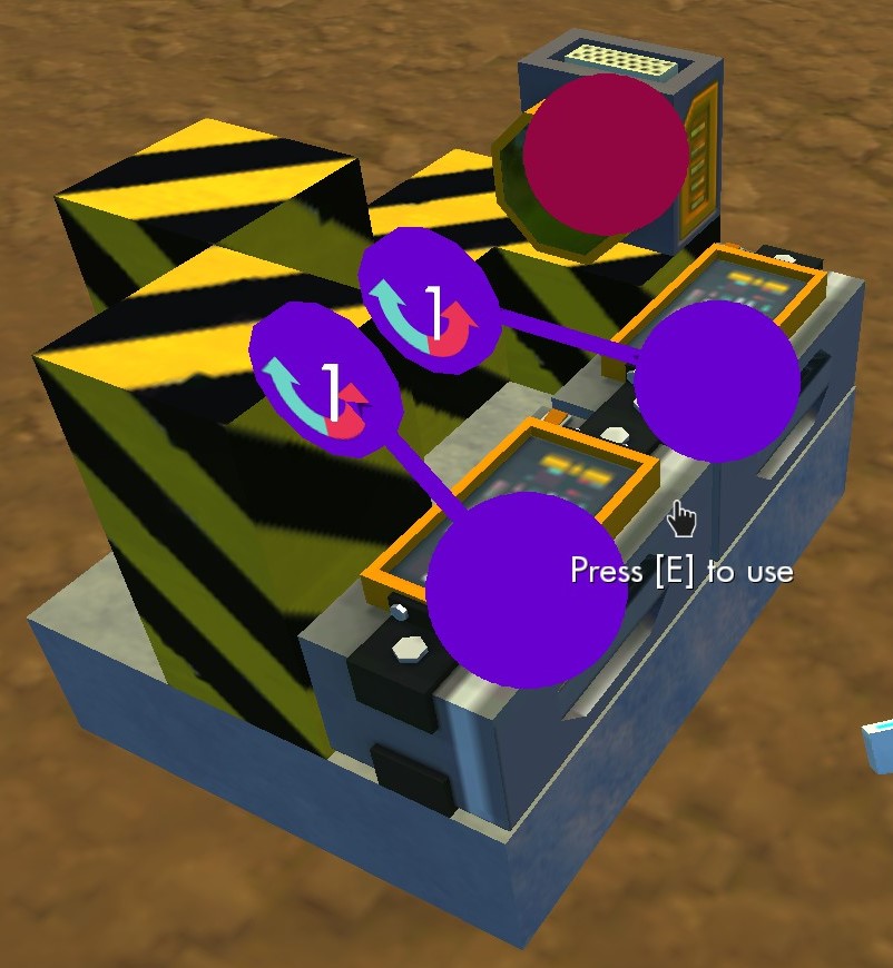
11) Link each controler to it’s closest bearing.
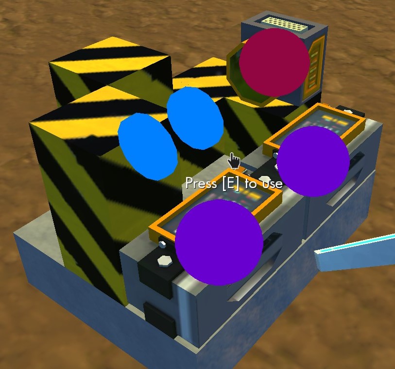
11b) Like this.
Logic Gates
So now we open each controller (by pressing E) and see this interface. Depending on what gate we’re creating, the values here will be different, but that’s all that’s gonna change.

So for every gate both controllers must have the same setting, and it will always be as simple as one default value (at the gray circle) and one switch value (at the first white circle).
In order to use the gate, just connect each input (like a switch) to either controller and connect the sensor to the object you want to manipulate.
Applications (When to use each gate)
If you already know how to use logic gates, you can skip this section. For those who don’t, here’s a simple list on the uses of each gate. Just connect each switch to either of the controllers and use the sensor to activate the object you want.
- Opening a door from either side: XOR
- Deactivating a sensor with a switch: AND
- 2 players must each be holding a button at the same time: AND
- Either of 2 switches activate the same thing: OR
Please feel free to suggest more uses in the comments below and I’ll add them here asap 😀
Logic Table
Not Gate
The Not Gate, however, takes only a single input, and though you still COULD use the machine above for it, you can save space and resources by building it simpler:

Now just follow this settings and it’ll invert the input (as expected from a Not Gate)

Flip Flop (Extra)
As requested, here’s how to build a Flip Flop:
(alternates between on and off when and only when it takes an input. It’s just like how the switches work, but instead of someone pressing it’ll take an input from somewhere else, like a button)
1) Start with a 3×3 block

2) Add 2 stacked blocks on the top middle and one on the top right

3) Add a sensor on top of the top-right block

4) Add a controller sidways on the bottom left corner

5) Add a bearing facing you on the top block of the top middle stack

6) Connect the bearing to the controller (to prevent it from rotating after step 9)

7) Add a block to the bearing

8) Add a block to the left of the one you just placed

9) Now one to the right

10) Finally put 2 stacked blocks on the bottom right corner to block the sensor

11) And now we can edit the controller

12) Skip the default angle (gray) and set the first angle to +90º. You’ll also need to click the “Cycle” button on the bottom left of the Rotation Editor window.

Now link a button (or some other timed input) to the controller and voilà. Do notice, however, that the button has to be held for about half a second for the machine to switch states, otherwise it will undo the last change. You’ll understand it (and get the exact timing) when you try it out.
Latch Gate
This gate is a bit unlike the others but can still prove itself quite useful. What it does is keep the input from A until B is pressed. If you’re not familiar with this, then you probably don’t need it. But if you want to learn it anyway, allow me to explain:
You have 2 buttons. At first, the gate is OFF.
A is the input button. B is the reset button.
If you press A, the gate goes ON.
If you press A again, the gate stays ON.
If you press B, the gate goes OFF (resets).
If you press B, the gate stays OFF.
So in a way, you can say A is the “turn on” input, and B is the “turn off” input, and one will never do the other’s job.
How’s this useful? Well, it’s more often used for some more advanced logic, but as long as you keep in mind that you have this option, you’ll know when you need it.
(to be updated in a couple hours)
Compact (2×3 +1)
In case you feel the need for an even more compact version, here it is!
(I say it’s size is 2×3 +1 because each gate only takes 2×3, but at the end you need a wall to stop the last sensor from getting disturbed)


FAQ
The gate has 2 controllers and a sensor. Connect each switch of your project to each controller on the gate, those are the inputs. Then, connect the sensor to the objects you want to be activated.
Check the “Applications (When to use each gate)” section of the guide. You can easily find it on the (right) side menu, under Guide Index.
Add me as a friend, I’ll gladly show you in-game how it works. 😀
Of course! Let’s all be friends! 😀
Thank you
Thank you for reading my guide! Hope it was as useful as intended! 😀
Please remember to rate it accordingly 😀
If you have anything to add or any kind of suggestions, you’re more than welcome to comment below! May the scraps be with your mechanics.