Overview
Do you want to do something like switch between different video screens with the push of a button? Do you want to use buttons to select a radio frequency instead of typing a number in with a keypad? Maybe you just want to know how to use a specific logic block? Do you need to know what math and calculations you need to make a certain type of system? You might have seen something unique on the workshop, but you don’t actually know the basics of how to start making that type of system. You may have even seen a tutorial video online but didn’t quite understand it because you’re not at that level yet. I want to demonstrate some of the small tricks that I use in most of my logic circuits. Granted, I don’t make anything too crazy or complicated, but these small tricks serve as a base on which to build other types of systems.
Introduction
There are many functions in Stormworks that have not always been clearly explained. I started with no knowledge of using logic in my creations and not being able to write a single line of code in a LUA block. Over time, I started learning new things, mostly through trial and error. I started using radios to communicate between vehicles, but I had to manually type in radio frequencies using a keypad. I built my first navigation system using radio transmitters to send and receive grid coordinates between vehicles and navigate the vehicles closer together by comparing their grid coordinates. This system just used the Pythagorean Theorem and a little algebra to calculate the linear distance between the two vehicles. I set the transmit and receive frequencies for the system by entering them in with a large keypad. Later on, I learned how to calculate the bearing to the tracked target using trigonometry and some more advanced algebra. I then decided that I didn’t want to use the keypad anymore to select frequencies and instead I wanted to use instrument panels, arrow buttons, and seven segment displays. I had to learn how to do that and it was a frustrating process when I first started out. Now I can cycle between hundreds of frequencies with the push of a button and I even started making touch screen monitors and digital displays. My goal with making this guide is to put all of the little things I’ve learned into one location and maybe someone else can learn through my trial-and-error process of figuring out more advanced processes in the game.
Understanding Logic Gates
There are multiple kinds of logic gates used in Stormworks and they each serve a very specific purpose. You might be wondering what is a logic gate and how can it be used? To put it simply, logic gates work using binary 1’s and 0’s and they activate if their specific conditions are met. They are used mostly in digital electronics, but they can also be used in analog electronics. Although, using logic in analog circuits requires manipulating the chemistry of a device, mechanical threshold, or sensor in order to detect changes in voltage, resistance, pressure, or something of that nature as opposed to just detecting a binary signal.
OR Logic
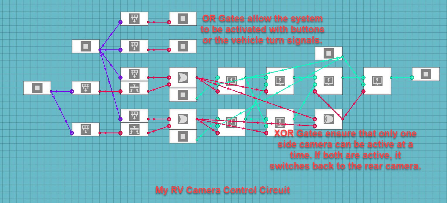
One of the most common and easiest gates to use, in my opinion, would be the OR Gate. It can be activated if either of its inputs are activated. It outputs a binary 1 if either or both of its inputs are a binary 1. I use OR Gates on many circuits and for many things. A common use for an OR Gate would be to make it so that something can be activated by two different input sources. For example: my RV camera system uses OR Gates to activate the side cameras with either the push of a button or the turn signals on the vehicle.

XOR Logic
OR Gates are nice but what if you didn’t want something to happen in the event of both input signals being activated? In this case you would use an Exclusive OR Gate or an XOR Gate. This says that the output will be active if one or the other input is active, but if both are active then the output will be inactive. I also used this gate in my RV camera system to make sure that my side cameras can only be activated one at a time. In the event that both are active, they turn off and the monitor returns to the rear camera display.


Not Logic
Not Logic Gates are used to output the opposite of the binary input. If the input is active, the output is inactive. If the input is inactive, the output is active. You can use Not Logic to make something active by default if you’re using an instrument panel instead of a toggle button. One example of how I use Not Gates would be the emergency light system that I put into my fire engine and other emergency vehicles. It uses a Not Gate to ensure that only one set of lights are active at a time.

NOR Logic


Not OR Logic Gates are similar to OR Gates except that instead of the gate requiring at least one input to be active for the output to be active, the gate requires at least one input to be inactive for the output to be active. Both input signals can be inactive and the output will be active. There is such a thing as an Exclusive NOR or XNOR Logic Gate, but that does not appear to be in the game. I have not used one of these yet, so I don’t have any functioning examples of it.

AND Logic
AND Logic Gates state that both input signals must be active for the output signal to be active. These are useful for systems that you don’t want active unless all of the conditions are met. For example: I made a series of air-drop supply crates that are activated by a vertical speed sensor. I use an AND Gate to make sure that my parachute only deploys when I arm and drop the crate. Without the gate, the parachute would deploy in the plane during takeoff and that would waste the parachute.

NAND Logic


Not AND Logic Gates are similar to AND Logic Gates in the sense that both input signals must be in the same state. The NAND Gate states that both input signals must be inactive for the output to be active. This is another logic gate that I have not used yet and I don’t have a functioning example of it.

Simulating “On By Default” Using Logic
This is something that took me a lot longer than I like to figure out. It is fairly useful that toggle buttons in the game can be set to “On by Default” using their settings in the editor. This is very useful for me because it allows me to mount helicopters on ships using large magnets and have them already attached when the ship spawns in. For the longest time, my magnets had to have a full-size toggle button in order to have the “On by Default” functionality needed for the ship to spawn safely and properly. You may have noticed that instrument panels do not currently have the ability to alter the state of toggle buttons and switches by default. I learned that you can simulate this function in your micro-controller using logic gates. Say that you have an input from a switch on an instrument panel that you want on when the vehicle spawns. You can accomplish this by using a Not Logic Gate in the micro-controller. In the last section, I told you how a Not Gate works and how it can be used, but I did not adequately explain what else it can be used for. I said that the Not Gate outputs the opposite of its input and that can be used to turn something on. You simply connect the Not Gate to the input on/off signal that you want active by default. Once the creation spawns in, all switches are off by default and a binary 0 outputs a binary 1 through the not gate. This simulates the “On by Default” function given to full-size toggle buttons. I use this trick to set all of the parking/wheel brakes on all of my aircraft and land vehicles. I also use it to have nose-wheel-steering enabled by default on all of my planes. This simple logic trick allows you to add more functionality to your instrument panels that control sensitive things that need to be on when the vehicle spawns.

Using Threshold Gates and Comparison Functions to Automate Processes
Another useful thing to know is how to use number input signals to activate other systems that require on/off input signals. You may want to create an automatic transmission micro-controller, activate a parachute over a certain speed, or maybe even balance fuel between two separate fuel tanks so the weight stays even on the vehicle. All of these things can be accomplished by using a combination of Threshold Gates, Greater Than Functions, or Less Than Functions. These functions can also be used to convert a number input to an on/off signal.
Threshold Gates
Threshold Gates are used to tell if an input number value is within a set limit. If the value is within that predetermined limit, it outputs a binary 1 to activate another system. I use these for a lot of things like resetting counters, switching gears with gearboxes, and activating my parachute drop system. You connect an input number to the number input, set the range on the gate for the range you want something to happen within, and then you connect the output to whatever process requires an on/off signal to activate.

Greater Than Logic
Greater Than Logic Gates are used to compare two input numbers. The gate outputs a binary 1 in the event that the first number is higher than the other. You could have a number input that you want something to activate when that number passes a set-point. You would use a constant number as the second number that you want the input number compared to. I use this gate in my fuel balancing system for aircraft. I have two different fluid meters connected to circuits measuring their percent-fill-capacity and these two values are put into two greater than logic circuits. If the left tank is higher than the right tank, a pump is activated pushing fuel to the right tank. If the right tank is higher than the left tank, a different pump is activated pushing fuel to the left tank. These can also be useful for activating a warning light if your vehicle gets above a certain speed or engine temperature.

Less Than Logic
Less Than Logic Gates are similar to Greater Than Gates in the sense that they compare two number input values, but this time they are checking to see if the first number is lower than the other number. You would use a constant number for the second value that you want to compare the input number to. I use these gates in my fuel control circuit where a light is activated if either tank falls below 20% fuel capacity. I also use this system in my weather warning system to activate an alarm if the outside temperature falls below 0 Degrees Celsius. These can be used for any purpose in which you want to be aware if a system falls below a set-point.

Using Buttons to Change Values on a Seven Segment Display
This was the first thing that I thought was slightly more advanced that I really wanted to learn in order to make my radios and radio-based equipment look better and more professional. My goal was to show a number on the seven segment display, have that number be a frequency for a radio of some kind, and be able to change that frequency using arrow buttons on an instrument panel. It turns out that doing this is not as hard as I initially thought.
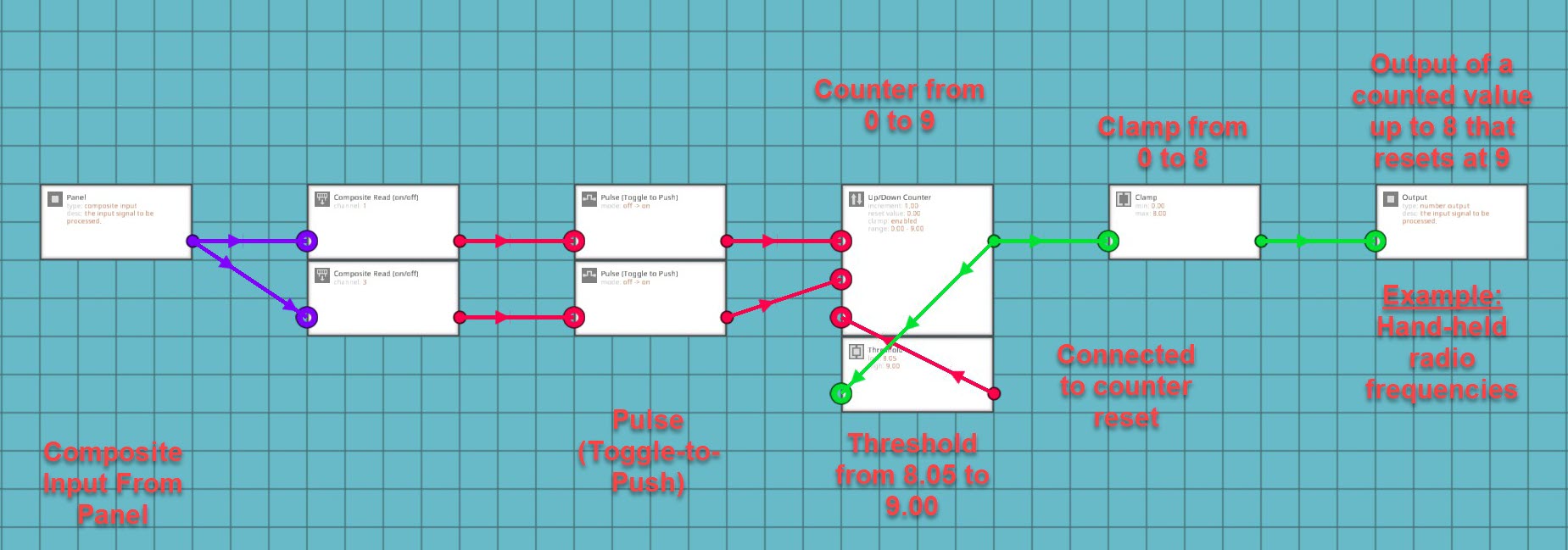
I was attempting to just connect the composite on/off signal to an up/down counter and it wasn’t working. I learned that if you just connect a push button to the counter with nothing in between the button and the counter, the counter treats it like you’re holding the button instead of just pushing it. This meant that the counter was giving me random numbers instead of simply going up and down within the set range of the counter. I found out that the trick to making it output a usable number was to have the composite-read-on/off connected to a toggle-to-push (Pulse) logic block and connect that to the counter. This gives the counter a stabilized input that it can actually use to increase or decrease the counter as required. Remember to set the button on your instrument panel to push and not to toggle. Personally, I use arrow buttons to represent increasing or decreasing the counter.
Remember to set the clamp in the counter otherwise it just increases infinitely. I later found out that you can add a threshold gate to the output, increase the clamp to one number higher than you want the display to show, set the threshold gate to half of a number higher than your determined max shown value and connect that back to the reset node for the counter.


If you’re using a digital display through the LUA block, it might be useful to add a clamp to the output of the counter so that it doesn’t flash with the reset number before resetting the counter. It sounds like a trivial problem, but my integrated navigation system uses the LUA script to digitally show all of the values from all sub-systems included in the main system. These values are spaced out and need to stay within a set area or the system doesn’t look right for me. Both navigation systems in the system use 100 radio frequencies to operate ranging from 0 to 99. I have the threshold gate set to reset the counter at 100 back down to 0. I put a clamp on the output so that the screen does not show 100 as the frequency, since 100 does not really fit in my display system. The frequency doesn’t stay at 100 and it would only flash for a split second before switching to 0. I decided that I didn’t want the system to show the 100 so I clamped the output from 0 to 99. Systems using seven segment displays don’t need this clamp, but it’s still a fairly useful trick if you’re like me and don’t like arbitrary numbers that don’t mean anything flashing on your displays.
This setup is useful if you want to select radio frequencies using buttons and not a keypad. It is also useful for using buttons to zoom in and out on a map display. Connect the output from the clamp attached to the counter to the number input setting the zoom level on your LUA script for your map. This can also be used with touch screen controls. In that case, the composite input will come from your LUA script on the channel for your button on the display.


Using a Counter and Buttons to Change Displays on a Monitor
One of the systems that I recently decided to make has five different screens that can all be shown on the same monitor. I used a system of OR and XOR logic to select the different screens and return back to the root screen. I just found out that there is a much better way to do this that is not as complicated or confusing of a system.
One thing that you can do is to use a counter, two buttons (either analog, digital, or touch screen), and toggle-to-push (pulse) blocks. Say you have five different video displays or menus that you want on the same monitor. Place 4 video switch-boxes in a row. Decide which screen you want to be the “Root” menu or screen and connect that video input or LUA script to the off terminal on the first switch-box. Then go down the chain of switch-boxes and put the output of the previous box into the off terminal of the next box. Get the video input signals or LUA scripts for the consecutive monitor screens connected to the on terminals of the switch-boxes in the order that you want them to be activated in. Now setup a counter circuit just like you did for the radio in the last part of the guide. Use a composite channel or on/off input connected to a toggle-to-push (pulse) logic block and connect those to the the up and down terminals of the counter. Set the clamp on the counter from 0 to 5 and then connect a threshold gate to the output of the counter. Set the threshold gate from 4.05 to 5.00 and connect the output to the reset terminal on the counter. Now grab 4 more threshold gates and place them near the video switch-boxes. Set the first gate from 1 to 1 and connect the output to the switch input for the first switch-box. Set the second gate from 2 to 2 and connect it to the second switch-box. Repeat this process for the remaining threshold gates and consecutive switch boxes. Now you should be able to toggle the counter up and down while simultaneously switching between different monitor screens.
The alternative is much harder to explain and it was not a very good system to use for five separate screens. It did work for my Motorhome RV Camera system though. It only has three camera feeds connected to the controls on the console and the turn signals for the truck. Basically, you have the rear camera as the default or root screen, the side cameras can be activated with either a button on the console or the circuit for the turn signals, the side cameras are connected to an Exclusive OR (XOR) logic gate which makes it so that if both buttons are pressed the monitor returns to the root screen. It means that an XOR gate says that one or the other option can be on and the system will be on, but if both options are on the system will be off. It is much harder to scale this system up to more screens and it led to confusing results on one of my hardest systems to make.


Using Seven Segment Displays to Show Larger Numbers
Say that you want to upgrade your newly created radio system from the ten frequency system between zero and nine. Instead of ten frequencies, what if you wanted to use one-hundred frequencies or even a thousand of them. Doing this is a lot easier than you might realize. Obviously the seven segment displays can only show numbers between 0 and 9, but if you use multiple displays together you can expand to hundreds and thousands of different numbers.
This is accomplished by using a function on the number that you want to use and breaking it down into individual digits that make up the number. The function that you will use will be:
One’s Position:
floor(x/1)%10
Ten’s Position:
floor(x/10)%10
Hundred’s Position:
floor(x/100)%10
Thousand’s Position:
floor(x/1000)%10
You might be wondering what these equations actually mean. It’s actually quite simple. “Floor(x)” will take your x input and round it down to the nearest whole number. It always rounds down regardless of what the actual decimal is. The “X/1” takes the the x input and finds out how many times it can be divided by 1. The number will obviously be higher than 1 but this will give you the last digit in your larger number. The “%10” added after the floor function is a modulo number in which it divides the input number and outputs the remainder. Each of these equations are applied to the same input number and then the outputs of the functions are added to composite channels corresponding with the displays on your instrument panel. For example: you have four seven-segment displays in a row on two separate instrument panels on channels 1, 2, 5, and 6. The thousand’s function will go to channel 1, the hundred’s function will go to channel 2, the ten’s function will go to channel 5, and the finally the one’s function will go to channel 6. This will allow you to show numbers from 0 to 9999 on a seven segment display. You don’t always need to show 10,000 numbers on your displays so only use the number of position equations that you actually need. Additionally, you can add more equations in intervals of powers of ten to make the display bigger than four digits.

These calculations are useful if you want to display more than single digit numbers using seven-segment displays. You can now display as many digits as you want to make displays for. It also can be applied to digital displays as well. In that case, put the composite numbers into a LUA script and recall the value on that channel to a specific place on the screen. I did this for my integrated navigation system to display the digital clock on all five screens. Separate big numbers into individual digits using these equations and put each digit on the channel of your chosen display. If you do it properly, the numbers should be displayed in order on your display system.


Using a Compass Sensor to Calculate the Current Heading for Your Vehicle
You may have used the compass sensor on one of your vehicles, but you don’t know how to incorporate the data from the sensor into anything useful. You may have noticed the sensor outputs the turn that must be made in order to face North. This information does not seem overly useful. What if I wanted to know the heading out of 360 degrees, like the one shown on a magnetic compass? It turns out that this is a fairly simple calculation.
First you need to convert from the strange decimal number to degrees. This is done by using the following calculation:
((1-x) * 360)%360
You may have noticed that this equation has another modulo function in it. This equation means that you are subtracting the input number from the compass sensor, multiplying the difference by 360 degrees, and then performing a modulo function to output the remainder from dividing by 360 degrees. This is all that is required to convert the seemingly arbitrary number shown by the sensor into an easier to understand number you can verify with the hand-held compass. It is very important to note that the compass sensor must be placed flat, with the face pointing up and the compass arrow pointing forward on the vehicle. If it is pointing the wrong way, the calculated heading will be wrong.

Another cool thing that you can do with a similar equation is to take the direction number from a wind sensor and use an inverse function to show the direction the wind is coming from on a radial-segmented display. To do that, use the following equation:
((1+x) * 360)%360
Use this equation to determine which direction the wind is coming from. Add 1 instead of subtracting from 1 to determine the direction behind the wind gauge. You can then convert the radial display to use on/off data and threshold gates for the function output in increments of 45 degrees out of 360. 0-45, 46-90, 91-135, 136-180, 181-225, 226-270, 271-315, 315-360. Remember to put the radial display on a higher frequency than the rest of your instrument panel. For my weather system, I put the radial dial on channel 13 because it needs 8 channels to display the incoming wind direction. Also, remember that this equation is used to determine which way the wind is coming from, if you want to know which way it’s blowing, just use the first equation for the heading calculations. It was more useful for me to know where the wind is coming from than where it was going so I used a back azimuth for my system.


Determining the Bearing Towards a Tracked Vehicle or Grid Location
You now know how to find your current heading by using a compass sensor and a number display, but what if you want to know the bearing or direction to some other location? Say that you want to make an autopilot system or you want to build a radio navigation system like I did. This is also a fairly simple process.
If you think back to your high school math classes, you might remember the Pythagorean Theorem (a^2 + b^2 = c^2). You will need this equation to find the linear distance to your target or how far away the point you want to reach is. First, you have to find out what A and B are in your equation. You will need a GPS Sensor to determine your current x and y coordinates (X1 and Y1) in the game world. Then take a large keypad and set a waypoint into it using the map menu. Put these coordinates into the keypad. Those coordinates will become the second x and y values. Subtract x1 from x2 and subtract y1 from y2. Plug the x difference into the x node on a three value function block. Plug the y difference into the y node on the function block. Use the following equation to calculate the linear distance to your target or destination:
sqrt((x ^ 2) + (y ^ 2))
You can also use the 8 value function block so you don’t need to separately do the subtraction. Bear in mind that you will still need the subtraction blocks for the next part of this process. The equation for the 8 value function block is as follows:
sqrt(((a – x) ^ 2) + ((b – y) ^ 2))
Now you know the straight line distance to whatever you are tracking or trying to reach. The next thing is to find out the compass bearing to that target or location. This can be used to tell your autopilot system which way the vehicle needs to be pointing to reach the plotted coordinates. I use it to determine the direction to my tracked vehicle transponder systems.
In order to determine the bearing towards your target, you will need the x and y differences between the two vehicles again. This time, you will be plugging these numbers into the x and y nodes of a different function block. The following equation will be used for the second function block:
atan2(x , y) / pi2
This uses an arctangent function to determine the angle to the target in radians. You then take the output from this function and put it into another single value function block with the following equation:
((1 + x) * 360)%360
This will convert your angle from radians to degrees
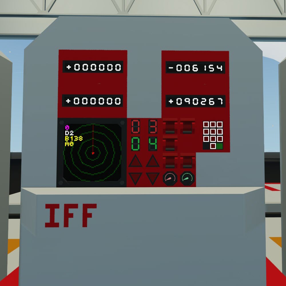
These calculations are useful for getting yourself to a chosen destination or finding a vehicle that you are tracking using something like my TACAN or IFF Transponder Systems.


Using Calculated Bearing to Make a Digital Display or Arrow on a Map
You learned how to calculate the bearing to a target and that can help you start making an autopilot system, but what if you wanted to make an arrow on your map display that shows which way your vehicle is currently heading. Remember that you find your heading by using the equation ((1-x)*360)%360. This outputs your heading in degrees. In order to put it visually on your map display, you will need to convert the number back to radians. This can be done using the following equation:
x * (pi / 180)
Once you convert the angle into radians, connect the output to the composite input for your LUA script. I used the variable b to represent my bearing. In the script I have variables for x, y, zoom, bearing, and the radius of my monitor display. I had to use the following code to draw a line from the center of my display point in the direction of my vehicle’s heading and going out to the radius of the first distance circle on my map:
b = input.getNumber(4)
w = screen.getWidth()
h = screen.getHeight()
r = (w + h) / 4
x1 = (w / 2) + (r / 4) * math.cos(b – 1.57)
y1 = (h / 2) + (r / 4) * math.sin(b – 1.57)
screen.drawLine(w / 2, h / 2, x1, y1)
You might be wondering what all of this means. It’s not nearly as complicated as it looks at the first glance. B is my variable and the number input from the calculated heading that was converted to radians. The screen height and width are the size of the monitor itself. The radius is for a circle that covers the whole screen from top to bottom. X1 and Y1 are using trigonometry to determine which way to draw the line. The first two parts of the equations are telling the program to find the center of the screen and then move away from the center in the direction of the calculated angle. The y portion of the graph in trigonometry is used as sine of the angle or sin(b). The x portion of the graph is used as cosine of the angle or cos(b). You have to subtract 1.57 from each angle because 0 radians starts on the positive x axis while 0 degrees starts on the positive y axis of the graph. 90 degrees converted to radians is pi / 2 radians. Pi divided by two is approximately 1.57. Alternatively, you could use (b – ((math.pi) / 2)) instead of (b – 1.57). This would be more accurate, but it also takes up more space in the script and we have limited space to write code. The line itself has x1 and y1 at the center of the screen (w / 2, h / 2) and x2 and y2 are at the x and y calculated portions of the current facing angle (X1, Y1). This might not have been the best way to label it for this tutorial, but my system does actually work.
This concept can also be applied to building a functioning RADAR Display. Instead of the the angle coming from the compass sensor, the angle would come from the velocity pivot current rotation output. The following equation is used to convert the rotation angle into radians to use the angle to draw a line on the monitor:


(x * (pi / 2))
Once you go into the LUA Script, use the calculated angle in radians to tell the script where to draw the line and which way to make it point. I used an identical code for my RADAR display as I did for my map display. The only real difference is that the RADAR system has the line going to the outer circle on the display so the “R” value is just r and not (r / 4).
These calculations are extremely useful for a wide array of applications. I used similar calculations to make a visual “RADAR” screen for my IFF transponder to draw a dot on a screen in the direction and at a proportional distance from the receiver for a tracked vehicle transponder. These calculations simply need to be adjusted to use different numbers for their variables in the equations. My IFF system uses the “R” value as the target distance divided by the visible range on my display.


Conclusion
I had to learn a lot of these things through hours of trial and error, watching tutorial videos hundreds of times, and simply playing with numbers and math. Hopefully someone finds this information useful or at least somewhat helpful. Maybe you can learn from my experiences and not have to go through the same process to learn all of this.
This is the link to the showcase that I made for all of my avionics systems made using these techniques.
[link]This is the link to all of my radio based equipment in one collection of items.
[link]