Memory Bits 101
Introduction
Since you're interested in knowing how memory bits work, let's first break down what a memory bit even is and what you can do with it.
A memory bit is a component made up of a number of different logic gates that allows you to store data. Think of it as a computer - a very simple one, but still a computer. Every computer operates by storing data as ones and zeros, and that's exactly what a memory bit does too! In the most basic sense, 0 is OFF and 1 is ON, so you can also think of it as a glorified switch.
BUT, a very important difference between a switch and a memory bit is that a switch cannot handle different, automated inputs. Here's what I mean: imagine you want to build a door that closes automatically after a certain amount of time. If you were to use a regular switch, you wouldn't be able to tell the door when it should close on its own. By using a memory bit, you can use a simple button or a sensor as an input to open the door (setting the bit to 1) and a timer as an input to close the door (resetting the bit back to 0).
Multiple memory bits can also be utilized to make complex contraptions that need to store more data (for example, a 7-segment display). These advanced principles will only be mentioned as basic examples, but to fully take advantage of memory bits, you will need to experiment and come up with your own uses.
Making Your First Memory Bit
This guide assumes you're already familiar with how each type of gate (AND, OR, NOR etc.) functions. If you're not, here's a quick recapitulation on what each gate does:
- AND - Active if every connected input is active.
- OR - Active if at least one connected input is active.
- XOR - Active if an odd number of connected inputs is active.
- NAND - Inactive if every connected input is active.
- NOR - Inactive if at least one connected input is active.
- XNOR - Inactive if an odd number of connected inputs is active.
To make a basic memory bit, you only need three gates - two NOR gates and one OR gate wired in a loop, as shown below.
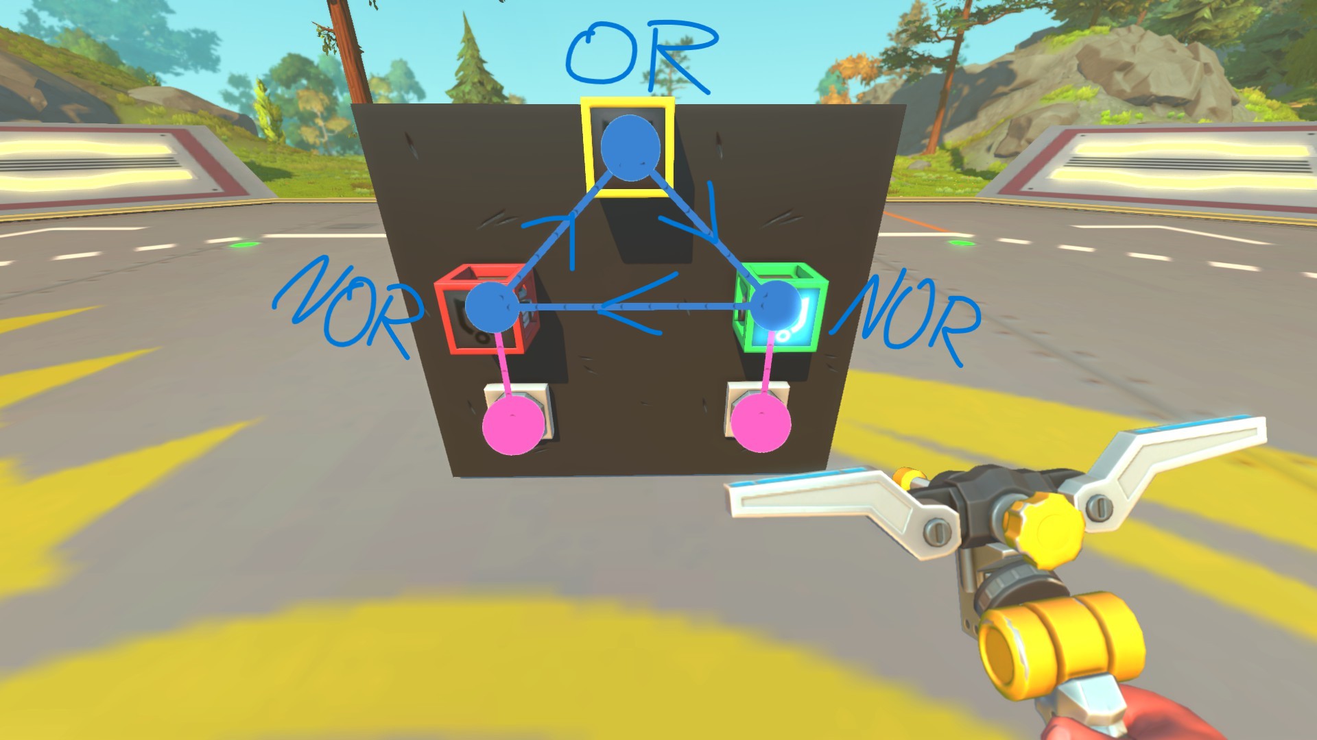
These two NOR gates act as your input gates, and the yellow one (OR) is the output gate (ON/OFF). If you wire two buttons to them, you can change the state of the output by pressing them. Each button is only able to turn it ON or OFF - this is extremely useful because you can have different independent actions influencing the state of the memory circuit. If you try building your memory bit like this, you will notice that it starts glitching (oscillating) either when you give it a 1-tick impulse or right after putting it on a lift. This happens because each gate in Scrap Mechanic introduces a 1-tick output delay, which essentially traps the signal in an infinite loop. To fix this issue, you need to introduce one more logic gate to counter this behavior.
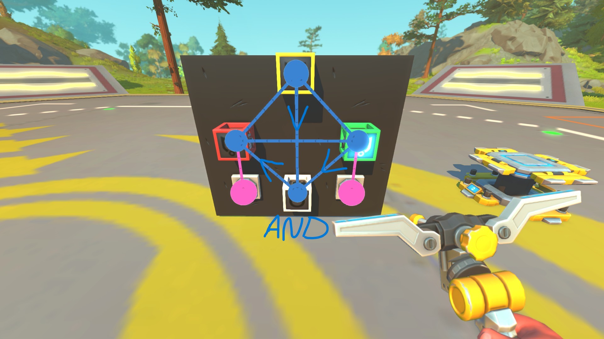
As you can see, the last needed component is an AND gate, wired as shown in the image above. This gate acts as a stabilizer that breaks the infinite loop once it occurs. While it doesn't fully prevent a brief flicker from a 1-tick input, it will successfully stop the endless glitching.
Keep in mind that this flicker will still occur for a split second when updating the creation on a lift or once you give it a short (1-tick) input - this is a known downside of this setup. To counter it, you just need to give the memory bit a slightly longer input pulse (press the button for longer) or introduce a pulse extender.
Still, this specific memory circuit is very practical since it doesn't introduce too much lag to your creations, it's very cost-effective (costing only 4 gates), and it can be fully built in Survival mode without any external tools. Later in this guide, we will look at an advanced memory circuit that eliminates these issues entirely, though it requires blueprint editing and isn't fully survival-friendly.
How to Make Use of Memory Bits
Now that you know how a memory bit functions and how to build one, let's take a look at how exactly you can make use of them.
This exact setup can be easily achieved using a memory bit. You connect the sensor to trigger the memory bit ON, which opens the door. At the same time, the output of the memory bit (OR gate) triggers a timer. This timer will count down your desired amount of time and then send a signal to put the memory bit back into an OFF state, automatically closing the door behind you.
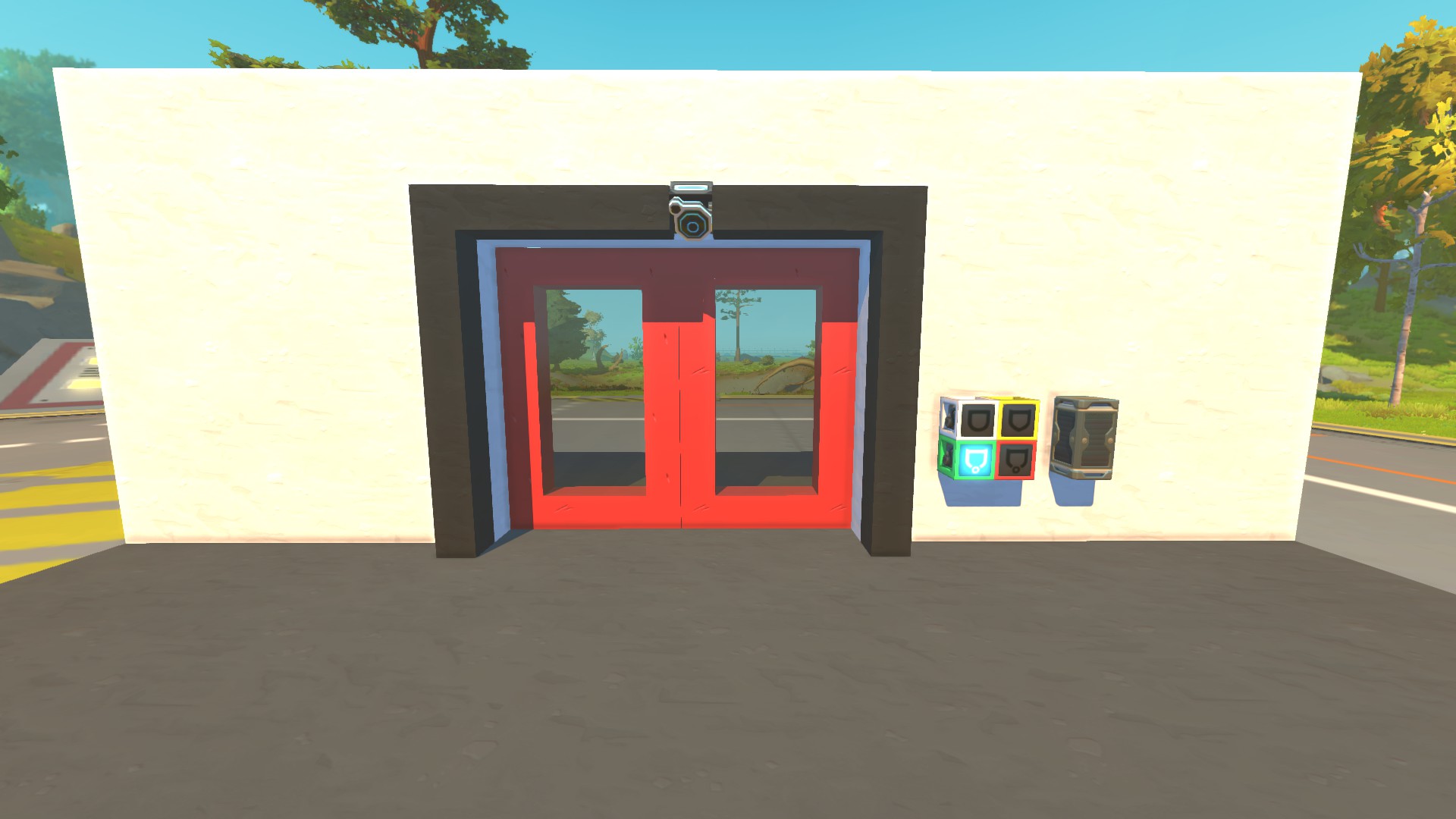
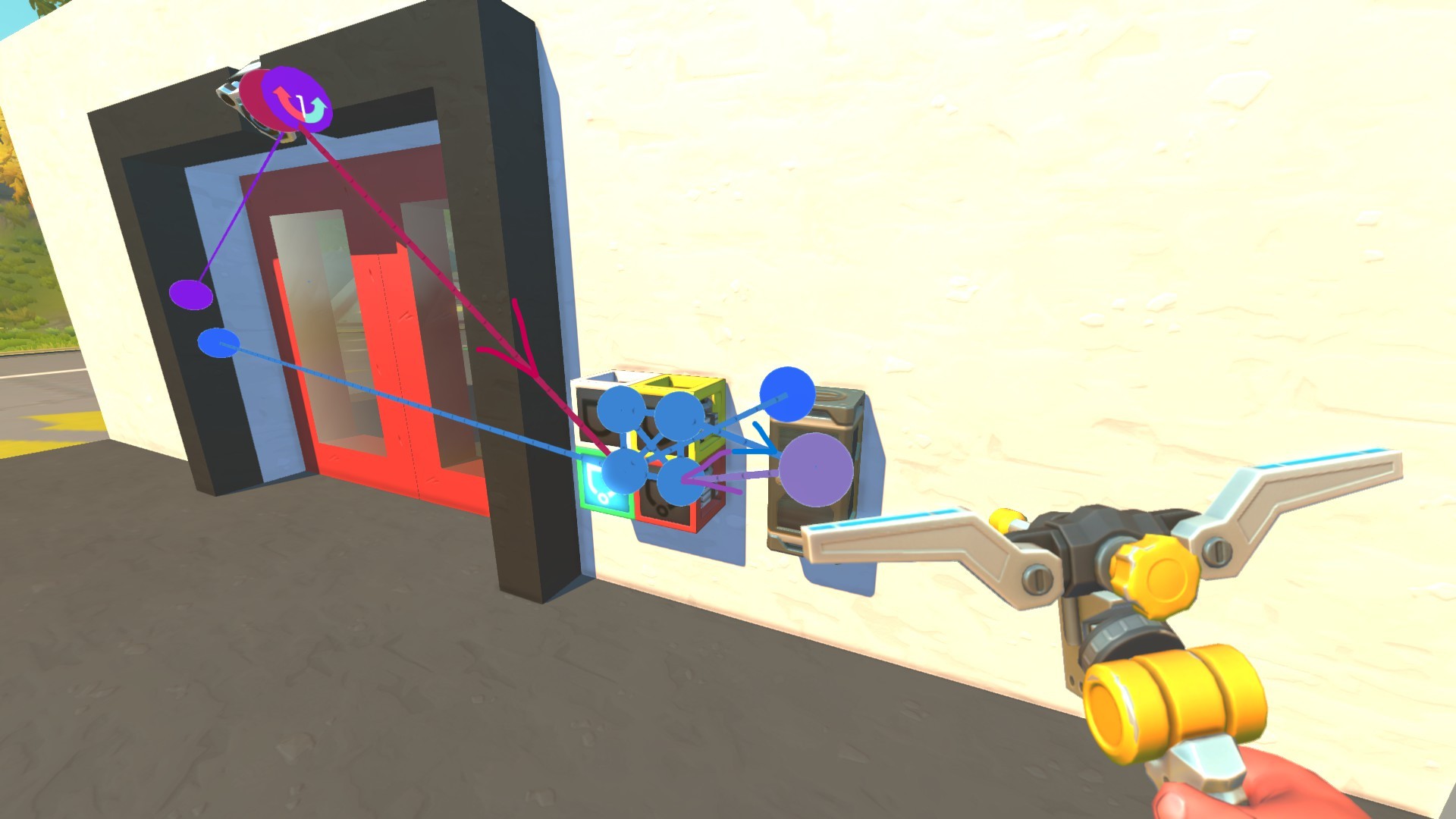
To replicate this behavior, you can once again utilize a memory bit. You wire a button as an input signal to activate the turn signal (setting the bit to ON). Then, you place a sensor in the underbody that detects the wheel. Once the wheel finishes turning, the sensor sends a signal to deactivate the turn signal. This feature requires additional logic to send a signal only after the sensor is deactivated, so it's not fully shown. The purpose of this guide is to give you an example of how you can make use of these memory bits, not to replicate existing builds. Still, this is a relatively simple setup that will make your creations way more flashy, so I encourage you to experiment!
Combining Multiple Memory Bits
Although singular memory bits can have its own uses, I've also already said that they behave as glorified switches. The real magic of memory bits comes when you combine multiple of them into a large circuit to perform complex actions.
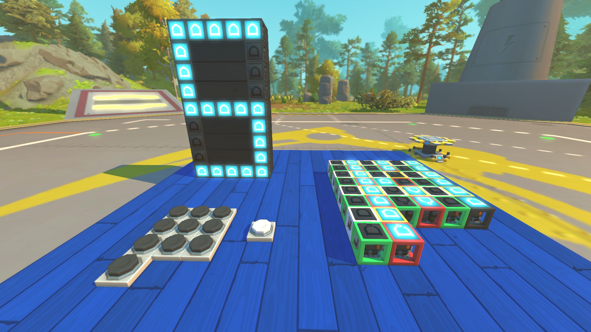
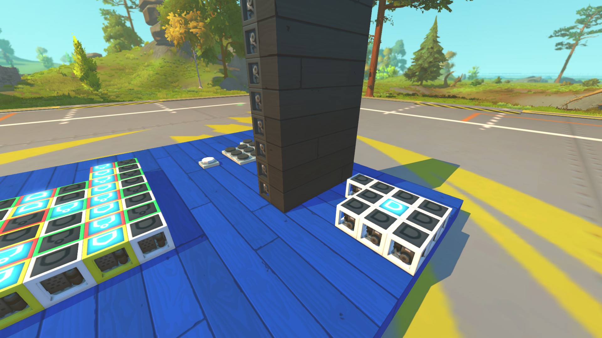
This particular setup uses 10 memory bits (for numbers 0-9) to display every possible digit. Below is an image of the wiring used to make it possible:
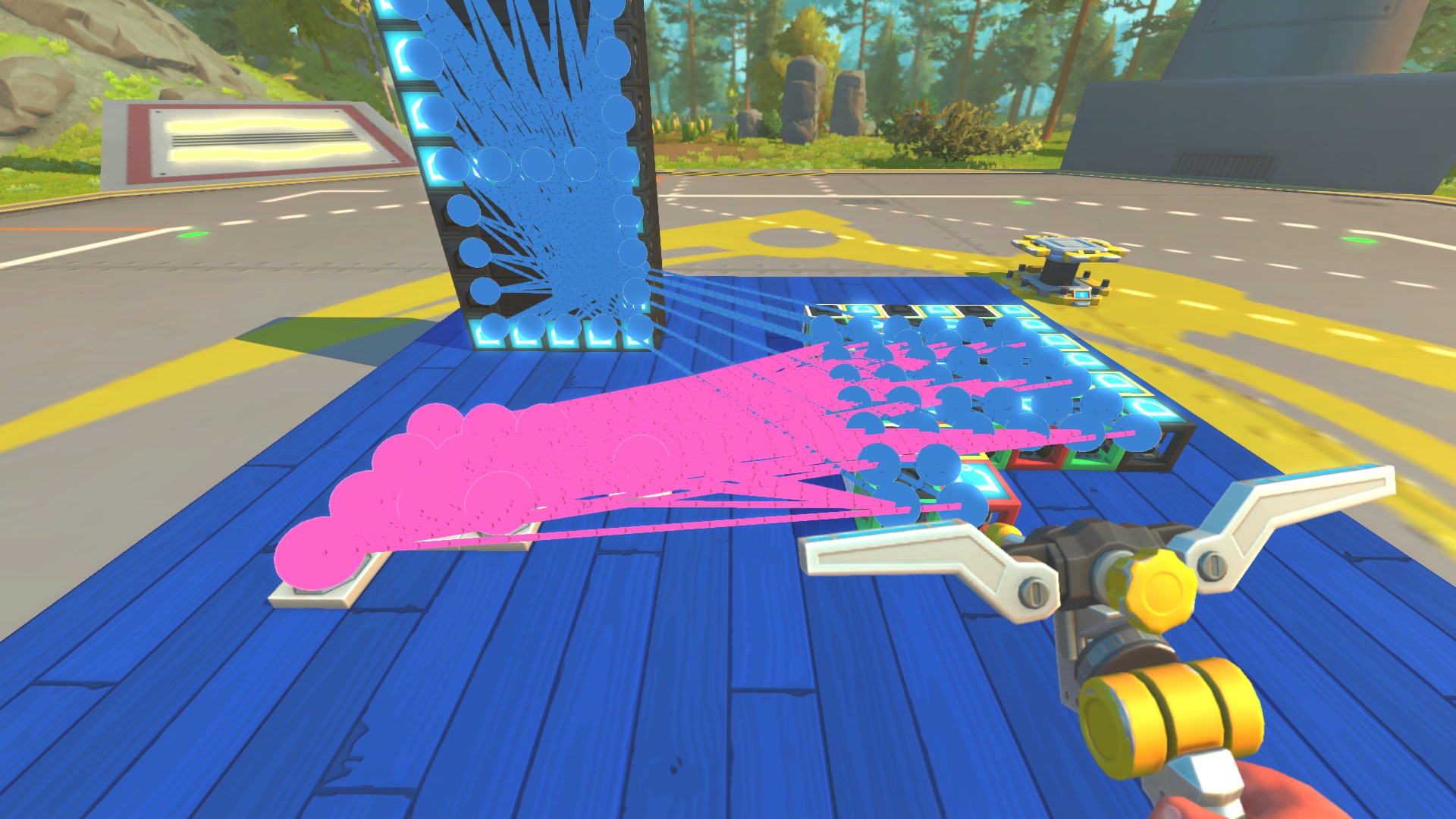
At a first glance, it can look pretty overwhelming and difficult to make, but it's really not, so let's break down how it functions so you can understand it. If you've already tried playing around with singular memory bits, this should be pretty easy for you to pick up on.
In this case, each shown memory bit's function is to store a different digit - that's why you need exactly 10. If, for example, the first memory bit is active, it will show the number one (using OR gates for the display). When you press the button associated with digit number 1, it acts as an input to turn on the first memory bit while also turning off every other memory bit. This ensures that only the memory bit associated with number 1 will be activated.
Other buttons are wired in a similar way - for example, the second button will turn on the memory bit associated with number 2 and turn off every single memory bit that isn't number 2. You can also see that there is an 11th button - this one is used to turn the display off (turning every single memory bit off).
With this setup, you don't only have to make displays - you could also make timers, clocks, or different lighting systems connected to one global network of logic gates. The possibilities are truly endless here.
Using Binary Logic to Save Space
As you could see in the previous example of a 7-segment display, quite a large number of logic gates were used to make it all possible (77, to be exact). This means you need a lot of space to store the gates, and in Survival mode it would be really cost-ineffective.
To counter this, I would advise that for more complex creations that require storing a lot of data, you use binary logic. This part on its own isn't essential, and every desired circuit can be made without binary logic, but it can be incredibly useful for saving space and resources.
The exact number of all possible combinations can be described using a simple formula: 2^n, where n is the number of memory bits used. Let's say I'm using 2 memory bits -> 2^2 = 4. This means I'm able to store 4 different states using only 2 memory bits (which is just 8 gates in total).
For our example of a 7-segment display, I would need 4 memory bits to store all 10 digits (2^3 = 8 -> not enough, 2^4 = 16 -> enough). I've already saved 6 memory bits (24 logic gates) just by switching to binary!
One thing about binary you should keep in mind is that 0 is also a number - that's what every programmer will tell you, too. Why is this important? The formula 2^n already includes the combination of all zeros.
So, for example, let's say I've built a circuit consisting of 4 memory bits. The first combination will be 0000 (the default state). You will have to choose whether you want to use this exact combination for a specific action - for example, it could represent the digit 0, or it could represent the complete OFF state of the display.
There's nothing wrong with either method, just keep in mind that if you want 0000 to be your OFF state, that's one extra stored piece of data you have to account for. That would mean that the exact number of combinations needed for our 7-segment display isn't 10, but is, in fact, 11 (10 for all the digits and 1 for the OFF state).
If you choose the other route - meaning you use the first combination of all zeros to represent the digit 0 on the display - you only need to store 10 pieces of data. The complete OFF state of the display can then be achieved by using a simple master switch.
This particular setup has one major added benefit: once you turn the display off, the digit that was displayed last will be remembered by the memory circuit. This means that once you turn the master switch back on, it will immediately display the last shown digit.
If you choose to store the OFF state as a combination inside your memory circuit, you don't get this bonus - turning it off actively changes the value stored in the circuit, wiping your previously stored data, so you need to choose the best approach for your desired build accordingly.
Making a Simple Binary Circuit
Now that we've moved past the boring theoretical stuff, let's have a look at what it all means in practice. Don't worry, it's not as difficult as you might think, and once you understand it intuitively, you'll have no problem developing your own circuits.
For this example, I've chosen three individual lights (red, green, and yellow) that I want to wire in such a way that I'll have three scenarios:- Only the red light is active
- Both the red and green lights are active
- All three lights are active
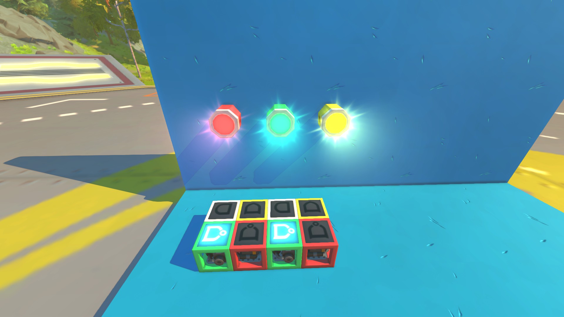
I've also made the decision that I want the complete OFF state to be stored inside the memory circuit. Therefore, to achieve this, I need to store 4 pieces of data. You can think of this example as lights for your car - you have your low beams, then your high beams, and lastly your fog lights, which you want to activate in this specific order.
To store 4 pieces of data, I only need 2 memory bits in total. All possible combinations alongside their desired actions are shown in the table below:
Firstly, you want to wire your buttons correctly. For this example, I'll be using 4 buttons to achieve every single action, which is the simplest solution. The first button is used to turn every single light off - therefore, you need to achieve the state 00. To do this, you wire the button to turn both memory bits off, as simple as that.
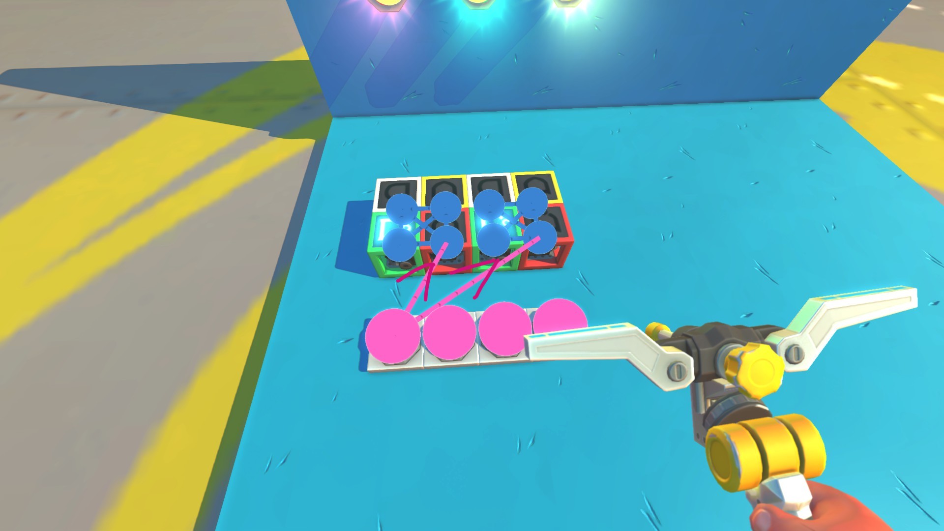
The second button is used to turn the red light on, which is the 01 state. To do it properly, you wire the button to turn on the second memory bit, while also turning off the first bit. This is very important: you always want to wire all buttons to every single memory bit, either turning them ON or OFF. This ensures that the desired combination is always the same, no matter what combination was active before.
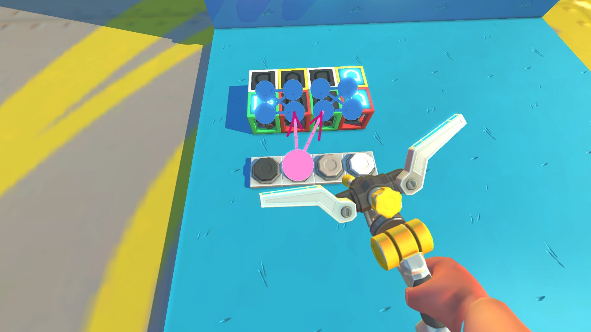
The remaining buttons are wired in the same way, always connected to both memory bits, either turning them on or off based on which combination you need to achieve, as shown below.
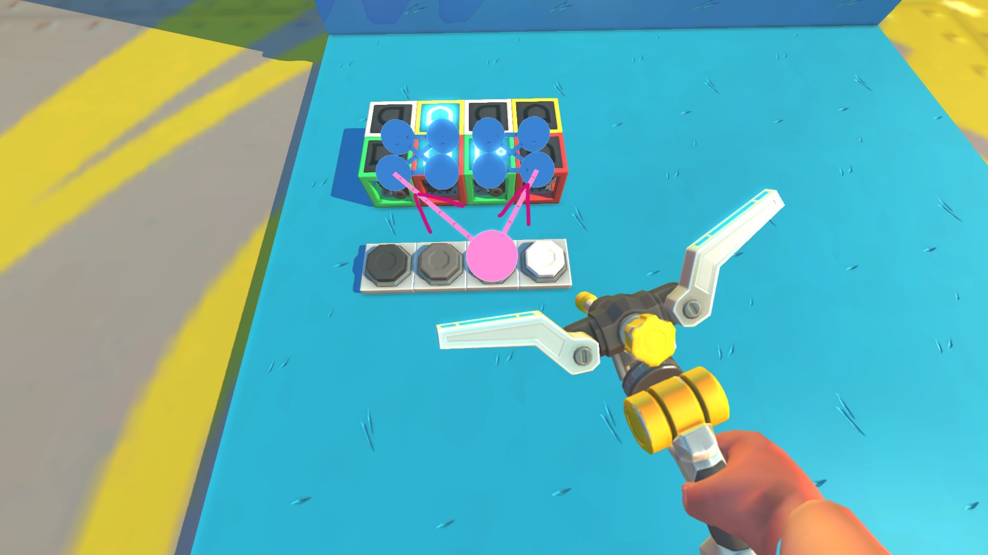
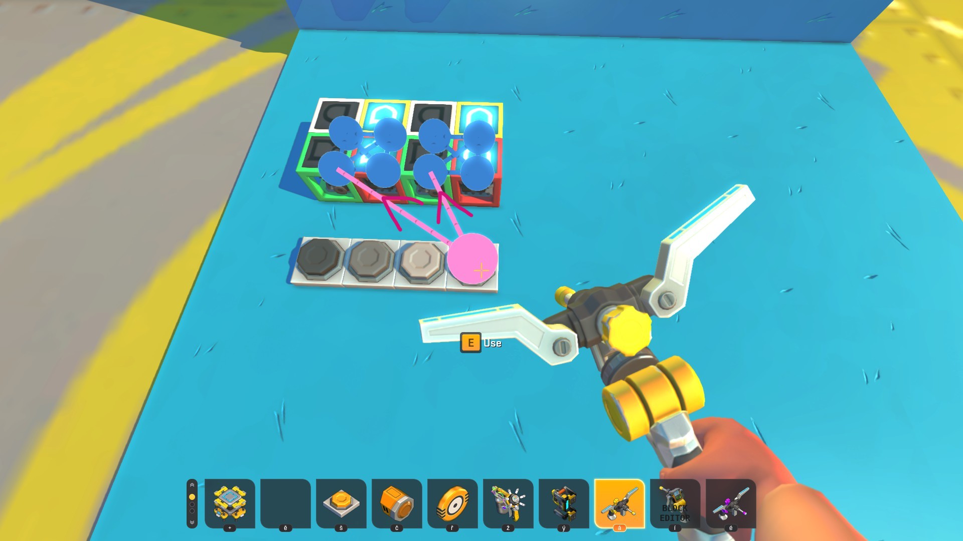
What we have now is a memory circuit that can store every possible combination of ones and zeros. In this state, you can't use it to control the lights just yet - first, you need a decoder that will read these combinations.
A decoder is a very simple addition: it only uses AND gates to read the specific states. Since we have 4 different combinations, we'll need 4 additional AND gates (technically you only need 3, because the first one reads out the complete OFF state, but it will still be shown just to make things clearer).
To decode the OFF state (00), I'm just taking the input from both green gates of the memory bits, which are active when both bits are off.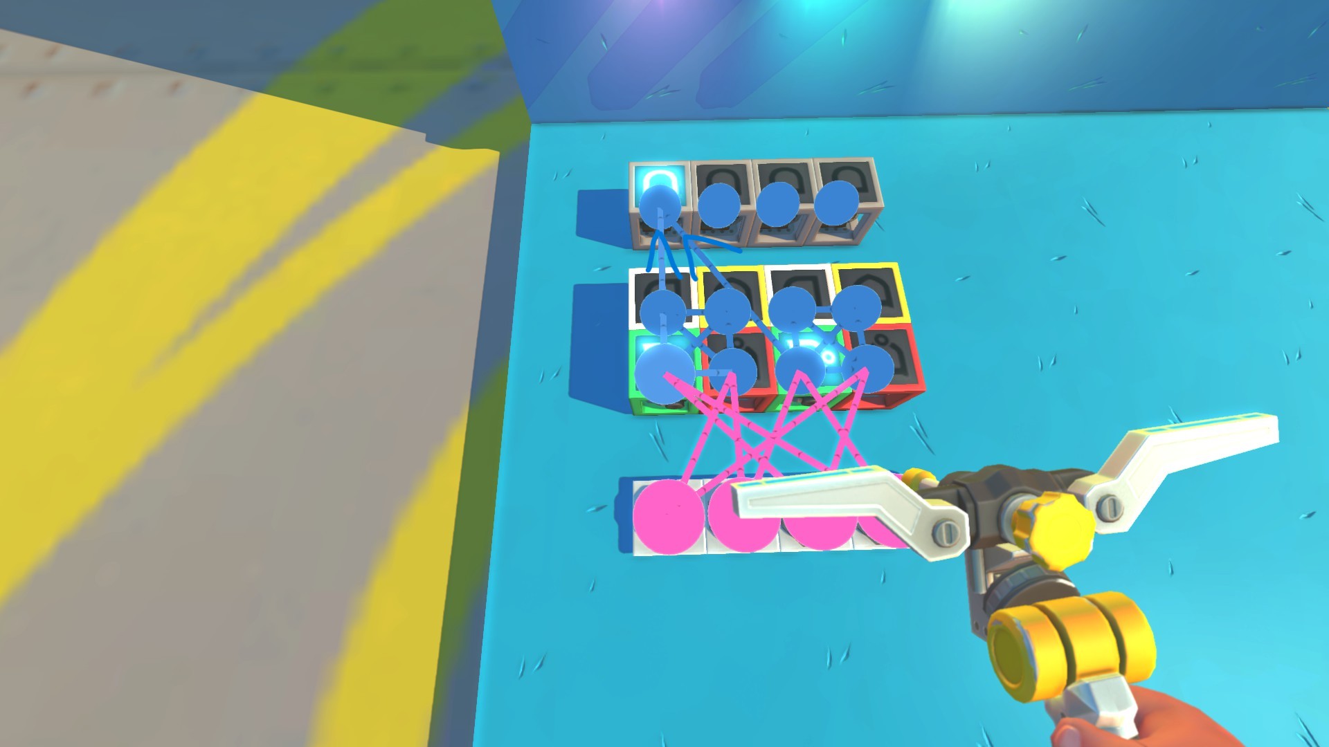
To decode the second state (01), I'm taking the input from the green gate of the first memory bit (when it's off) and the input from the yellow gate of the second memory bit (when it's on). Both of these signals go into the second AND gate.
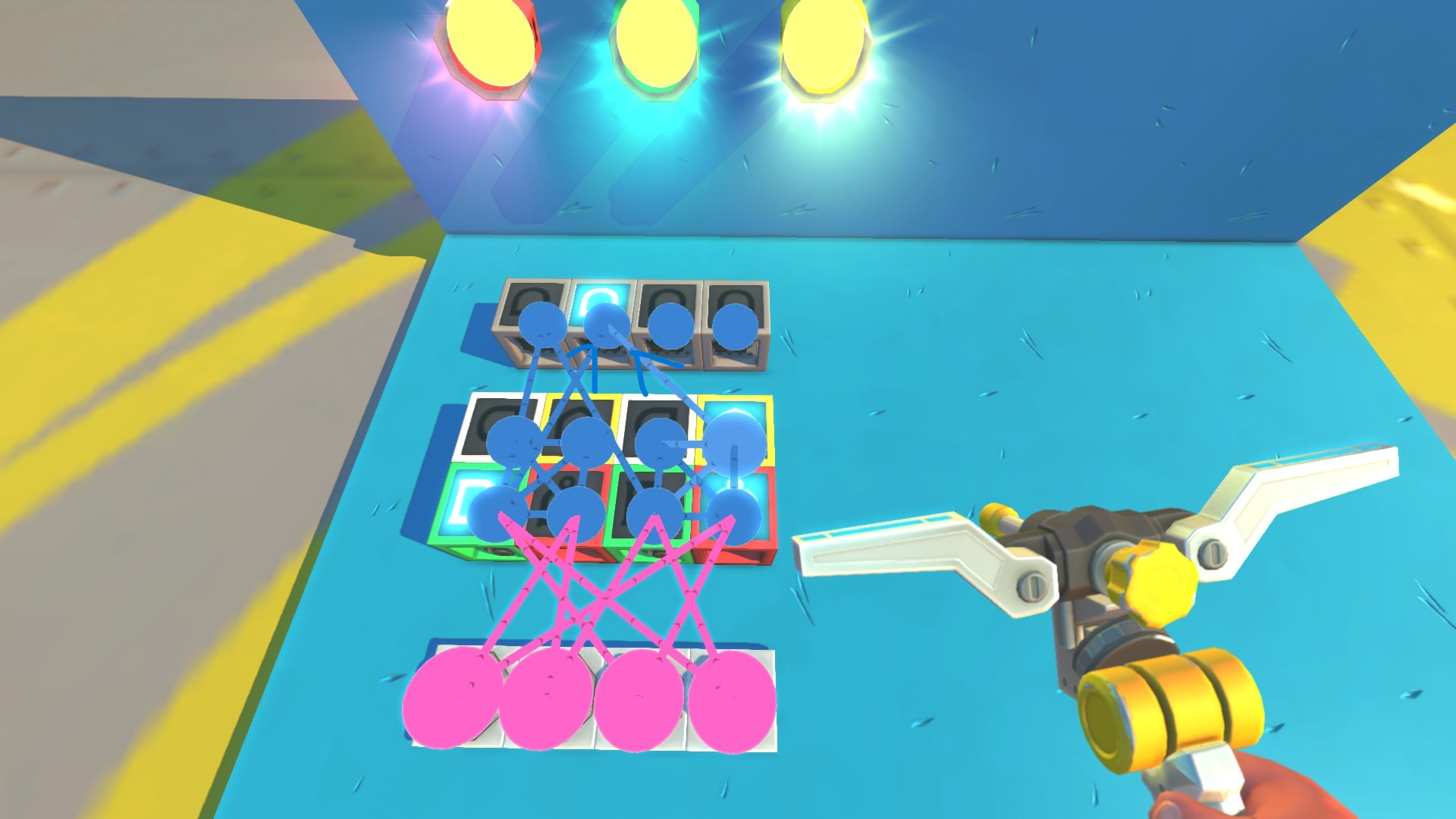
To make things easier for yourself so that you don't always have to remember the exact combinations, I find it much more straightforward to activate the desired combination first. Then, you can simply connect the gates that are currently active to the decoding AND gate. After connecting every gate, the wiring looks like this:
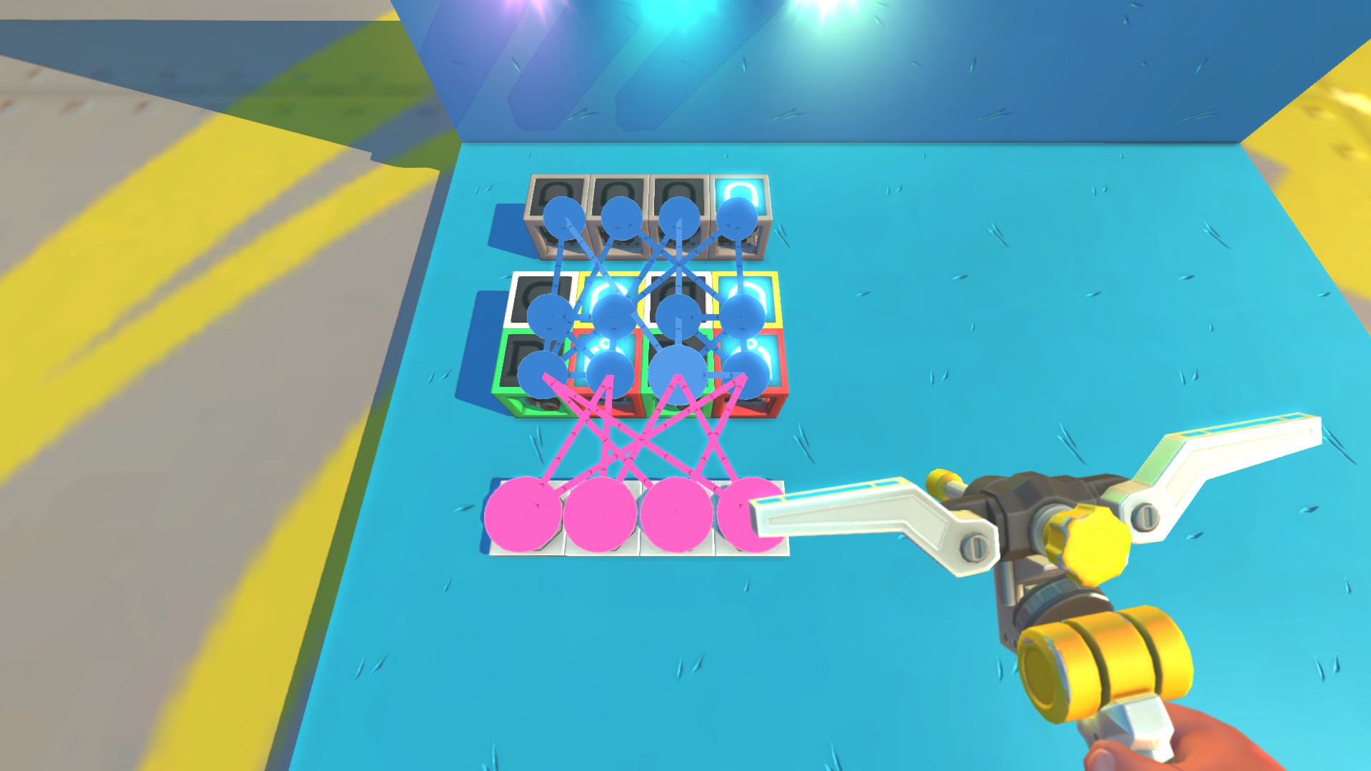
Before we wire all the lights, there's one final addition that we need to do, and that's adding OR gates based on when the lights need to be active. The red light needs to be active during the combinations of 01, 10, and 11. To achieve that, I'm just taking the input from the three corresponding decoding AND gates and wiring them all into one OR gate.
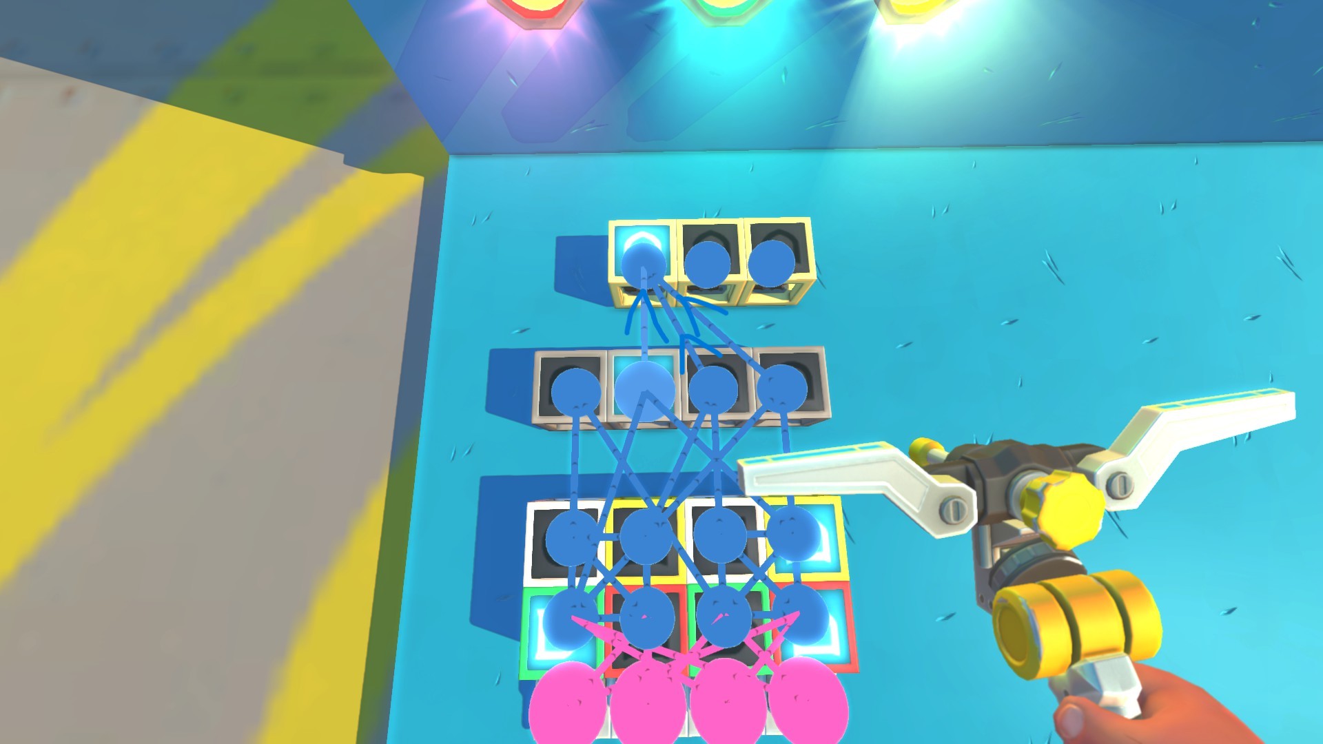
Then, the green light needs to be active during the combinations of 10 and 11, so I'm only taking the input from the last 2 decoding AND gates and wiring them into a different OR gate.
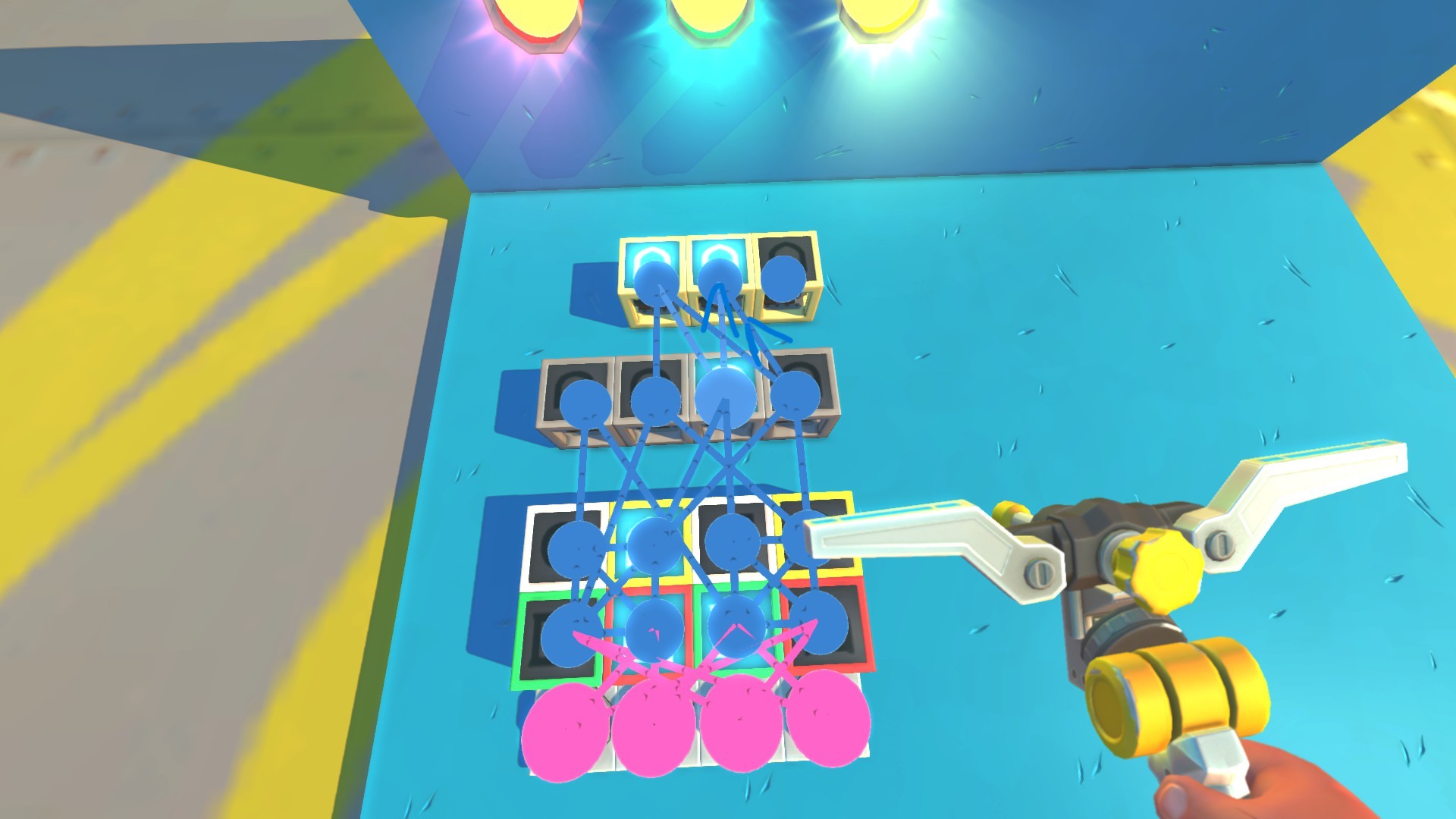
The yellow light is only active during the 11 state, so you can either wire this signal into a third OR gate or wire it directly into the light itself. With all that, you've successfully created a binary memory system able to control all three lights in the desired order!
Using One Button to Achieve Every Combination
The example shown in the previous chapter was already a pretty decent way to do binary logic. Still, having so many buttons can get messy and counterproductive, especially when we take into account that a single seat can handle only 10 different inputs.
My solution to this problem is to use a single button to cycle through all combinations. This is a fairly simple implementation and is once again based on the very same decoder logic that we used before.
For this example, we will utilize the same build used to control the lights. First, I remove all the buttons that were previously controlling the combinations. Then, I implement a new row of 4 AND gates that will be used to cycle through all combinations.
Then, I add a button that is connected to all of these AND gates. Since these are AND gates, they will only activate when all of their inputs are active. We can utilize this behavior to make a specific gate turn on only when a certain combination is active.
Therefore, I've connected all of the gates from the decoder (gray gates) back into these AND gates (white).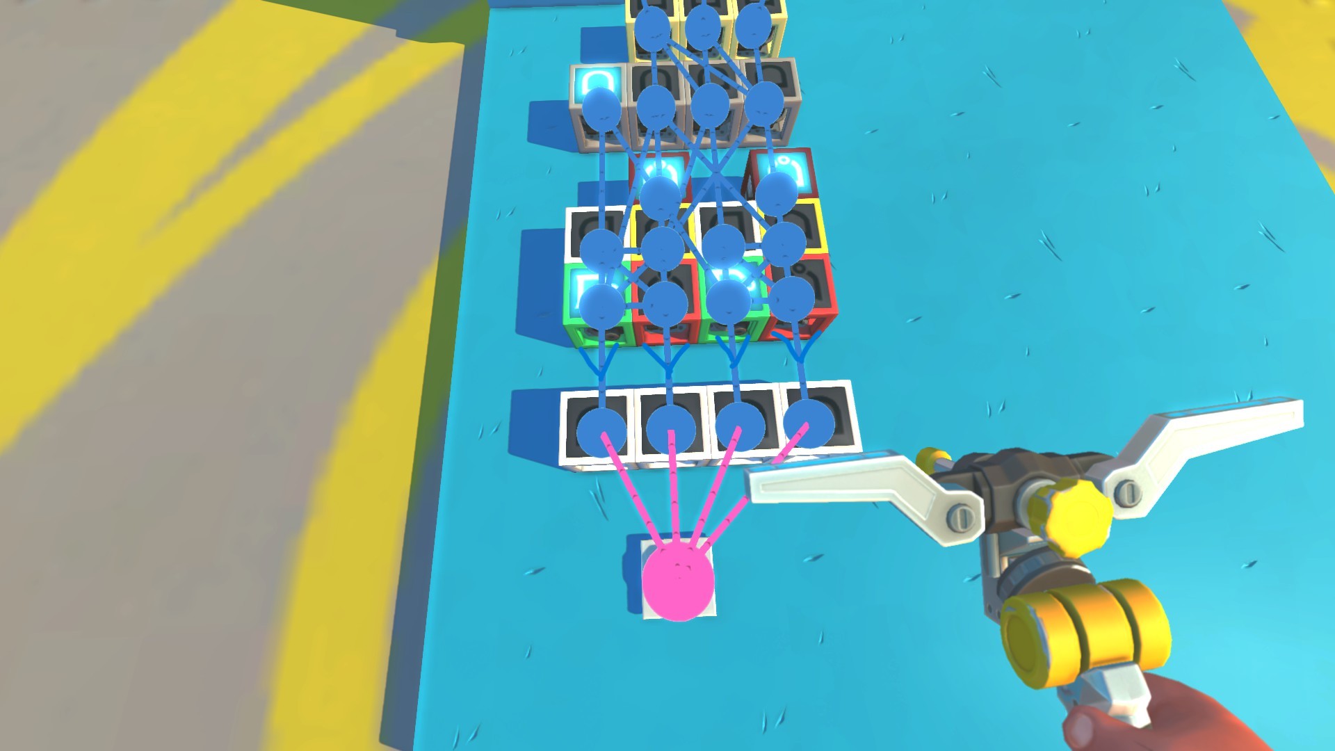
The way you then connect the white AND gates to the memory bits is basically the same as before when we used buttons. The only difference is that the inputs have now shifted - the first white gate activates the 01 combination, the second one triggers the 10 combination, the third one the 11 combination, and the last one is used to reset the cycle, turning the circuit back to the 00 state.
If you've successfully built this, there's still one more issue you might have run into - the gates go into an infinite cycle when you hold the button down, and it can be glitchy even if you don't hold it for too long.
To fix this, you need to build a sort of buffer for the input button that will limit the length of the sent signal. The circuit is very simple, as it only uses one NAND gate (red), one AND gate (green), and a timer. You connect your button to both of these logic gates, connect the NAND gate to the timer, and then the timer back into the AND gate, which is then used as the new input for all of the white gates.
The timer needs to be set to only 2 ticks (50 ms), which is enough to break the infinite cycle while also enabling you to press the button normally without causing the memory bits to glitch. With this setup, even if you hold the button down, you'll always only move forward from one state to another.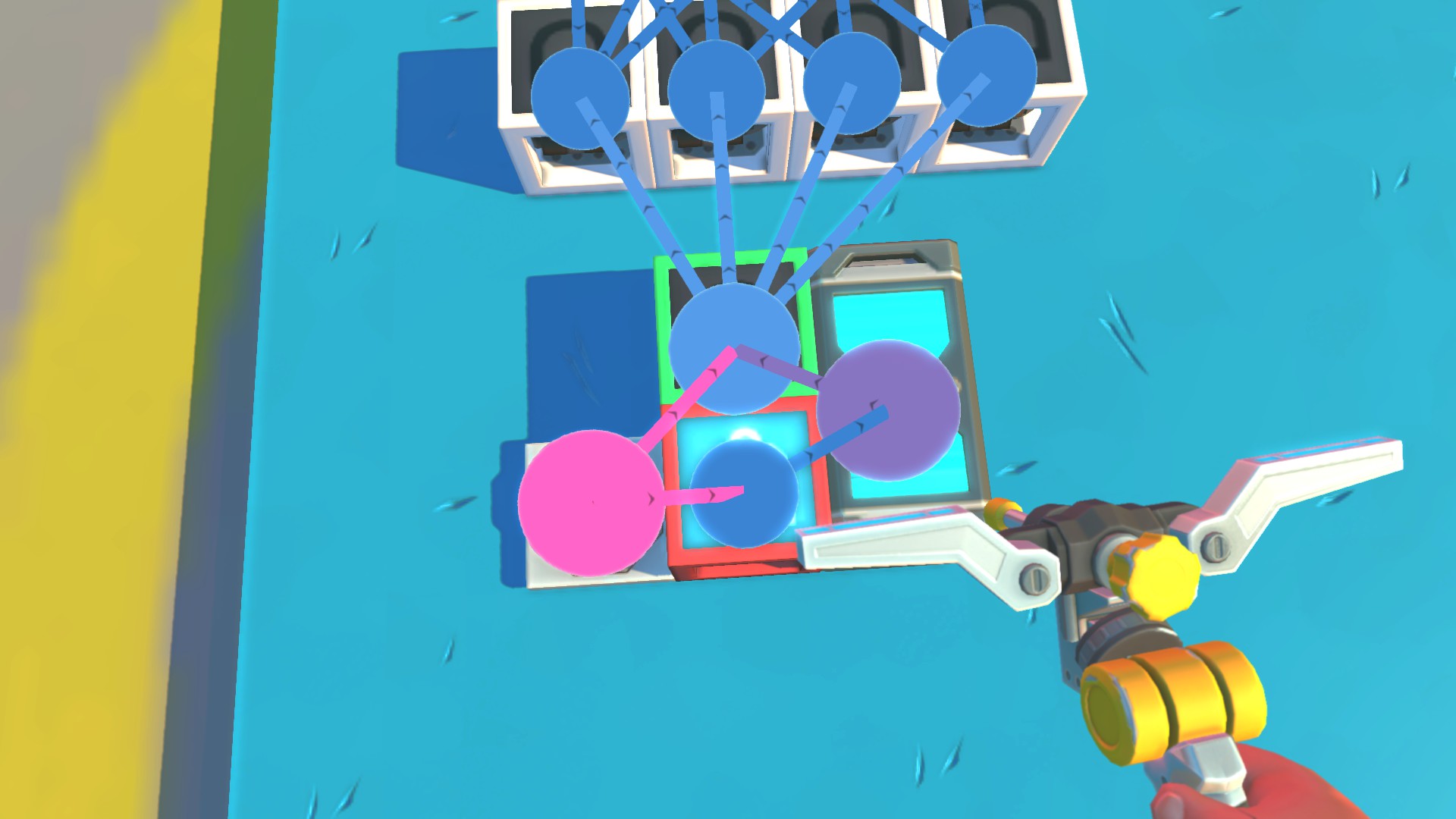
Now, you've successfully built a binary memory circuit using only one button to cycle through all the possible combinations! If you wanted to, you could also add a second button that would go in the opposite direction (cycling back) or a master turn-off switch - that's all up to you.
Improving the 7-segment Display
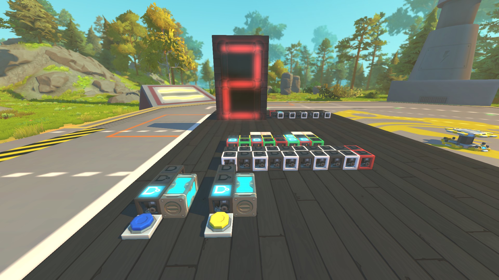
The full tutorial on how to build this isn't shown, since you already have all the necessary knowledge to build it on your own. Therefore, I encourage you to try to recreate it or come up with your own use of binary logic!
As you can see, it uses way fewer memory bits than before, and I've also implemented two buttons to cycle back and forth, as I mentioned earlier. This creation uses the combination of 0000 to display the digit zero, there is no OFF state.
Therefore, to turn it off, an additional master switch would be needed to power off the gates that activate the lights. If you were to do that, the last displayed digit would always be remembered after turning the display off, which can be incredibly useful in some scenarios.
Making a Blueprint Edited Memory Bit
Now we're getting into the more advanced stuff. As I promised, we'll take a look at a blueprint-edited memory bit that eliminates the problem with 1-tick inputs. For this part of the guide, I'll be using Bingo's Block Editor.
The first thing you need to do is to wire an XOR gate back into itself. This is the heart of the whole memory bit, and since you can't do this in vanilla, you're going to need to do some blueprint editing. Also, don't worry - once you have your own blueprint-edited memory bit, you'll still be able to keep using it without any mods!
To start, you want to grab two gates. Then, make the first gate an XOR gate. The second gate's type doesn't really matter in this case, since we'll be deleting it later anyway. Now, wire the XOR gate to the second gate like this: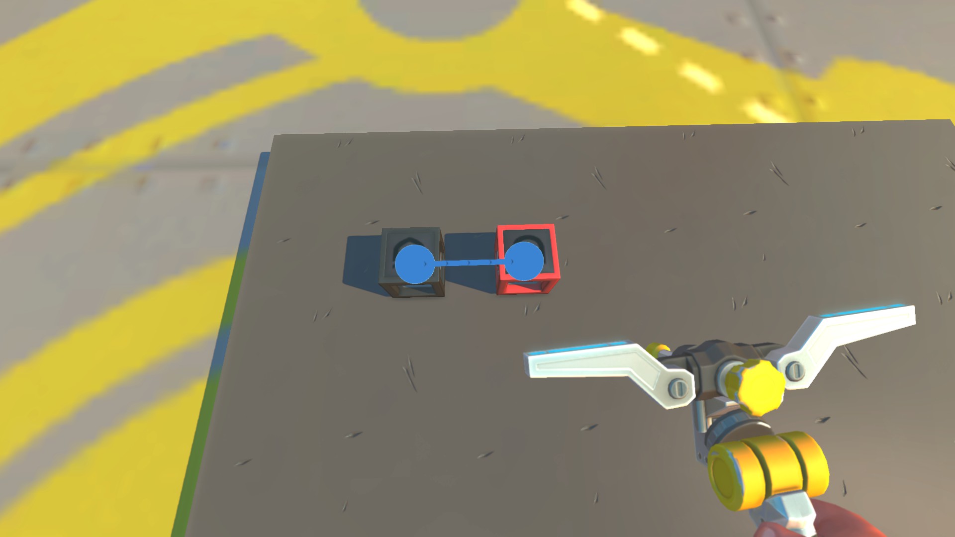
Moving on, now you need to grab your blueprint editor, select both gates (using right-click), and open the menu by left-clicking. You'll be greeted by this kind of menu:
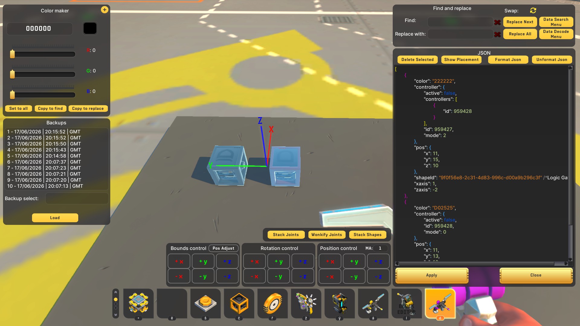
I've colored my XOR gate black. This can be found by the color code "222222" - that's how you know you're dealing with your XOR gate. The important sections you should focus on are "controllers" and "id". The controller section tells the XOR gate which other inputs it is connected to. In my case, the label is "959428", which is the second connected AND gate (red). Now, to wire the XOR gate back into itself, the only change you need to make is to ensure the number in "id" and "controllers" is exactly the same. Therefore, I've copied the id number 959427 and pasted it into the controllers section.
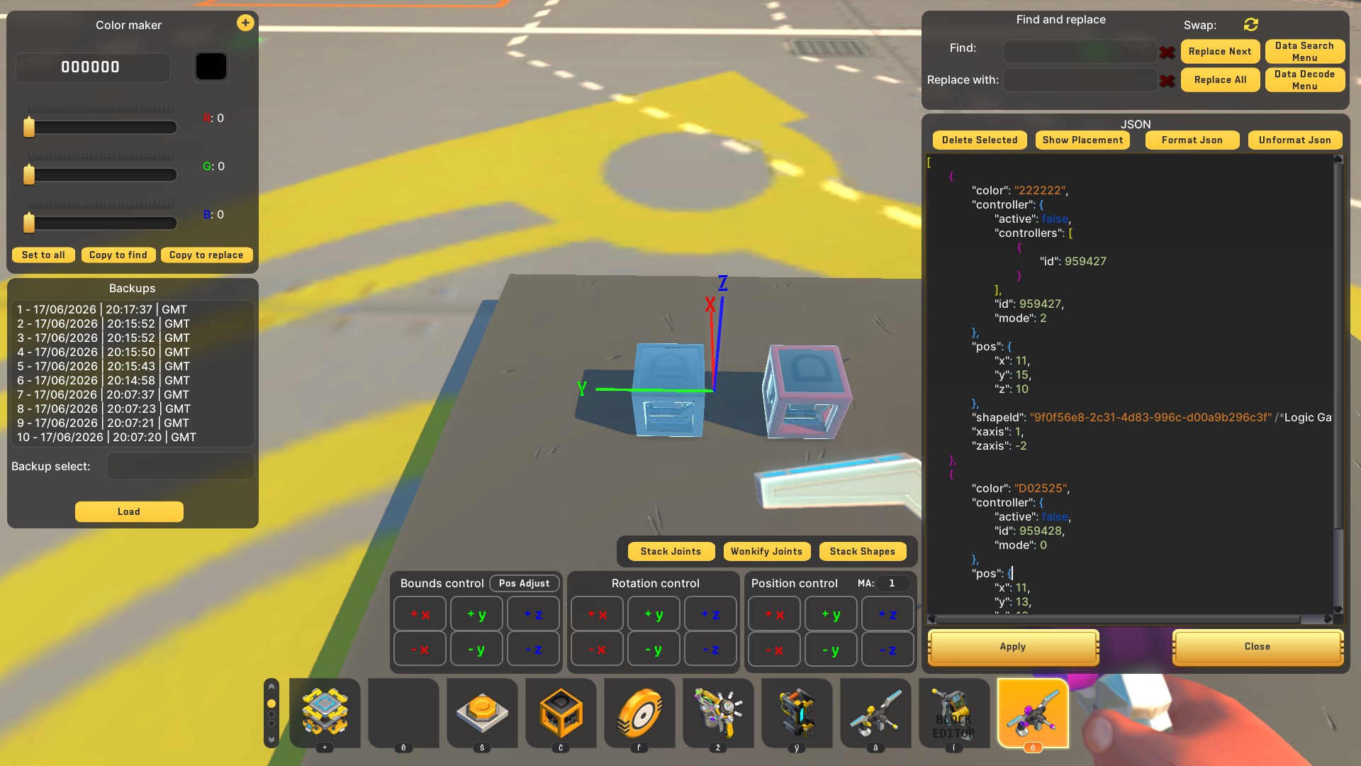
Once you hit apply, you're basically halfway done with the whole blueprint editing part. You now have an XOR gate that's wired into itself, and you can get rid of the second (red) gate!
This XOR gate is basically the most essential form of a memory bit, it doesn't require anything else. However, if you connect a button directly to it, you'll only see the gate flickering on and off when pressed. Unlike the standard, previously shown memory bit that requires inputs longer than 1 in-game tick, this sort of memory bit actually requires you to use strict 1-tick based signals to work properly.
To get around this problem, and to also have the standard ON/OFF inputs, we need two OR gates for our inputs and one NAND gate taking a signal from the edited XOR gate (yellow) to know when it's off.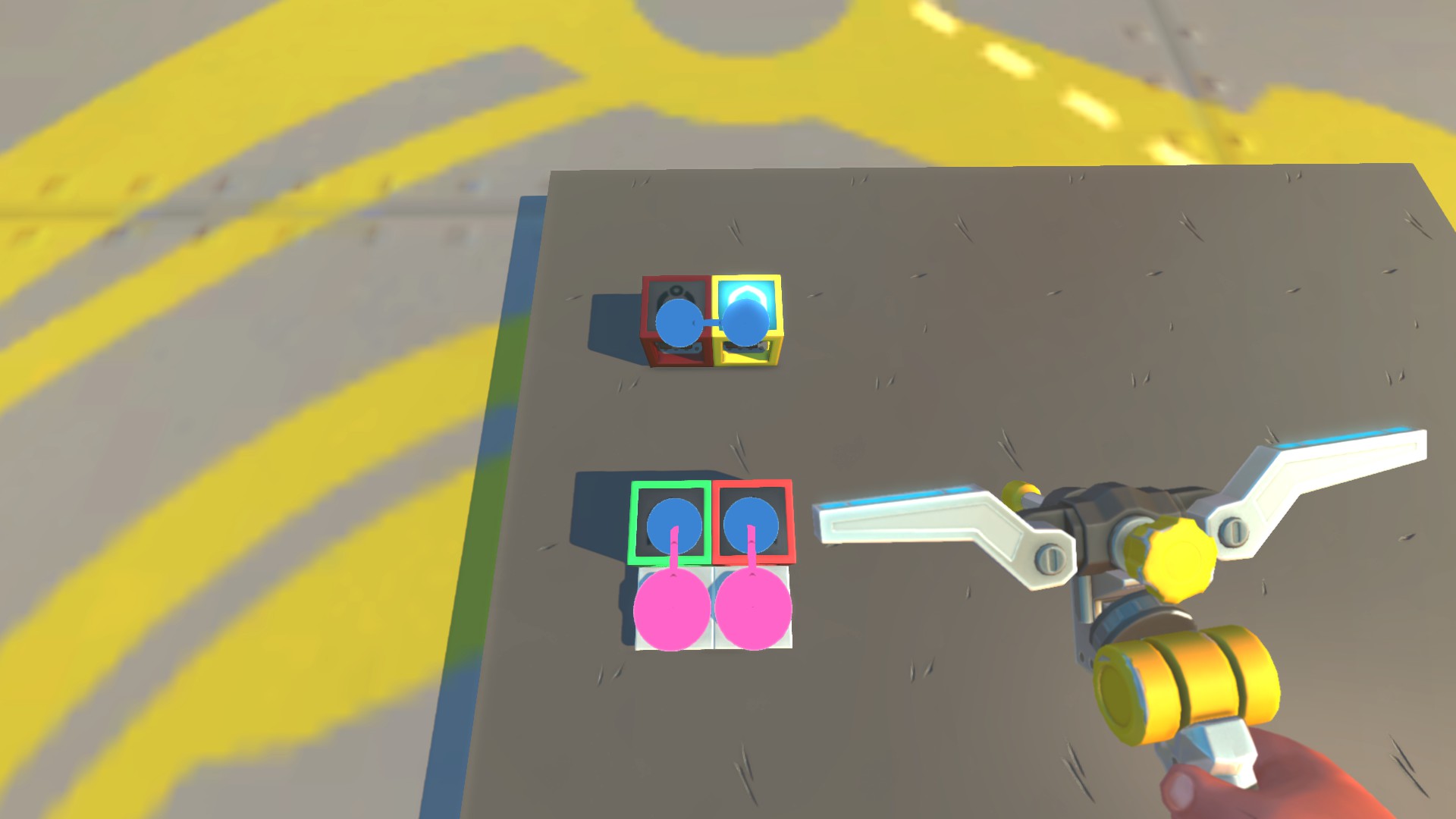
Now, take two more AND gates. Connect both input OR gates into them, and then connect the NAND gate (detecting the OFF state of the XOR gate) into one of them, and the XOR gate itself into the second AND gate.
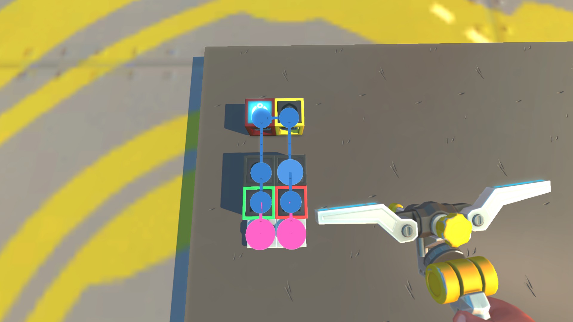
Next, we need another OR gate (white) that both black AND gates will go into. This OR gate will be used to send a signal into the XOR gate itself to change its state.
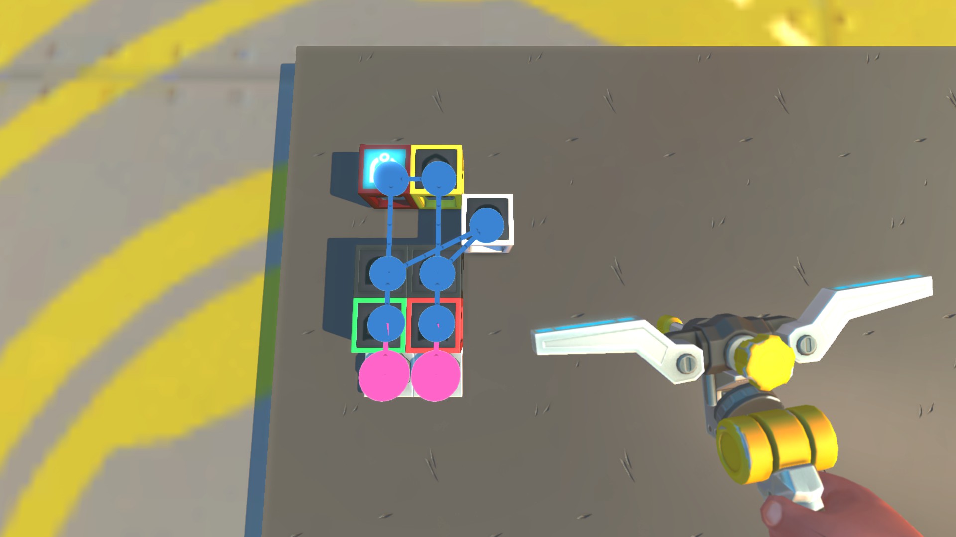
The final step is to introduce a buffer that will send a signal that is exactly 1 tick long. To do this, you only need one more NAND gate and one AND gate (colored gray). Wire the white OR gate to both the gray AND and NAND gates, then wire the gray NAND gate into the gray AND gate, and finally, wire the AND gate back into the XOR gate.
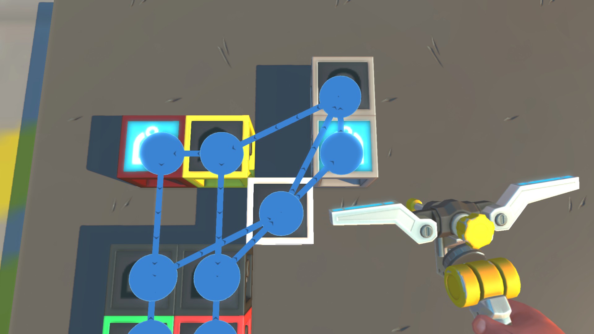
If you try to use the memory bit now, it will work flawlessly. However, there's one final detail that I like to do, and that's to move away all the unnecessary gates that we don't need to interact with. To do this, you can once again utilize Bingo's Block Editor, which is able to move gates without disrupting their connections. The only gates we actually need to interact with are the yellow, blueprint-edited XOR gate and both the red and green OR gates. You can move every other gate into a corner, and you'll end up with a flawless, compact memory bit:
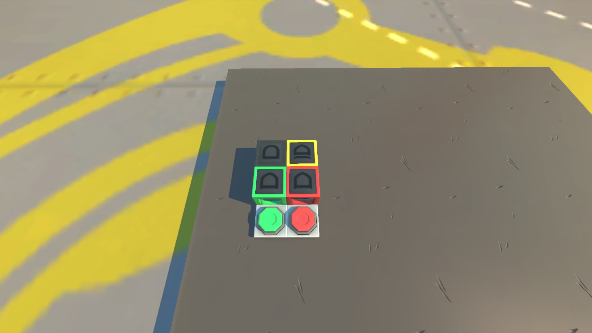
Also, if you don't want to go through all the hassle of blueprint editing your own memory bit, you can utilize my creation, which uses pretty much the same principle. You can find it here.
One final thing to take into consideration is that unlike the simpler-to-build memory bit, this type doesn't inherently tell you when the XOR gate is inactive. Therefore, you'll have to wire your own NAND gate from it every time you need to detect the OFF state, which is essential for binary logic. Other than that, it's a huge improvement over the standard vanilla design!
Delay in Logic Gates
We've already covered all the essential information about memory bits and binary logic. In this final part, I will briefly talk about how gates affect your creations when it comes to delay.
Every gate used in your creation introduces a 1-tick delay (25 ms). This doesn't seem like much at first, but if you're using lots of gates or are building a timing-sensitive creation (like a clock), you might run into issues.
In most cases, you don't really need to worry about gate delay, as it's not really noticeable. However, to optimize your builds and to make them respond quickly, I would suggest that you always try to use as few gates as possible.
When it comes to my blueprint-edited memory bit shown before, it's really good for most builds and will work every time. However, since it uses 9 gates, the delay could sometimes be noticeable. If you care about this sort of stuff, or you need your build to respond as quickly as possible, it's best to use the XOR gate as your memory bit on its own and wire only the most essential logic gates.
Other than that, as I said, for most cases, the delay isn't really noticeable for most builds, so you'll likely be fine. But if you're planning on making really timing-sensitive builds, just keep this information in mind.
Final Thoughts
Well, this is the end of my guide. I hope you've learned something new and that you'll now be able to make way more complex builds. Trust me, learning about memory bits and binary logic has completely changed the way I make creations - it allows you to do so much more than what is possible with basic switches.
But remember, I've only given you a guide to understand the basic principles. To truly master them, trial and error is the best approach, so don't be afraid to experiment. If you ever run into trouble, you can always come back to this guide or ask me anything in the comments.
If you've made it all the way through to this final chapter, thank you so much for reading, and I hope you'll be able to make some cool creations with your new knowledge!
- How raids actually work (Version 0.5.1)★ 5 (550)19k views867 ♥3 minUpdated 7 Apr, 2021
- Как пройти выживание?★ 5 (448)18k views700 ♥25 minRussianUpdated 12 Aug, 2020
- Все команды для скрап механик★ 5 (259)15k views475 ♥1 minRussianUpdated 1 Dec, 2023
- Robots and weapons concept proposal★ 5 (421)10k views182 ♥3 minUpdated 1 Apr, 2022
- How Does Fuel Consumption Work? Which Engine Is the Most Efficient?★ 5 (182)10k views152 ♥3 minUpdated 16 Oct, 2020
- Русификатор для Scrap Mechanic by Pro100DarkTV (v2.5)★ 5 (317)9.9k views516 ♥1 minRussianUpdated 19 Jun, 2021






- Upgrading to PremiumTeam Fortress 2★ 5 (20k)1441k views11k ♥6 minUpdated May 11, 2022
- No More Room in Hell Official ManualNo More Room in Hell★ 5 (2.8k)569k views2.1k ♥29 minUpdated Apr 22, 2019
- NMRiH Community Hosting GuidesNo More Room in Hell★ 5 (526)351k views653 ♥1 minUpdated Aug 10, 2022
- ULTIMATE GUIDE FOR GAME DEV TYCOONGame Dev Tycoon★ 5 (5.8k)326k views10k ♥4 minUpdated 23 Jan, 2014
- How to 'Git Gud' Soon™MORDHAU★ 5 (2k)318k views3k ♥68 minUpdated Nov 16, 2024
- Лучшие кооперативные игры SteamPAYDAY 2★ 5 (1.5k)315k views2.1k ♥56 minRussianUpdated Apr 27, 2025






This guide was created by its original author on the Steam Community. Are you the author and want it removed? Request removal.