A LIQUID OXYGEN/HYDROGEN MACHINE FOR THE NORMAL MODE
INTRODUCTION
This design is intended to help players achieve the Escape Imperative with a design that’s been proven to work in the Normal Mode. This is NOT intended to be an “ultimate” machine that achieves some sort of perfection in perpetuity: you may want to explore other designs if that’s what you are looking for.
WHY AN ALTERNATIVE DESIGN
The flaws you can notice in such designs are namely:
- SPECIAL MATERIALS: the extensive/liberal use of special materials, such as super-coolant, Thermium and Insulation, reveal that all of these designs have likely been conceived and built in Sandbox Mode. In Normal Mode it takes an incredible amount of work to make a small batch of these special materials, so these designs are simply not viable outside Sandbox Mode.
- STEAM TURBINE: in theory, the “heat generated by the aqua-tuner is then used by the steam turbine to generate electricity”, and that sounds awesome, right? Well… in reality, setting up a steam turbine that performs as intended is a lot more complicated: it’s a full project on its own with a set of issues. And these designs will fail if the turbine doesn’t work continuously, or doesn’t absorb as much heat as theorized/purported.
THE ROAD AHEAD
Before you can even build a rocket with a Hydrogen Engine, you will have to start a Space Program, send rockets to various planets and collect data and then do the research for the Hydrogen Engine.
Thought challenging, the early-mid stages of the Space Program are a fun part of the game, and there are some good guides out there on how to build and fuel both Steam Engine and Petroleum Engine rockets, and how to maximize the amount of data they collect so you can advance your scientific research towards the Hydrogen Engine. Hence, I will leave that part to you.
While you collect data for research, build your Star Port and gain experience with rockets, you can start preparing and accumulating the resources you will need for your Hydrogen rocket.
Here’s the list of manufactured materials and rough quantities that you will need for this design:- STEEL: 12,000 kg (12T)
- CERAMIC: 14,000 kg (14T)
- SUPER-COOLANT: 1,000 kg (1T)
- THERMIUM: 12,000 kg (12T)
- PETROLEUM: 10,000 kg (10T)
And here’s the list of resources you will need to accumulate your first trip to the Temporal Tear:
- POLLUTED WATER: 30,000 kg (30T) @45C or less.
- HYDROGEN GAS: 2,600 kg (2.6T)
- OXYGEN GAS: 2,600 kg (2.6T)
Note that the exact amounts of Hydrogen and Oxygen needed will depend on the number of modules installed in your rocket. The ONI-assistant Rocket Calculator (on the Internet) is an excellent tool to determine the exact amounts of oxidizer and fuel needed for the mission. This design uses a relatively small amount of super-coolant, which absolutely necessary because in its liquid for it can reach the low temperatures needed to make liquid hydrogen. We then need some Fullerene, and looking at the Star Map, it may seem that Fullerene is out of reach of petroleum rockets.
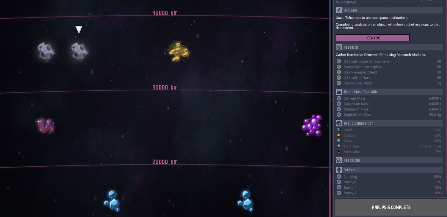 In the case of this map, there’s an asteroid 30,000 km away with “trace amounts” of Fullerene. But don’t despair, that means that if we send a cargo rocket there, it will return loaded mostly with stuff we don’t need, but also a small amount of precious Fullerene.
A Petroleum rocket with two cargo bays sent to this asteroid, will return with about 3kg of Fullerene. Now, since there’s a ratio of 100:1 of super-coolant to Fullerene, and because this design only uses about 1T of super-coolant, we only need about 10kg of Fullerene, so 3 or 4 trips to this asteroid will provide us all the Fullerene we need.
To make Thermium, we do need some Niobium, though a single cargo trip with a Petroleum Rocket to a planet with Niobium will suffice, as we can fabricate more Niobium at home after we make our first batch of Thermium and convert that back to Niobium at a 1:1 ratio.
BUILDING THE MACHINE
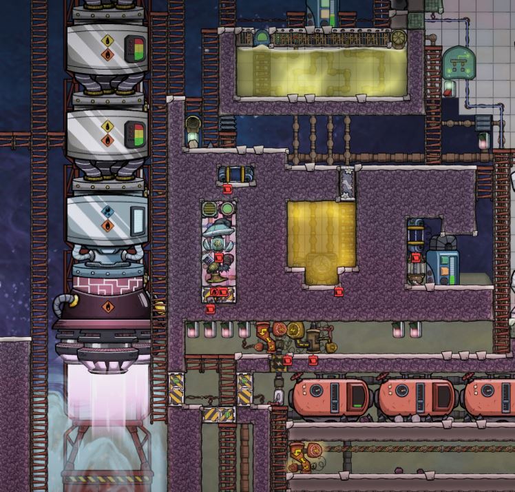
Our first step to build the machine is to actually build the rocket with its engine and oxidizer/fuel tanks. We try to build the rocket in the outer space vacuum as much as we can, and then we will build the machine around the rocket.
We start with the basic structure shown below. The insulated walls are made out of Igneous Rock (very abundant in the map), and we install dry-wall where we will have liquids (so they don’t drain to the space vacuum).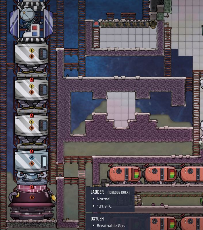 The next image shows the machine with all its inner components built, and most of the electrical, plumbing, gas ducting and automation wiring done.
The small room to the left is fully lined with Thermium Temp-Shift plates (this is the most expensive room in this design). If you guessed it, this little room will be the cooling chamber where the liquid oxygen/hydrogen will be produced.
All the machines and automation elements are made out of steel.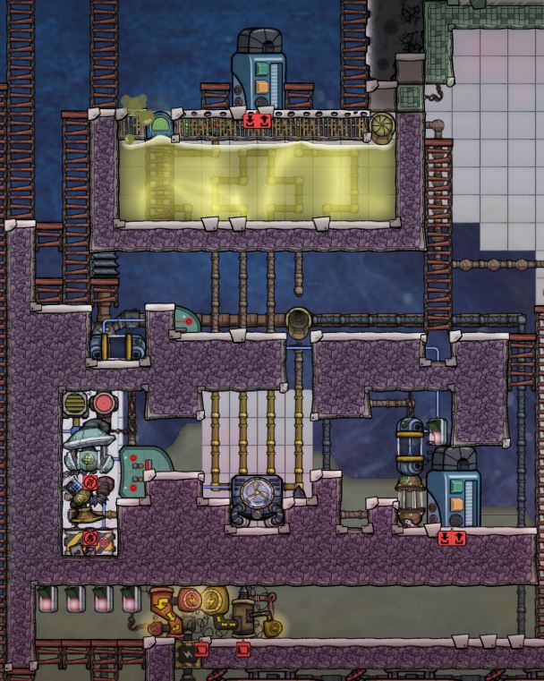 Before you finish all the walls (and close the machine), it is important that you make sure that all the inside wiring, plumbing and ducting is completed, otherwise you will have to get back in if you forget to build something.
Here’s the Electrical:
Before you finish all the walls (and close the machine), it is important that you make sure that all the inside wiring, plumbing and ducting is completed, otherwise you will have to get back in if you forget to build something.
Here’s the Electrical: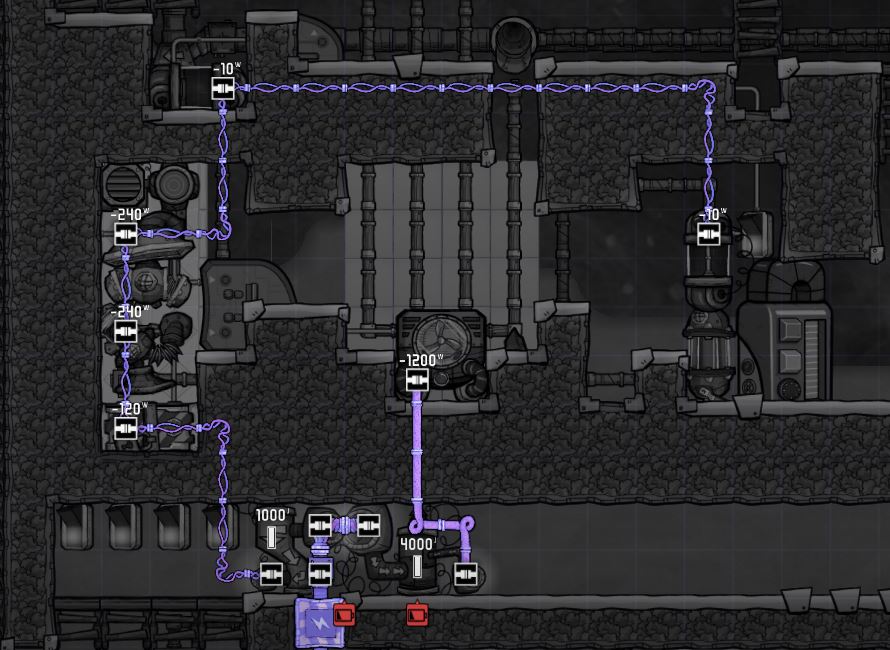 The plumbing is next (almost finished): the radiant pipes inside the cooling chamber are all made of Thermium. The radiant pipes inside the aqua-tunner chamber are made of steel, with the exception of the four pipe sections closer to the aqua-tunner, which are also made of Thermium.
The Insulated Pipes are made of Igneous Rock, except the pipes for the liquid pump’s output, which are made out of Ceramic (and will carry out the liquid oxygen/hydrogen from the cooling chamber to the rocket).
The plumbing is next (almost finished): the radiant pipes inside the cooling chamber are all made of Thermium. The radiant pipes inside the aqua-tunner chamber are made of steel, with the exception of the four pipe sections closer to the aqua-tunner, which are also made of Thermium.
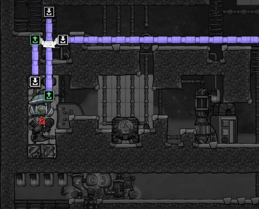
The Insulated Pipes are made of Igneous Rock, except the pipes for the liquid pump’s output, which are made out of Ceramic (and will carry out the liquid oxygen/hydrogen from the cooling chamber to the rocket).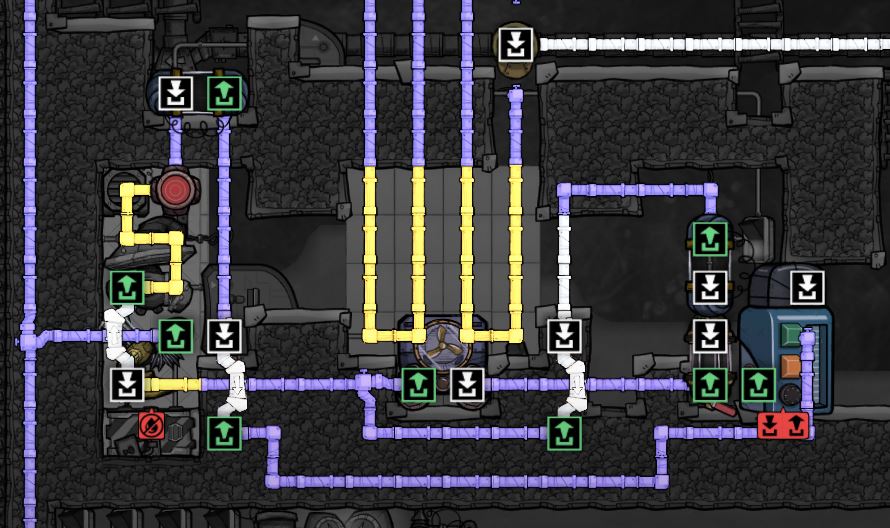 The gas duct design follows and it is very simple:
 The automation wiring diagram is shown next. I will also explain what the automation elements are and what are they supposed to be used for:
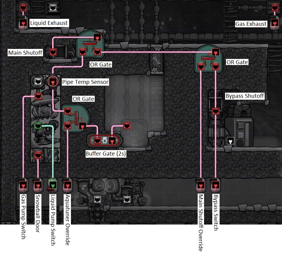 Though complex looking, the machine’s operation is mostly automatic and the various switches and controls intend to anticipate issues during the process of making liquid Oxygen/Hydrogen. The machine is not fully automatic and does require some supervision during operation.
Normal Use Controls:
Though complex looking, the machine’s operation is mostly automatic and the various switches and controls intend to anticipate issues during the process of making liquid Oxygen/Hydrogen. The machine is not fully automatic and does require some supervision during operation.
Normal Use Controls:- Pipe Temperature Sensor: set to -190C to make liquid Oxygen, and -255C for liquid Hydrogen.
- Liquid Pump Switch: turn on to pump the available liquid Oxygen/Hydrogen to the rocket.
- Gas Pump Switch:vacuum all gases inside the chamber to switch from making oxygen to hydrogen (or vice versa).
Occasional Use Controls:
- Bypass Switch: sends coolant thru pipes that bypass the Aquatuner and flow directly to the cooling chamber; used occasionally to nudge the Temp Sensor if “freezes”. Also use in the rare circumstance when the coolant gets “too cold”.
- Liquid Exhaust: empty any leftover liquid left in the fueling pipes.
- Gas Exhaust: empty any leftover gas left in the gas intake ducts.
Rare Use Controls:
- Main Shutoff Override: manually turn-on the Main Shutoff.
- Aquatuner Override: manually tun-on the Aquatuner.
- Snowball Door: use in extreme cases to quickly empty any solids from the chamber.
HEAT MANAGEMENT
As I mentioned earlier, a key component of any Liquid Oxygen/Hydrogen machine is heat management. At full swing, cooling Super-Coolant that circulates thru it at a rate of 10kg/s (normal pipe flow), the Aquatuner will produce around 1,200kDTU/s. This is a massive amount of heat that will easily overwhelm any system with poor Heat Management.
The focus of this design, then, is to quickly “remove” this massive heat generated inside the Aquatuner and deposit it “elsewhere”. This heat transfer scheme must be very dependable and work as intended continuously without any trouble, otherwise our Aquatuner will quickly overheat.
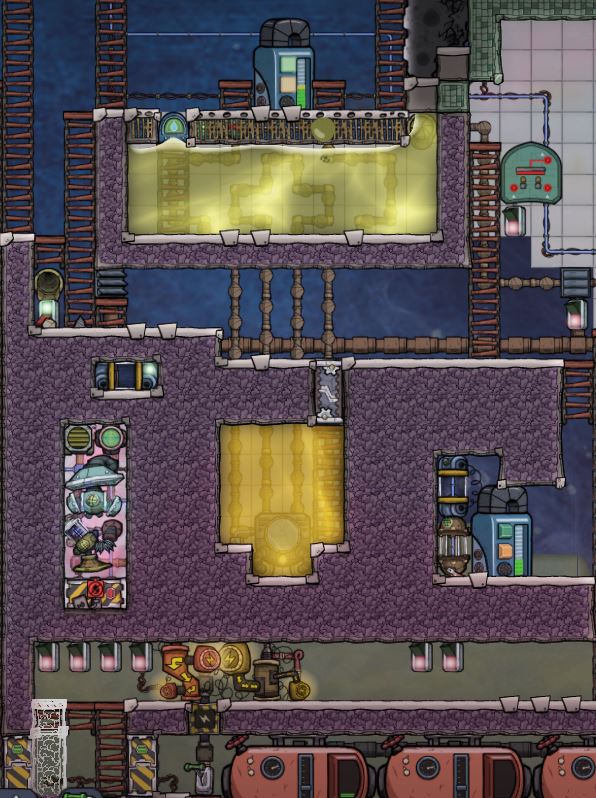
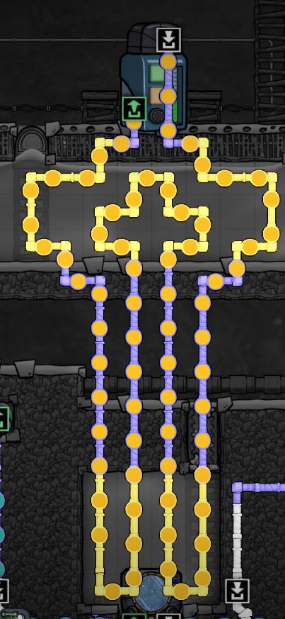 The heat transfer scheme of this machine is shown on the left: the Aquatuner is submerged in petroleum (which has a high heat transfer and boiling point); the heat generated here is absorbed by a “double flow” of petroleum going thru the radiant pipes, and then carried away from the Aquatuner chamber and transferred to the upper pool filled with polluted water.
As it turns out, heating Polluted Water from 45C to its boiling point of 119C requires a lot of heat; so, in effect we are boiling the polluted water not because we are interested in obtaining steam, but because we want the water to absorb the massive heat generated by the Aquatuner.
If you do some calculations, the heat generated by the Aquatuner to cool 1T of Super-Coolant from 70C to -255C, plus the amount to cool down 2.6T of Oxygen from 70C to -190C, plus the amount to cool 2.6T of Hydrogen from 70C to -255C – i.e., the total heat generated by the Aquatuner to send our first mission to the Temporal Tear, will boil about 22T of Polluted water from 45C to 119C.
My design uses a pool filled with 30T of Polluted Water, giving us a generous safety margin of 8T. So, likely, after your first mission, you will still have water there, although very hot. Eventually, the water will boil over and the idea is that the steam escapes to the vacuum of the space, so that the pool can be filled again.Here I am showing the pool of 30T of Polluted Water and its starting temperature of roughly 47C. Notice that the starting temperature of this mass of water is key for the system to function, and you will not get the same performance if, for example, you fill the pool with water starting at 90C.
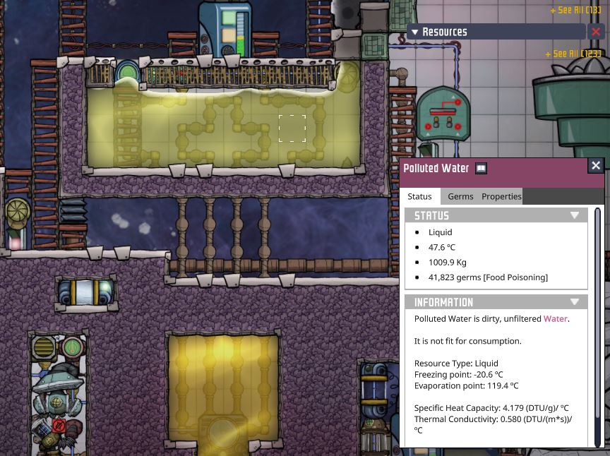 Subsequent missions to deep space would only generate heat to boil 9T of water per trip (because we now start with cold super-coolant), so this design is good to reach the Temporal Tear and then send a few more missions to that neighborhood. If 9T of polluted water seem a high cost per mission, mind that a mission back and forth lasts 40-50 cycles, so in the Great Scheme of Things, 9T (or even 30T) are very affordable, provided that you have decent water management.
LIQUID O2/H2 PRODUCTION
 The Liquid Valve is a necessity when the machine is started for the first time and you cool the 1T of super-coolant all the way from 70C to -190C: this step generates a lot of heat continuously for several cycles, and this design is limited by the specific heat of our heat transfer fluid (Petroleum), so we risk overheating for this initial stage.
Hence, and just for the first time we start the machine, we set the Liquid Vale flow to 60% (6kg/s) and leave it like that until all our super-coolant has cooled to -190C. After that milestone temperature is reached, we can set the Liquid Valve back to 100% (10kg/s) and our system will have capacity to absorb heat of subsequent use, which is more intermittent in nature.
After we reach our first temperature milestone (-190C) we can start making Liquid Oxygen.
When super-coolant at -190C reaches the Pipe Temperature Sensor, the sensor turns off the Main Shutoff Valve and the Aquatuner (the latter after 2 seconds delay), so the cold super-coolant stays “trapped” inside the cooling chamber.
Oxygen gas enters the chamber and warms up the super-coolant; when the coolant warms up above -190C, the Temp Sensor triggers and allows "new" cold coolant to enter the chamber. This cycle will repeat a few times until the Oxygen gas inside the chamber reaches -190C and turns into liquid.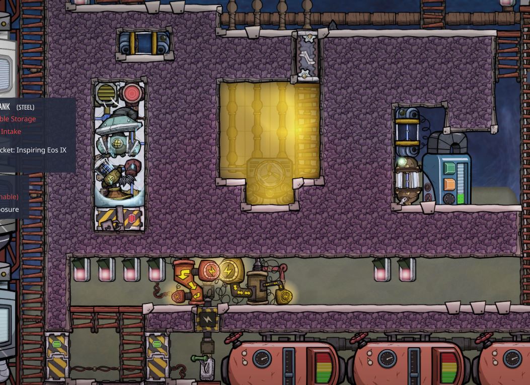 We then pump immediately the liquid Oxygen to the liquid Oxygen tank as shown below. Notice that the liquid Oxygen tank is the only tank plumbed to the output of the Liquid Pump, so the liquid flows naturally to it and not elsewhere.
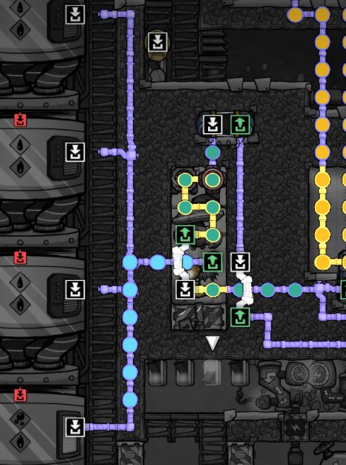 So, yes, an inconvenient limitation of this design is that you have to manually plumb the tank you are currently fueling and make sure all the other ones are not plumbed. This limitation is because our Insulated Piping here, even when it’s made of ceramic and has the protection of the Insulated Wall, is still susceptible to damage.
For this design in particular, damage to the pipes only occurred when fueling the top liquid Hydrogen tank; but that damage was very manageable and I had extra ceramic and dupe access available, anticipating this issue. This limitation/inconvenience is a bargain we make to avoid the trouble of making tons of Insulation.
If you got to this point, you get the idea of this machine and know what’s next to make liquid Hydrogen. We vacuum the chamber of any lingering oxygen, fill it up to Hydrogen, and setup the Pipe Temperature Sensor to -255C.
Hydrogen is a bit more unstable than oxygen, because it becomes liquid at -252.15C, and solidifies at -259.15C, so you have a much smaller temperature buffer to work with. You will see on occasion some sublimation happen that quickly turns back into liquid.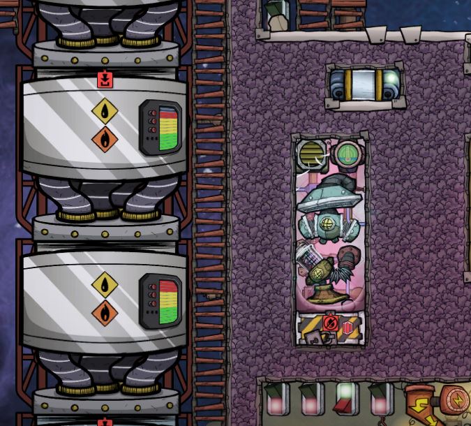 Under some circumstances, sublimation can become a problem, with gas only sublimating into solid, not changing back to liquid, no liquid being produced at all, and no way to reverse this cycle (you would then have to use the bypass flow to "warm up" the solid hydrogen, or use the Snowball door as a last resort).
To avoid this bad sublimation, I recommend pumping out the liquid Hydrogen immediately, and keeping the inflow of Hydrogen as continuous and full as possible, and the best way to do this, is to do your homework and have all your 2.6T of Hydrogen gas made and ready to be pumped before you start this process.
At the end of this process, with all tanks fully fueled, my pool of water ended up at 100.4C (starting from 47C), so maybe I can fuel another mission before the water boils over and evaporates to outer space.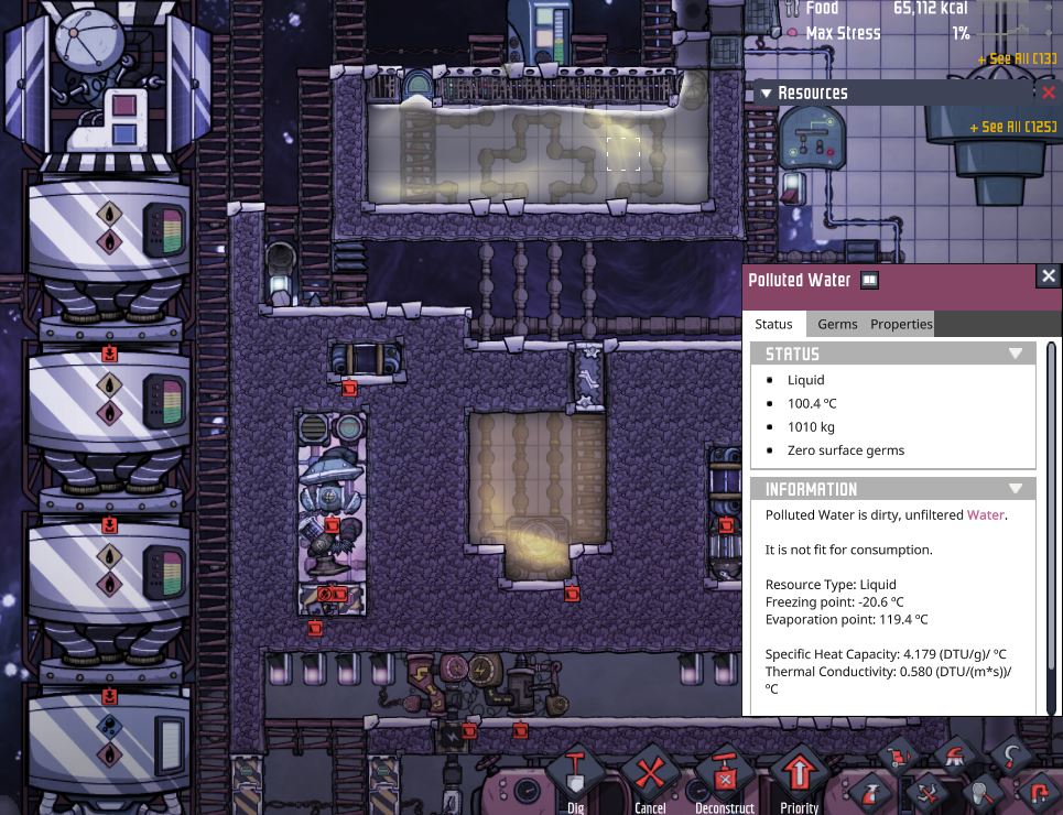
LAUNCH AND CONCLUSSION
- ONI - Surviving the Early Game★ 5 (2.4k)83k views6.3k ♥54 minUpdated 6 Aug, 2019
- Useful Construction Patterns★ 5 (1.8k)74k views5.2k ♥66 minUpdated 29 Aug, 2020
- 10* things I wish I knew sooner...★ 5 (754)58k views1k ♥4 minUpdated 6 Oct, 2017
- ONI - Surviving the Mid-Game★ 5 (1.3k)44k views3.8k ♥150 minUpdated 6 Sep, 2019
- Not Quite Beginner's Guide★ 5 (361)32k views1.1k ♥91 minUpdated Mar 26, 2023
- Руководство для начинающих. (ОСНОВЫ)★ 5 (629)32k views1.2k ♥21 minRussianUpdated 20 Apr, 2019





- Upgrading to PremiumTeam Fortress 2★ 5 (20k)1441k views11k ♥6 minUpdated May 11, 2022
- No More Room in Hell Official ManualNo More Room in Hell★ 5 (2.8k)569k views2.1k ♥29 minUpdated Apr 22, 2019
- NMRiH Community Hosting GuidesNo More Room in Hell★ 5 (526)351k views653 ♥1 minUpdated Aug 10, 2022
- ULTIMATE GUIDE FOR GAME DEV TYCOONGame Dev Tycoon★ 5 (5.8k)326k views10k ♥4 minUpdated 23 Jan, 2014
- How to 'Git Gud' Soon™MORDHAU★ 5 (2k)318k views3k ♥68 minUpdated Nov 16, 2024
- Лучшие кооперативные игры SteamPAYDAY 2★ 5 (1.5k)315k views2.1k ♥56 minRussianUpdated Apr 27, 2025






This guide was created by its original author on the Steam Community. Are you the author and want it removed? Request removal.